EP1037052B1 - Rotational pulse generating circuit for commutator DC motors - Google Patents
Rotational pulse generating circuit for commutator DC motors Download PDFInfo
- Publication number
- EP1037052B1 EP1037052B1 EP00105586A EP00105586A EP1037052B1 EP 1037052 B1 EP1037052 B1 EP 1037052B1 EP 00105586 A EP00105586 A EP 00105586A EP 00105586 A EP00105586 A EP 00105586A EP 1037052 B1 EP1037052 B1 EP 1037052B1
- Authority
- EP
- European Patent Office
- Prior art keywords
- motor
- signal
- commutator
- rotational
- circuit
- Prior art date
- Legal status (The legal status is an assumption and is not a legal conclusion. Google has not performed a legal analysis and makes no representation as to the accuracy of the status listed.)
- Expired - Lifetime
Links
- 238000007493 shaping process Methods 0.000 claims description 11
- 230000010355 oscillation Effects 0.000 claims description 10
- 230000000977 initiatory effect Effects 0.000 claims description 7
- 239000003990 capacitor Substances 0.000 description 14
- 238000010586 diagram Methods 0.000 description 4
- 230000008859 change Effects 0.000 description 3
- 230000007423 decrease Effects 0.000 description 3
- 238000007689 inspection Methods 0.000 description 3
- 230000015572 biosynthetic process Effects 0.000 description 2
- 238000006243 chemical reaction Methods 0.000 description 2
- 238000010168 coupling process Methods 0.000 description 2
- 238000005859 coupling reaction Methods 0.000 description 2
- 238000013016 damping Methods 0.000 description 2
- 230000003247 decreasing effect Effects 0.000 description 2
- 230000001419 dependent effect Effects 0.000 description 2
- 230000003321 amplification Effects 0.000 description 1
- 230000008878 coupling Effects 0.000 description 1
- 230000001934 delay Effects 0.000 description 1
- 238000006073 displacement reaction Methods 0.000 description 1
- 230000000694 effects Effects 0.000 description 1
- 230000004048 modification Effects 0.000 description 1
- 238000012986 modification Methods 0.000 description 1
- 238000003199 nucleic acid amplification method Methods 0.000 description 1
- 230000010363 phase shift Effects 0.000 description 1
- 239000000843 powder Substances 0.000 description 1
- 230000002265 prevention Effects 0.000 description 1
- 230000009467 reduction Effects 0.000 description 1
- 230000004044 response Effects 0.000 description 1
- 239000004065 semiconductor Substances 0.000 description 1
- 230000000087 stabilizing effect Effects 0.000 description 1
Images




Classifications
-
- G—PHYSICS
- G01—MEASURING; TESTING
- G01P—MEASURING LINEAR OR ANGULAR SPEED, ACCELERATION, DECELERATION, OR SHOCK; INDICATING PRESENCE, ABSENCE, OR DIRECTION, OF MOVEMENT
- G01P3/00—Measuring linear or angular speed; Measuring differences of linear or angular speeds
- G01P3/42—Devices characterised by the use of electric or magnetic means
- G01P3/44—Devices characterised by the use of electric or magnetic means for measuring angular speed
- G01P3/48—Devices characterised by the use of electric or magnetic means for measuring angular speed by measuring frequency of generated current or voltage
-
- H—ELECTRICITY
- H02—GENERATION; CONVERSION OR DISTRIBUTION OF ELECTRIC POWER
- H02P—CONTROL OR REGULATION OF ELECTRIC MOTORS, ELECTRIC GENERATORS OR DYNAMO-ELECTRIC CONVERTERS; CONTROLLING TRANSFORMERS, REACTORS OR CHOKE COILS
- H02P7/00—Arrangements for regulating or controlling the speed or torque of electric DC motors
- H02P7/0094—Arrangements for regulating or controlling the speed or torque of electric DC motors wherein the position is detected using the ripple of the current caused by the commutator
Definitions
- the present invention is directed to a rotational pulse generating circuit of a commutator DC motor according to the preamble of claim 1.
- EP 997 341 discloses an electric circuit for detecting a rotational condition of a commutator or brush-equipped DC motor depending on a ripple pulse frequency which is indicative of a rotational number of the commutator DC motor.
- An output of such a circuit is in the form of a pulse train which is indicative of the rotational number of the commutator DC motor.
- This circuit is used to control a position of a vehicular movable member such as a seat or window pane which is driven by the commutator DC motor in such a manner that the output pulse train signal is fed to a micro-processor for positioning the vehicular movable member.
- document US-A-924 166 discloses a circuit for shaping ripple in the armature current of a DC-motor.
- the present invention provides a rotational pulse generating circuit for a commutator DC motor as claimed in the appended claims.
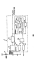
- FIG. 1 there is illustrated a schematic diagram of a rotational pulse generating circuit 3 which generates ripple pulse train indicative of the number of rotation of a commutator DC motor 1.
- the circuit 3 includes a switched capacitance filter (SCF) 3a which will be hereinafter simply referred to as a filter, a ripple pulse shaping circuit 3b, and a phase locked loop circuit 3c, a frequency demultiplier circuit 3d, an amplifier circuit 3e, an amplifier circuit or frequency divider circuit 3f, and an adding circuit 3g.
- SCF switched capacitance filter
- the switched capacitance filter 3a is so designed as to change its filter cutoff frequency fc in response to a change of filter constant upon receipt of an external signal, or clock signal.
- the ripple pulse shaping circuit 3b generates the ripple pulse train on the basis of an output of the switched capacitance filter 3a.
- the circuits 3c, 3d, 3e, 3f, and 3g constitute a clock signal generating circuit which varies the cutoff frequency fc of the switched capacitance filter 3a on the basis of the ripple pulse train issued from the ripple pulse shaping circuit 3b and motor rotational condition signal which is made up of a motor rotational signal and a motor driving voltage Vb.
- the phase locked loop circuit 3c is made up of a phase comparison circuit 3ca, a low pass filter 3cb, and an oscillation circuit 3cc.
- the phase comparison circuit 3ca compares phases of signals inputted therein and issues an output signal depending on the resultant comparison.
- the low pass filter (LPF) 3cb smoothes the signal outputted from the phase comparison circuit 3ca.
- the oscillation circuit (VCO) 3cc oscillates a clock signal whose frequency is 100f which depends on a differential signal between the motor rotational condition signal and the output signal of the low pass filter 3cb.
- the frequency divider circuit 3d divides the oscillation frequency of the clock signal issued from the oscillation circuit 3cc to f.
- the amplifier circuit 3e amplifies a motor rotational signal issued from the commutator DC motor 11 which is in the form of a voltage signal depending on a motor driving voltage, while the amplifier circuit 3f amplifies the motor driving voltage Vb.
- Amplified signals issued from the respective amplifier circuits 3e and 3f are fed to the adding circuit 3g to be added therein and the resultant signal is fed, as a motor rotational condition signal, to the oscillation circuit 3cc.
- the switched capacitance can be regarded as an equivalency of a resistor R.
- the cutoff frequency fc of a CR-filter shown in FIG.2(b) which is an application of such a switched capacitance circuit becomes variable depending on frequency for alternately turning on-and-off of switches. In the case of the switched capacitance filter, instead of frequency, clock input is used. Such a cutoff frequency fc can be expressed as a depicted formula in FIG.2(b).
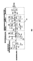
- the ripple pulse shaping circuit 3b includes a high frequency active filter FL2, a first differentiating circuit DC1, a second differentiating circuit DC2, an amplifier AP1, and a voltage comparator CM.
- the high frequency active filter FL2 a series of resistors R3 and R4 are coupled to a non-inverting terminal of an operational amplifier OP1 which is also grounded to the earth by way of a capacitor C2.
- An inverting terminal of the operational amplifier OP1 is connected via a capacitor C3 to a connecting point at which the resistors R3 and R4 meet for feedback control.
- the high frequency active filter FL2 serves for eliminating a high frequency component of the motor rotational signal.
- noise component above the maximum rotational speed say , 6000 rpm
- LPF low pass filter
- the first differentiating circuit DC1 is connected to an output terminal (b) of the low pass filter LPF, or high frequency active filter FL2 for differentiating the signal issued or outputted therefrom which brings damping, or decaying components of the signal.
- a series connection of a resistor R7 and a coupling capacitor C5 is connected to an inverting terminal of an operational amplifier OP2.
- a voltage divided by resistors R5 and R6 connected in series is applied to a non-inverting terminal of the operational amplifier OP2 and a connecting point at which the resistors R5 and R6 meet is coupled with a bypass capacitor C4.
- a parallel connection of a resistor R8 and a capacitor C6 is connected between the non-inverting input terminal and an output terminal (c) of the operational amplifier OP2.
- the amplifier AP1 is so designed as to amplify a signal issued from the output terminal (c) of the operational amplifier OP2 of the first differentiating circuit DC1.
- the amplifier AP1 includes an operational amplifier OP3 whose non-inverting input terminal is connected to the output terminal ( c) of the operational amplifier OP2 via a series of resistors R9 and R10.
- the non-inverting input terminal of the operational amplifier OP3 is also grounded by way of a capacitor C9.
- a capacitor C7 interposed between an inverting terminal of the operational amplifier OP3 and a point at which the resistors R9 and R10.
- the inverting terminal of the operational amplifier OP3 is grounded by way of a resistor R11.
- a capacitor C8 and a resistor R12 which are arranged in parallel are connected between the inverting input terminal and an output terminal (d) of the operational amplifier OP3.
- the second differentiating circuit DC2 is connected to the output terminal (d) of the operational amplifier OP3 of the amplifier AP1 low pass filter LPF and differentiates a signal outputted therefrom for establishing a phase shift of 90 degrees.
- the second differentiating circuit DC2 includes an operational amplifier OP4 whose non-inverting input terminal is connected to the output terminal (d) of the operational amplifier OP3 of the amplifier AP1 via a resistor R13.
- the non-inverting input terminal of the operational amplifier OP4 is grounded by way of a capacitor C11.
- a resistor R13 and a capacitor C10 which are arranged in series.
- a resistor R15 and a capacitor C12 which are arranged in parallel are connected between the inverting input terminal and an output terminal of the operational amplifier OP4.
- the comparator CM compares output signals from the respective output terminal (e) of the second differentiating circuit DC2 and output terminal (d) of the amplifier circuit AP1.
- the comparator CM includes an operational amplifier OP5 whose inverting input terminal is connected via a resistor R17 to the output terminal (d) of the operational amplifier OP3 of the amplifier circuit AP1.
- a non-inverting input terminal of the operational amplifier OP5 is connected via a resistor R7 to the output terminal (e) of the operational amplifier OP4 of the second differentiating circuit DC2.
- a resistor R18 is connected between the non-inverting input terminal and the output terminal (f) of the operational amplifier OP5.
- a rectangular pulse train signal or a ripple pulse train signal is set to be outputted which is corresponded to the ripple frequency. It is to be noted that this 'ripple pulse train' is based on motor ripple and therefore its wave-shape is in the form of 'ripple'.
- the signal at each of the output terminals (a), (b), (c), (d), (e), and (f) in the pulse wave-form shaping circuit 3b takes a wave shape as illustrated in FIG.4.
- the current flowing through the commutator DC motor 11 is converted into a voltage signal, or motor rotational signal which is in proportion thereto in magnitude.
- This voltage signal is superposed with ripple together with noise and has a wave shape indicated with 'a' in FIG.4.
- the ripple is inevitable, as is well known, when the commutator DC motor is being driven or turned on.
- the noise superposed on the voltage signal is deleted or eliminated from the voltage signal.
- another noise superposed on the clock input whose clock frequency is fCLK which is inputted to the switched capacitance filter 3a appears on the voltage signal when outputted from the switched capacitance filter 3a.
- the voltage signal after passing though the high frequency active filter FL2, comes to have the wave shape as indicated with 'b' in FIG. 4 which is smooth, noise-deleted. Passing such a voltage signal having the wave-shape 'b' through the first differentiating circuit DC1 makes the voltage signal differentiated, thereby to damp or decay its DC component.
- the resultant voltage signal becomes to have wave-shape 'c' in which only a ripple component is involved. Furthermore, if the voltage signal passes through the amplifier AP1, the amplitude of the voltage signal is amplified to have the wave shape 'd'. Thereafter, passing such a voltage signal through the second differentiating circuit DC2 brings that the voltage signal becomes to have the wave shape 'e' which delays in a phase of 90 degrees with respect to the wave shape 'd'. Then, comparing the voltage signal having the wave shape 'd' which is outputted from the amplifier AP1 and the voltage signal having the wave shape 'e' which is outputted from the second differentiating circuit DC2, the compactor CM issues the ripple pulse train signal having the wave-shape 'f'.
- a clock signal is generated which is used as a clock input for the switched capacitance filter 3a by a frequency conversion such that the frequency of the ripple signal is multiplied by an integer.
- a feedback of the ripple pulse signal is made in synchronization with the motor rotational condition signal so that the frequency f of the ripple pulse is brought into coincidence with the cutoff frequency fc of the switched capacitance filter 3a.
- the output of the phase lock loop circuit 3c having a frequency of 100fp is divided by 100 at the frequency demultiplier 3d and the frequency demultiplier 3d feeds the resultant frequency of fp to one of input terminals of the phase comparison circuit 3ca, while the other input terminal of the phase comparison circuit 3ca is fed with the ripple pulse signal.
- a phase control of the output signal of the frequency demultiplier 3d is made to oscillate a frequency which is in coincidence with the frequency fp of ripple pulse inputted to the phase locked circuit (PLL) 3c.
- PLL phase locked circuit
- outputting the clock signal is made to be stabilized in a steady area.
- the oscillation circuit 3cc is fed with the motor rotation condition signal which is made up of the motor rotational signal and the motor driving voltage signal, thereby not making the output of ripple pulse unstable.
- the motor rotational condition signals serves for producing the ripple pulse train without generating any error pulse.
- the rotational number of the commutator DC motor 11 varies with or depends on the driving voltage Vb.
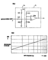
- the rotational number of the commutator DC motor 11 is determined with the usage of a map, or graph shown in FIG.5 which reveals a relationship between the motor rotational number and a motor current.
- the motor current is obtained by dividing the motor driving voltage Vb by a shunt resistor R. This graph shows the relationship in case where the motor driving voltage Vb varies from 9 though 16 volts and indicates that the line connecting the motor current and the motor rotational number makes parallel displacements toward a higher side.
- the 3cc produces a clock pulse having a frequency, or the cutoff frequency fc which is an integral multiplier of the frequency fx. That is to say, when the commutator DC motor 11 is turned on, the 3cc issues the clock signal folk on the basis of the motor rotational signal and the motor driving voltage, which enable the cutoff frequency to vary, thereby producing a ripple pulse which reflects the motor rotational condition.
- the circuit 3c makes the phase control of the clock signal by means of feedback control in such a manner of coincidence between the ripple pulse having the frequency f and the signal outputted from the demultiplier circuit 3d in phase. This ensures that the switched capacitance filter 3a is inputted with the clock signal of stable oscillation.
- the cutoff frequency fc of the switched capacitance filter 3a even at an initial phase of the commutator DC motor 11, becomes variable in linear mode and the ripple pulses are produced depending on the variable cutoff frequency.
- the signal takes its wave forms 'a'. 'g', 'h', and 'f' at the respective output terminals (a), (g), (h), and (f).
- the signal takes its wave forms 'a', 'g', 'h', and 'f' at the respective output terminals (a), (g), (h), and (f).
- the wave form 'h' in FIG.6(a) reveals that the cutoff frequency fc can be made to be variable depending on the motor rotation condition while the commutator DC motor 11 is in its initiation area which starts with the initiation of the commutator DC motor 11 and terminates in when the motor current becomes stable, particularly in an earlier stage of the initiation area which starts with the initiation of the commutator DC motor 11 and terminates in producing the ripple pulse.
- controlling optimally the cutoff frequency enables the prevention of occurrence of error pulses.
- FIG.7 there is illustrated a modified structure of the circuit 3 shown in FIG.1 which is constructed in such a manner that an in-series connection of a high pass filter 3h and an amplifier 3i is interposed between the commutator DC motor 11 and the switched capacitance filter 3a.
- This circuit 3 shown in FIG.7 is an improved version of the circuit 3 shown in FIG.1.
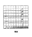
- the commutator DC motor 11 has not been used frequently, its motor current which is a parameter for producing the ripple pulse by way of the motor rotational signal, as shown in FIG.11(a), the ripple components of the signals at the output terminals (a), (d), (e), and (f) appear surely.
- the reason is that in the commutator DC motor 11 which is not overworked an uneven friction wear of the brush relative to the communicator and/or wear powder entered between the brush and the communicator are seldom found.
- the high pass filter 3h is made up of a capacitor C20, a resistor R21, and a resistor R22, while the amplifier 3 i is constituted by an operational amplifier OP0, a resistor R23, and a resistor R24.
- the amplifying rate is restricted so as to be constant, while below the amplification factor rate is decreased as the ripple frequency decreases.
- the motor rotational signal issued from the commutator DC motor 11 is fed, after condenser-coupling at a condenser C20, to a non-inverting terminal of the operational amplifier OP0 together with a voltage which is obtained by dividing a voltage Vcc of, for example, 5 volts by resistors R23 and R24.
- a feedback of an output of the operational amplifier OP0 is made to the non-inverted terminal of the operational amplifier OP0 by way of the resistor R23, with the result that the resistors R23 and R24 constitute an inverting differential amplifier 3i.
- the high pass filter 3h can decay the frequency component less than the ripple pulse frequency, resulting in that despite of decrease of ripple component with age such frequency component is made not to affect the formation of the pulse signal ('c' in FIG.6).
- the commutator DC motor 11 is used which is an aged one, pulse formation is ensured to be formed in any frequency area.
- FIG.10 a wave-shape of the signal at each point or terminal in the second embodiment is depicted in FIG.10.
- adding the simple circuit merely enables to issue ripple pulses without generating error pulse.
- the set of the high pass filter 3h and the amplifier 3I are provided at a front stage of the switched capacitance filter 3a in the second embodiment, such an arrangement is not restrictive nature and therefore the effects resulting from such an arrangement remains unchanged even if the set of the high pass filter 3h and the amplifier 3i is provided , or placed at a rear stage of the switched capacitance filter 3a.
- the cutoff frequency of the filter means 3a becomes variable by being fed with the clock signal which is generated based on the ripple pulse and the rotational condition signal of the commutator DC motor 11, which allows the circuit 3 to ensuring correct ripple pulse generation depending on the change of rotational condition of the commutator DC motor 11 which is affected by motor load, rotation, driving voltage, environment and so on.
- the ripple pulse generation remains correct by changing the cutoff filter of the filter means 3a based on the resultant motor rotation.
- the cutoff frequency of the filter means 3a is determined at the initiation of the commutator DC motor 11 by the motor rotational condition signal which is made up of the motor rotational signal and the motor driving voltage signal, at this time, even prior to the ripple pulse generation by the pulse forming means 3b, the ripple pulse generation becomes possible by the motor rotational condition signal made up of motor rotational signal and the motor driving voltage signal, which makes the ripple pulse generated in correct or steady dependent of the motor rotational condition even immediately when the commutator DC motor 11 is initiated.
- the clock generation means includes the oscillation circuit 3cc which operates to issue the clock signal so as to be in coincidence with the ripple pulse in frequency phase by feedback control, thereby enabling steady generation of the ripple pulse.
- the provision of the amplitude correction means which passes only the high frequency component between the motor and the filter means brings the ripple pulse generation in correct in any motor rotational area even if the motor is changed with passing of time.
Landscapes
- Physics & Mathematics (AREA)
- General Physics & Mathematics (AREA)
- Engineering & Computer Science (AREA)
- Power Engineering (AREA)
- Control Of Direct Current Motors (AREA)
- Control Of Motors That Do Not Use Commutators (AREA)
- Stabilization Of Oscillater, Synchronisation, Frequency Synthesizers (AREA)
Description
Claims (4)
- A rotational pulse generating circuit for a commutator DC motor comprising:characterized byfilter means (3a) for eliminating noise from a motor rotational signal which is proportional to the DC motor (11) current;pulse shaping means (3b) for generating a ripple pulse train signal (f) as a rotational pulse indicative of a rotational number of the commutator DC motor (11) by wave-shaping an output of the filter means;a circuit (3e, 3f, 3g) for generating a motor rotational condition signal on the basis of the motor rotational signal and a motor driving voltage; andclock generating means (3c) for generating a clock signal (fCLK) and for feeding the clock signal (fCLK) to the filter means (3a) for making the cutoff frequency of the filter means variable;
the clock generating means (3c) generating the clock signal (fCLK) on the basis of the ripple pulse train signal (f) and the motor rotational condition signal. - A rotational pulse generating circuit for a commutator DC motor as set forth in claim 1, characterized in that the cutoff frequency at an initiation of the commutator DC motor (11) is determined by the motor rotational condition signal.
- A rotational pulse generating circuit for a commutator DC motor as set forth in claim 1, characterized in that the clock generating means (3c) includes an oscillation circuit (3cc) whose output signal is brought into coincidence with the ripple pulse train signal (f) in phase.
- A rotational pulse generating circuit for a commutator DC motor as set forth in claim 1, characterized by amplitude correction means (3h, 3i) interposed between the commutator DC motor (11) and the filter means (3a), wherein the amplitude correcting means (3h, 3i) passes therethrough only a higher frequency component of the signal representative of the motor current.
Applications Claiming Priority (4)
| Application Number | Priority Date | Filing Date | Title |
|---|---|---|---|
| JP7369499 | 1999-03-18 | ||
| JP7369499 | 1999-03-18 | ||
| JP2000017438 | 2000-01-26 | ||
| JP2000017438A JP4395956B2 (en) | 1999-03-18 | 2000-01-26 | Motor rotation pulse generation circuit for DC motor |
Publications (2)
| Publication Number | Publication Date |
|---|---|
| EP1037052A1 EP1037052A1 (en) | 2000-09-20 |
| EP1037052B1 true EP1037052B1 (en) | 2003-10-08 |
Family
ID=26414831
Family Applications (1)
| Application Number | Title | Priority Date | Filing Date |
|---|---|---|---|
| EP00105586A Expired - Lifetime EP1037052B1 (en) | 1999-03-18 | 2000-03-16 | Rotational pulse generating circuit for commutator DC motors |
Country Status (4)
| Country | Link |
|---|---|
| US (1) | US6326757B1 (en) |
| EP (1) | EP1037052B1 (en) |
| JP (1) | JP4395956B2 (en) |
| DE (1) | DE60005727T2 (en) |
Cited By (3)
| Publication number | Priority date | Publication date | Assignee | Title |
|---|---|---|---|---|
| DE102008026091A1 (en) | 2008-05-30 | 2009-12-17 | Brose Fahrzeugteile Gmbh & Co. Kommanditgesellschaft, Hallstadt | Speed proportional rectangular signal producing method for permanently excited direct current motor of power window drive for motor vehicle, involves adjusting resonant frequency of controllable frequency filter |
| DE102009014264A1 (en) | 2008-09-12 | 2010-04-15 | Brose Fahrzeugteile Gmbh & Co. Kommanditgesellschaft, Hallstadt | Method and device for processing a current ripple having motor signal of a DC motor |
| US8562304B2 (en) | 2008-04-15 | 2013-10-22 | Continental Teves Ag & Co. Ohg | Electrical motor activation method having load torque adaptation |
Families Citing this family (25)
| Publication number | Priority date | Publication date | Assignee | Title |
|---|---|---|---|---|
| JP4433547B2 (en) * | 2000-02-29 | 2010-03-17 | アイシン精機株式会社 | Motor rotation pulse generator |
| DE10028038A1 (en) * | 2000-06-06 | 2001-12-13 | Kostal Leopold Gmbh & Co Kg | Position determining method for DC-motor-driven element, involves moving element to block position on system side and afterwards to mechanically defined block position, and normalizing block position on system side |
| BR0106746A (en) * | 2000-06-06 | 2002-04-02 | Kostal Leopold Gmbh & Co Kg | Process and device for determining the turning position of the drive shaft of a DC motor |
| DE10028041A1 (en) * | 2000-06-06 | 2001-12-13 | Kostal Leopold Gmbh & Co Kg | Determining the position of an element, e.g. sun roof of vehicle, actuated by the drive shaft of DC motor, involves evaluating current ripple contained in armature current signal when moving element from one block position to another |
| JP4691820B2 (en) * | 2001-04-25 | 2011-06-01 | アイシン精機株式会社 | Motor control device |
| JP2003009585A (en) * | 2001-06-20 | 2003-01-10 | Aisin Seiki Co Ltd | DC motor rotation status detector |
| US6759822B2 (en) * | 2001-12-20 | 2004-07-06 | Southern Illinois University | Methods and apparatus to improve the performance of universal electric motors |
| EP1556944A1 (en) * | 2002-10-29 | 2005-07-27 | Seiko Epson Corporation | Displacement control system for a vehicle axle |
| US20050192519A1 (en) * | 2004-02-27 | 2005-09-01 | John Crunick | Motor assemblies and massage assemblies using the same |
| JP4127251B2 (en) * | 2004-07-23 | 2008-07-30 | 株式会社デンソー | DC motor rotation information detector |
| FR2880741B1 (en) * | 2005-01-11 | 2007-04-27 | Somfy Sas | METHOD FOR DETERMINING THE POSITION AND / OR SPEED OF ROTATION OF THE SHAFT OF A DRIVE MOTOR OF A SHUTTER AND ACTUATOR FOR IMPLEMENTING SUCH A METHOD |
| US7180255B2 (en) * | 2005-01-26 | 2007-02-20 | Delphi Technologies, Inc. | Controlling the release of a brush motor which has applied a load |
| TWI274468B (en) * | 2005-05-04 | 2007-02-21 | Sunplus Technology Co Ltd | Brake system and method for a direct current brushed motor without a hall sensor |
| US20060261763A1 (en) * | 2005-05-23 | 2006-11-23 | Masco Corporation | Brushed motor position control based upon back current detection |
| JP4789554B2 (en) * | 2005-09-09 | 2011-10-12 | キヤノン株式会社 | Motor control device |
| US7352145B2 (en) * | 2005-10-04 | 2008-04-01 | Delphi Technologies, Inc. | Voltage-sensitive oscillator frequency for rotor position detection scheme |
| DE102005059862A1 (en) * | 2005-12-15 | 2007-06-28 | Hella Kgaa Hueck & Co. | Direct current motor for automotive engineering, has capacitor switched parallel to rotor winding in rotor, and inductor switched in series to condenser in stator, such that capacitor and inductor form resonance circuit of detection device |
| JP4763509B2 (en) * | 2006-05-23 | 2011-08-31 | アイシン精機株式会社 | Ripple detector |
| JP4939298B2 (en) * | 2007-05-09 | 2012-05-23 | アイシン精機株式会社 | DC motor ripple detection device, motor rotational position detection device, and ripple detection method |
| US20080298784A1 (en) * | 2007-06-04 | 2008-12-04 | Mark Allen Kastner | Method of Sensing Speed of Electric Motors and Generators |
| DE102008022621A1 (en) * | 2008-05-08 | 2009-11-12 | Hella Kgaa Hueck & Co. | Electric drive's position and/or angle of rotation and/or number of revolutions determining method for e.g. opening vehicle window, involves activating filters of filter bank, where electrical signal is filtered by activated filters |
| EP2180591B1 (en) * | 2008-10-21 | 2012-04-04 | Hella KGaA Hueck & Co. | Method for automatically determining the system dynamic and/or position of a permanently excited direct current motor |
| DE102016101905A1 (en) * | 2016-02-03 | 2017-08-03 | Brose Fahrzeugteile Gmbh & Co. Kommanditgesellschaft, Bamberg | Method for controlling an electric motor for an adjusting element of a motor vehicle |
| DE102019101897A1 (en) * | 2019-01-25 | 2020-07-30 | Minebea Mitsumi Inc. | Method and device for determining the speed of a rotating rotor |
| CN116722723A (en) * | 2023-05-24 | 2023-09-08 | 浙江优亿医疗器械股份有限公司 | A method and circuit for generating system clock based on reducing power supply ripple |
Citations (1)
| Publication number | Priority date | Publication date | Assignee | Title |
|---|---|---|---|---|
| EP0997341A1 (en) * | 1998-10-29 | 2000-05-03 | Aisin Seiki Kabushiki Kaisha | Control device for movable member |
Family Cites Families (17)
| Publication number | Priority date | Publication date | Assignee | Title |
|---|---|---|---|---|
| USRE29431E (en) * | 1974-09-06 | 1977-10-04 | Pertec Computer Corporation | Phase-locked loop for an electronic sectoring scheme for rotating magnetic memory |
| US3898690A (en) * | 1974-09-06 | 1975-08-05 | Pertec Corp | Phase-locked loop for an electronic sectoring scheme for rotating magnetic memory |
| US4494509A (en) * | 1982-10-22 | 1985-01-22 | Electromotive, Inc. | High resolution electronic ignition control system |
| FR2628906B1 (en) * | 1988-03-15 | 1990-08-24 | Jaeger | DEVICE FOR SHAPING AND EXPLOITING ARMATURE CURRENT Ripples GENERATED BY A DIRECT CURRENT MOTOR, PARTICULARLY FOR POSITIONING CONTROL |
| US5497326A (en) | 1994-08-03 | 1996-03-05 | The Cherry Corporation | Intelligent commutation pulse detection system to control electric D.C. motors used with automobile accessories |
| US5550880A (en) * | 1995-08-30 | 1996-08-27 | General Electric Company | Motor current signal processor using analog substraction of an estimated largest sine wave component |
| US5710714A (en) * | 1995-11-15 | 1998-01-20 | Applied Power Inc. | Electronic controller for an adaptively tuned vibration absorber |
| JPH1027348A (en) * | 1996-07-09 | 1998-01-27 | Pioneer Electron Corp | Recorded information reproducing device |
| JP3845849B2 (en) * | 1996-10-18 | 2006-11-15 | ソニー株式会社 | Recording apparatus, recording method, and recording medium |
| JPH10215175A (en) * | 1996-11-29 | 1998-08-11 | Sony Corp | PLL circuit and signal reproducing device |
| JPH10293926A (en) * | 1997-02-21 | 1998-11-04 | Pioneer Electron Corp | Recording clock signal generating device |
| US6172952B1 (en) * | 1997-06-11 | 2001-01-09 | Matsushita Electric Industrial Co., Ltd. | Optical disk device with abnormal jump detection |
| JP3607048B2 (en) * | 1997-06-26 | 2005-01-05 | 株式会社東芝 | Disc reproducing apparatus and data slicing circuit |
| JP3595144B2 (en) * | 1997-12-24 | 2004-12-02 | パイオニア株式会社 | Repeat control device and information reproducing device |
| US6208216B1 (en) * | 1998-09-28 | 2001-03-27 | Mikko J. Nasila | Phase-locked-loop pulse-width modulation system |
| JP4244412B2 (en) * | 1998-09-30 | 2009-03-25 | アイシン精機株式会社 | Motor rotation pulse generation circuit for DC motor and pinching detection device using the circuit |
| US6198354B1 (en) * | 1999-12-07 | 2001-03-06 | Hughes Electronics Corporation | System for limiting if variation in phase locked loops |
-
2000
- 2000-01-26 JP JP2000017438A patent/JP4395956B2/en not_active Expired - Fee Related
- 2000-03-16 EP EP00105586A patent/EP1037052B1/en not_active Expired - Lifetime
- 2000-03-16 DE DE60005727T patent/DE60005727T2/en not_active Expired - Lifetime
- 2000-03-17 US US09/528,153 patent/US6326757B1/en not_active Expired - Lifetime
Patent Citations (1)
| Publication number | Priority date | Publication date | Assignee | Title |
|---|---|---|---|---|
| EP0997341A1 (en) * | 1998-10-29 | 2000-05-03 | Aisin Seiki Kabushiki Kaisha | Control device for movable member |
Cited By (4)
| Publication number | Priority date | Publication date | Assignee | Title |
|---|---|---|---|---|
| US8562304B2 (en) | 2008-04-15 | 2013-10-22 | Continental Teves Ag & Co. Ohg | Electrical motor activation method having load torque adaptation |
| DE102008026091A1 (en) | 2008-05-30 | 2009-12-17 | Brose Fahrzeugteile Gmbh & Co. Kommanditgesellschaft, Hallstadt | Speed proportional rectangular signal producing method for permanently excited direct current motor of power window drive for motor vehicle, involves adjusting resonant frequency of controllable frequency filter |
| DE102008026091B4 (en) * | 2008-05-30 | 2011-11-24 | Brose Fahrzeugteile Gmbh & Co. Kommanditgesellschaft, Hallstadt | Method and device for generating a speed-proportional rectangular signal of a DC motor |
| DE102009014264A1 (en) | 2008-09-12 | 2010-04-15 | Brose Fahrzeugteile Gmbh & Co. Kommanditgesellschaft, Hallstadt | Method and device for processing a current ripple having motor signal of a DC motor |
Also Published As
| Publication number | Publication date |
|---|---|
| JP2000333485A (en) | 2000-11-30 |
| DE60005727T2 (en) | 2004-08-05 |
| EP1037052A1 (en) | 2000-09-20 |
| DE60005727D1 (en) | 2003-11-13 |
| US6326757B1 (en) | 2001-12-04 |
| JP4395956B2 (en) | 2010-01-13 |
Similar Documents
| Publication | Publication Date | Title |
|---|---|---|
| EP1037052A1 (en) | Rotational pulse generating circuit for commutator DC motors | |
| US6559616B2 (en) | Rotational pulse generating circuit for motors | |
| EP0363169B1 (en) | System for driving a brushless motor | |
| JP3327911B2 (en) | Interference cancellation circuit | |
| JP4655400B2 (en) | Motor rotation pulse generation circuit for DC motor | |
| US5122715A (en) | Drive device for a brushless motor | |
| US6412347B1 (en) | Angle speed sensor | |
| JPH01307312A (en) | Circuit for generating a series of pulses having predetermined and controlled impact coefficient | |
| JP3985362B2 (en) | Motor rotation pulse generation circuit for DC motor | |
| JP3326521B2 (en) | Capacitive detection device | |
| JP2703410B2 (en) | Voltage converter circuit | |
| CN1140359A (en) | A device for controlling the output level of an FM detection circuit with a phase-locked loop | |
| JPH05145784A (en) | Phase locked loop device | |
| JP2870466B2 (en) | Phase locked loop | |
| JP2001108444A (en) | Driver of vibrator | |
| JP3811884B2 (en) | Phase-locked oscillation circuit | |
| JPS58215B2 (en) | PLL circuit for timing extraction | |
| JP4421754B2 (en) | Phase comparison circuit, PLL circuit using the phase comparison circuit, and vibrator driving device using the PLL circuit | |
| JP2502577B2 (en) | Brushless motor drive | |
| JP2001085756A (en) | Vibration actuator drive | |
| JPH0235496B2 (en) | ||
| JPS5940711A (en) | Offset voltage generating circuit for operational amplifier | |
| JPH03239173A (en) | Motor servo system | |
| JPH01186192A (en) | Drive for brushless motor | |
| JPS6210448A (en) | Driving gear of solenoid valve for interval-combustion engine |
Legal Events
| Date | Code | Title | Description |
|---|---|---|---|
| PUAI | Public reference made under article 153(3) epc to a published international application that has entered the european phase |
Free format text: ORIGINAL CODE: 0009012 |
|
| AK | Designated contracting states |
Kind code of ref document: A1 Designated state(s): DE FR GB |
|
| AX | Request for extension of the european patent |
Free format text: AL;LT;LV;MK;RO;SI |
|
| 17P | Request for examination filed |
Effective date: 20000913 |
|
| AKX | Designation fees paid |
Free format text: DE FR GB |
|
| 17Q | First examination report despatched |
Effective date: 20010723 |
|
| GRAH | Despatch of communication of intention to grant a patent |
Free format text: ORIGINAL CODE: EPIDOS IGRA |
|
| GRAH | Despatch of communication of intention to grant a patent |
Free format text: ORIGINAL CODE: EPIDOS IGRA |
|
| GRAA | (expected) grant |
Free format text: ORIGINAL CODE: 0009210 |
|
| AK | Designated contracting states |
Kind code of ref document: B1 Designated state(s): DE FR GB |
|
| REG | Reference to a national code |
Ref country code: GB Ref legal event code: FG4D |
|
| REF | Corresponds to: |
Ref document number: 60005727 Country of ref document: DE Date of ref document: 20031113 Kind code of ref document: P |
|
| ET | Fr: translation filed | ||
| PLBE | No opposition filed within time limit |
Free format text: ORIGINAL CODE: 0009261 |
|
| STAA | Information on the status of an ep patent application or granted ep patent |
Free format text: STATUS: NO OPPOSITION FILED WITHIN TIME LIMIT |
|
| 26N | No opposition filed |
Effective date: 20040709 |
|
| REG | Reference to a national code |
Ref country code: GB Ref legal event code: 746 Effective date: 20121126 |
|
| REG | Reference to a national code |
Ref country code: DE Ref legal event code: R084 Ref document number: 60005727 Country of ref document: DE Effective date: 20121122 |
|
| PGFP | Annual fee paid to national office [announced via postgrant information from national office to epo] |
Ref country code: FR Payment date: 20140311 Year of fee payment: 15 |
|
| PGFP | Annual fee paid to national office [announced via postgrant information from national office to epo] |
Ref country code: GB Payment date: 20140312 Year of fee payment: 15 |
|
| PGFP | Annual fee paid to national office [announced via postgrant information from national office to epo] |
Ref country code: DE Payment date: 20140417 Year of fee payment: 15 |
|
| REG | Reference to a national code |
Ref country code: DE Ref legal event code: R119 Ref document number: 60005727 Country of ref document: DE |
|
| GBPC | Gb: european patent ceased through non-payment of renewal fee |
Effective date: 20150316 |
|
| REG | Reference to a national code |
Ref country code: FR Ref legal event code: ST Effective date: 20151130 |
|
| PG25 | Lapsed in a contracting state [announced via postgrant information from national office to epo] |
Ref country code: DE Free format text: LAPSE BECAUSE OF NON-PAYMENT OF DUE FEES Effective date: 20151001 Ref country code: GB Free format text: LAPSE BECAUSE OF NON-PAYMENT OF DUE FEES Effective date: 20150316 |
|
| PG25 | Lapsed in a contracting state [announced via postgrant information from national office to epo] |
Ref country code: FR Free format text: LAPSE BECAUSE OF NON-PAYMENT OF DUE FEES Effective date: 20150331 |