EP1037007A2 - Verschiebungsmessapparat - Google Patents
Verschiebungsmessapparat Download PDFInfo
- Publication number
- EP1037007A2 EP1037007A2 EP00104939A EP00104939A EP1037007A2 EP 1037007 A2 EP1037007 A2 EP 1037007A2 EP 00104939 A EP00104939 A EP 00104939A EP 00104939 A EP00104939 A EP 00104939A EP 1037007 A2 EP1037007 A2 EP 1037007A2
- Authority
- EP
- European Patent Office
- Prior art keywords
- wire
- pulley
- measuring apparatus
- displacement measuring
- pulleys
- Prior art date
- Legal status (The legal status is an assumption and is not a legal conclusion. Google has not performed a legal analysis and makes no representation as to the accuracy of the status listed.)
- Withdrawn
Links
- 238000006073 displacement reaction Methods 0.000 title claims abstract description 61
- 238000005259 measurement Methods 0.000 abstract description 17
- 238000010586 diagram Methods 0.000 description 7
- 230000005540 biological transmission Effects 0.000 description 5
- 230000006866 deterioration Effects 0.000 description 3
- 238000009434 installation Methods 0.000 description 3
- 239000011347 resin Substances 0.000 description 3
- 229920005989 resin Polymers 0.000 description 3
- 239000011248 coating agent Substances 0.000 description 1
- 238000000576 coating method Methods 0.000 description 1
- 238000010276 construction Methods 0.000 description 1
- 230000003247 decreasing effect Effects 0.000 description 1
- 230000002542 deteriorative effect Effects 0.000 description 1
- 230000000694 effects Effects 0.000 description 1
- 238000000034 method Methods 0.000 description 1
- 230000003287 optical effect Effects 0.000 description 1
- 238000007790 scraping Methods 0.000 description 1
- XLYOFNOQVPJJNP-UHFFFAOYSA-N water Substances O XLYOFNOQVPJJNP-UHFFFAOYSA-N 0.000 description 1
Images


Classifications
-
- G—PHYSICS
- G01—MEASURING; TESTING
- G01B—MEASURING LENGTH, THICKNESS OR SIMILAR LINEAR DIMENSIONS; MEASURING ANGLES; MEASURING AREAS; MEASURING IRREGULARITIES OF SURFACES OR CONTOURS
- G01B5/00—Measuring arrangements characterised by the use of mechanical techniques
- G01B5/0002—Arrangements for supporting, fixing or guiding the measuring instrument or the object to be measured
Definitions
- the present invention relates to an apparatus for measuring displacement by utilizing a wire.
- an apparatus for measuring a displacement along the stroke of a cylinder there is known an apparatus that uses an encoder and a wire taken up by a coil spring.
- the wire is taken up by a pulley constituting a take up portion.
- the pulley is energized by the coil spring in the direction in which the wire is taken up.
- a displacement along the stroke of the cylinder is measured by the direction and amount of rotation of the pulley.
- a displacement measuring apparatus is an apparatus for measuring displacement by utilizing a wire.
- a pulley There is movably disposed a pulley.
- an energizing means such that the pulley is moved under the energizing force.
- a wire is passed around the pulley. When the wire is let in or let out, the pulley is moved against the energizing force of the energizing means.
- a linear sensor may be disposed in the displacement measuring apparatus so that the let out amount or let in amount of the wire is measured by the linear sensor.
- An encoder may be disposed in the above displacement measuring apparatus so that the let out amount or let in amount of the wire may also be measured by the encoder.
- a pulley in the body of the apparatus. It is preferred that a plurality of pulleys are used as a unit. There is disposed an energizing means (for example a spring) such that the pulleys are moved under the energizing force. A wire is passed around the pulleys. When the wire is led into or taken out of the body of the apparatus, the pulleys are moved against the energizing force of the energizing means.
- energizing means for example a spring
- a linear sensor in the displacement measuring apparatus such that the let out amount or let in amount of the wire is measured by the linear sensor.
- an encoder in the displacement measuring apparatus provided with the linear sensor so that the let out amount or let in amount of the wire is measured not only by the linear sensor but also by the encoder.
- the displacement measuring apparatus configured as described above can be used as a displacement measuring apparatus of a cylinder used in a heavy machine such as a shovel-car.
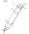
- FIG. 1 is a view showing an external appearance of the displacement measuring apparatus according to an embodiment of the invention.
- the displacement measuring apparatus 10 is capable of measuring the amount of the wire 12 led into or taken out of the body of the apparatus.
- the measured amount of the wire 12 led into or taken out of the body of the apparatus can be converted into an electrical signal.
- the measured value converted into the electrical signal is transmitted to another apparatus through a cable 14.
- Fixing belts 16 are used for fixing the displacement measuring apparatus 10 onto another apparatus.
- FIG. 2 is a schematic diagram of the displacement measuring apparatus 10.
- the displacement measuring apparatus 10 is provided with transmission pulleys 18, 20, an encoder 22, fixed pulleys 24, 26, 28, movable pulleys 30, 32, 34, 36, and a linear sensor (line sensor) 38. Further, a common wire 12 is passed around all the above elements.
- the transmission pulleys 18 and 20 are capable of transmitting the wire 12 to other elements.
- the encoder 22 allows measurement to be made by its amount of rotation.
- the fixed pulleys 24, 26, and 28 are fixed to the body of the displacement measuring apparatus 10.
- the movable pulleys 30, 32, 34, and 36 are movable in the directions of the arrowheads indicated in FIG. 2.
- the linear sensor 38 is disposed between the movable pulleys and the fixed pulleys. The linear sensor allows the movement (displacement) of the movable pulleys 30, 32, 34, and 36 in the direction X to be measured by a change in the resistance value.
- FIG. 3 is a sectional view of the displacement measuring apparatus of FIG. 1 in the vertical direction.
- the wire 12 is allowed to pass through the led-out 40 and pass through the clean region 42.
- the wire 12 can be made clean of foreign objects and mud attached thereto.
- the wire 12 can also be coated with a resin or the like so that a clogging is prevented. Scraping the foreign matters off the rope can also be achieved by an O-ring made of a resin or the like.
- the displacement measuring apparatus 10 may be provided with a sealed oil reservoir so that moisture is removed. Thereby, the apparatus is rendered more maintenance-free than before.
- FIG. 4 is a view in the direction of the arrows A-A in FIG. 3.
- the wire 12 passed through the clean region 42 reaches the transmission pulley 20 through the transmission pulley 18.
- the wire 12 arrived at the transmission pulley 20 is passed around the encoder 22.
- FIG. 5 is a sectional view in the horizontal direction of the displacement measuring apparatus shown in FIG. 1.
- the wire 12 passed around the encoder 22 is passed around the pulley 30.
- the wire 12 passed around the pulley 30 is passed around the fixed pulley 24.
- the wire 12 passed around the fixed pulley 24 is passed around the movable pulley 32.
- the wire 12 passed around the movable pulley 32 is passed around the fixed pulley 26.
- the wire 12 passed around the fixed pulley 26 is passed around the movable pulley 34.
- the wire 12 passed around the movable pulley 34 is passed around the fixed pulley 28.
- the wire 12 passed around the fixed pulley 28 is passed around the movable pulley 36.
- the wire 12 passed around the movable pulley 36 is fixed at its one end to a pulley supporting member 44.
- the movable pulleys 30, 32, 34, and 36 are rotatably supported by a pulley energizing portion 45 provided on the pulley supporting member 44.
- the pulley supporting member 44 is capable of moving in the directions of the arrowheads X in FIG. 5 along a guide 48.
- the fixed pulley 24, 26, and 28 are rotatably supported by a fixing member 46.
- a spring 50 between the pulley supporting member 44 and the fixing member 46 so that the movable pulleys 30, 32, 34, and 36 are given an energizing force through the pulley supporting member 44 (the spring 50 is not shown in FIG. 2 and FIG. 4 to simplify the illustration).
- the spring 50 is an example of energizing means.
- the wire 12 When the other end of the wire 12 is subjected to a pulling force, the wire 12 is activated to move the pulley supporting member 44. With the movement of the pulley supporting member 44, the movable pulleys 30, 32, 34, and 36 also move.
- the shifted amount or displacement of each of the movable pulleys 30, 32, 34, and 36 is small as compared with the let out amount of the wire 12, durability of the energizing portion 45 for energizing the movable pulleys 30, 32, 34, and 36 and the pulley supporting member 44 is improved.
- the wire 12 when the wire 12 is subjected to a pulling force, the wire 12 is led out of the measuring apparatus 10 through the led-out 40.
- the tension to the wire 12 is transmitted through the pulleys so that the pulley supporting member 44 is moved in the directions of the arrowheads in FIG. 3 against the energizing force of the spring 50.
- the linear sensor 38 detects a change in the resistance value so that the shifted amount of the pulley supporting member 44 is detected.
- the encoder 22 may be used instead of the linear sensor 38 to measure the let out amount of the wire 12.
- the encoder 22 for making incremental measurement may be used in addition to the linear sensor 38 which makes absolute measurement, so that the let out amount of the wire 12 is measured by "pseudo-absolute". Since the let out amount of the wire 12 can be measured more finely by means of the encoder 22, combination of it with the linear sensor 38 allows more precise measurement of the let out amount to be made without changing the measurable let out amount of the wire 12.
- the encoder 22 When the encoder 22 is used, light is picked up by a pick-up device 52 to thereby measure the angle of rotation of the encoder 22. By detecting the angle of rotation of the encoder 22 by passing the wire 12 around the encoder 22, the let out amount of the wire 12 can be measured.
- the wire slips at the portion where it is passed around so that the movement of the wire becomes unable to be accurately represented by the encoder.
- the timing belt here is such a belt that is made of a resin with recesses and protrusions regularly formed thereon.
- FIG. 7 is a schematic diagram showing a mechanism for transmitting the let out amount of the wire to the encoder, as another embodiment of the present invention.
- FIG. 8 is a diagram partly showing an enlarged timing belt.
- the mechanism for transmitting the let out amount of the wire 12 to the encoder 122 is formed of timing belt pulleys 80, 82, a timing belt 78, and pulley supporting member 144.
- To the pulley supporting member 144 are attached movable pulleys 30, 32, 34, and 36. By letting out or letting in the wire 12 thereby moving the movable pulleys 30, 32, 34, and 36, the pulley supporting member 144 is moved in the directions of the arrowheads X.
- the timing belt pulley 80 is attached to the encoder 122.
- the timing belt pulley 82 is rotatably attached to the displacement measuring apparatus.
- the timing belt 78 is passed around the timing belt pulleys 80, 82.
- the timing belt 78 is provided with regular recesses and protrusions as shown in FIG. 8.
- the timing belt pulleys 80 and 82 are formed so as to engage the timing belt 78.
- the pulley supporting member 144 is provided with a belt fixing portion 145.
- the belt fixing portion 145 is fixed to a portion of the timing belt 78.
- the mechanism for letting out or letting in the wire is configured as described above, when the pulley supporting member 144 is moved in the directions X, the shifted amount is converted into the rotated amount of the encoder by means of the timing belt 78 and the timing pulley 80.
- timing belt 78 and the timing belt pulleys 80 and 82 are arranged to engage with each other, no slippage occurs.
- the displacement measuring apparatus of the present invention can be applied to various types of displacement measurement.
- the displacement measuring apparatus according to the invention can be used as a displacement measuring apparatus of the stroke of a hydraulic cylinder of heavy machinery.
- FIG. 6 is a diagram showing an example of an shovel-car (heavy machine) provided with the displacement measuring apparatus of the invention.
- a ground revealing tool (bucket) 58 of such a machine as an excavator (shovel-car) 56 is supported by a stick 60 and a boom 62 for rotation in specific directions and operated by cylinders 64, 66, and 68 each of which is extended and retracted by hydraulic pressure.
- the angle at a joint portion can be obtained by measuring the lengths of the three sides of the triangle including the fulcrum at each joint.
- FIG. 6 an embodiment of a shovel-car with a displacement measuring apparatus of the invention attached thereto will be described.
- the shovel-car 56 is made up of the shovel-car body 70, boom 62, stick (arm) 60, and the bucket 58.
- the hydraulic cylinder 64 is disposed between the shovel-car body 70 and the boom 62.
- the hydraulic cylinder 66 is disposed between the boom 62 and the stick 60.
- the hydraulic cylinder 68 is disposed between the stick 60 and the bucket 58.
- the hydraulic cylinder 64 extends and retracts the cylinder rod so as to move the boom 62.
- the hydraulic cylinder 66 extends and retracts the cylinder rod so as to move the stick 60.
- the hydraulic cylinder 68 extends and retracts the cylinder rod so as to move the bucket 58.
- a level sensor 72 To the shovel-car body 70 is attached a level sensor 72. On the ground surface 76 near the shovel-car 56, there is disposed a rotating laser 74. A laser beam from the rotating laser 74 is sensed by a level sensor 72. The level sensor 72 sensing the laser beam from the rotating laser 74 is capable of level setting or gradient setting.
- the displacement measuring apparatus of the invention can be installed on each of the hydraulic cylinders 64, 66, and 68. Namely, each of them can use the displacement measuring apparatus as a boom sensor, a stick sensor (arm sensor), and a bucket sensor.
- the displacement measuring apparatus of the invention can be made into a smaller and narrower form, and hence it is easy to install and interference of the apparatus with other portion of the shovel-car 56 can be avoided. Therefore, the stroke amount (i.e., displacement) of each of the hydraulic cylinders 64, 66, and 68 can be easily measured by the displacement measuring apparatus of the invention. As described above, the relative angle between the shovel-car body 70 and the boom 62, the relative angle between the boom 62 and the stick 60, and the relative angle between the stick 60 and the bucket 58 can be detected from the stroke amount of each hydraulic cylinder (i.e., displacement).
- linear sensor is not limited to the one of the above described type.
- An optical line sensor (CCD, LED) may also be used. It is also possible to measure the linear displacement by having a pressure sensor attached to the spring portion.
- the present invention is not limited to the mode in which the displacement measuring apparatus is used as the cylinder stroke measuring apparatus. It can be applied to measurement of other displacement. Of course, the invention is not limited to measurement of stroke amount of hydraulic cylinders.
- the apparatus can be formed smaller. It is also possible to provide the apparatus in a slender form.
- the apparatus in a slender form facilitates its installation on, for example, a heavy machine, and avoids its interference with other part. Because of ease of installation, the days required for installation can be decreased.
- the displacement of each pulley is small as compared with the let out amount of the wire.
- only light load is placed on the energizing portion for energizing the pulleys, and, hence, endurance of the energizing portion is improved. Therefore, accuracy of the displacement measuring apparatus can be prevented from deteriorating.
Landscapes
- Physics & Mathematics (AREA)
- General Physics & Mathematics (AREA)
- A Measuring Device Byusing Mechanical Method (AREA)
- Length Measuring Devices With Unspecified Measuring Means (AREA)
- Operation Control Of Excavators (AREA)
Applications Claiming Priority (2)
| Application Number | Priority Date | Filing Date | Title |
|---|---|---|---|
| JP6765099 | 1999-03-15 | ||
| JP11067650A JP2000266503A (ja) | 1999-03-15 | 1999-03-15 | 変位測定装置 |
Publications (2)
| Publication Number | Publication Date |
|---|---|
| EP1037007A2 true EP1037007A2 (de) | 2000-09-20 |
| EP1037007A3 EP1037007A3 (de) | 2002-01-02 |
Family
ID=13351124
Family Applications (1)
| Application Number | Title | Priority Date | Filing Date |
|---|---|---|---|
| EP00104939A Withdrawn EP1037007A3 (de) | 1999-03-15 | 2000-03-08 | Verschiebungsmessapparat |
Country Status (3)
| Country | Link |
|---|---|
| US (1) | US6442862B1 (de) |
| EP (1) | EP1037007A3 (de) |
| JP (1) | JP2000266503A (de) |
Cited By (1)
| Publication number | Priority date | Publication date | Assignee | Title |
|---|---|---|---|---|
| CN103234459A (zh) * | 2013-04-27 | 2013-08-07 | 济南时代试金试验机有限公司 | 一种试验机位移测量及限位装置 |
Families Citing this family (6)
| Publication number | Priority date | Publication date | Assignee | Title |
|---|---|---|---|---|
| US6946968B1 (en) * | 2003-09-24 | 2005-09-20 | Johnson Clifford C | Hydraulic stroke measuring system |
| DE10361699B3 (de) * | 2003-12-30 | 2005-10-13 | Asm Automation Sensorik Messtechnik Gmbh | Messseil-Wegsensor mit Feder in der Seiltrommel |
| US20100186258A1 (en) * | 2009-01-27 | 2010-07-29 | Garza Sandra D | Shoe and boot construction with attachable components |
| US9888738B2 (en) * | 2010-12-01 | 2018-02-13 | Magic Land Limited | Slipper body and slipper with an ornament |
| CN109736374A (zh) * | 2019-01-25 | 2019-05-10 | 北京百度网讯科技有限公司 | 用于控制设备的方法和装置 |
| CN119491518B (zh) * | 2025-01-15 | 2025-04-15 | 中国水利水电第九工程局有限公司 | 施工过程中高边坡动态监测系统及方法 |
Family Cites Families (8)
| Publication number | Priority date | Publication date | Assignee | Title |
|---|---|---|---|---|
| US3747218A (en) * | 1971-02-10 | 1973-07-24 | L Bell | Apparatus for automatically measuring pipe running into or out of a well |
| GB2045196B (en) * | 1979-03-31 | 1982-12-08 | Ferranti Ltd | Cable tensioning device |
| US4688555A (en) * | 1986-04-25 | 1987-08-25 | Circon Corporation | Endoscope with cable compensating mechanism |
| US4903536A (en) * | 1988-04-21 | 1990-02-27 | Massachusetts Institute Of Technology | Compact cable transmission with cable differential |
| SE506213C2 (sv) * | 1996-03-20 | 1997-11-24 | Johansson Ab C E | Anordning för att åstadkomma en i huvudsak rätlinjig rörelse hos en rörlig del i en mätmaskin där kraftöverföringen sker från en typ av rörelse till den linjära rörelsen |
| US6253461B1 (en) * | 1996-11-05 | 2001-07-03 | David C. Fischer | Casting rod and reel with distance meter |
| IT1287147B1 (it) * | 1996-11-08 | 1998-08-04 | Pfisterer Srl | Dispositivo compensatore delle variazioni di lunghezza di funi tesate,con tiro sostanzialmente costante |
| JP2913628B1 (ja) * | 1998-07-27 | 1999-06-28 | 西松建設株式会社 | 地中連続壁掘削機の位置検出装置 |
-
1999
- 1999-03-15 JP JP11067650A patent/JP2000266503A/ja active Pending
-
2000
- 2000-03-08 EP EP00104939A patent/EP1037007A3/de not_active Withdrawn
- 2000-03-09 US US09/521,608 patent/US6442862B1/en not_active Expired - Fee Related
Cited By (1)
| Publication number | Priority date | Publication date | Assignee | Title |
|---|---|---|---|---|
| CN103234459A (zh) * | 2013-04-27 | 2013-08-07 | 济南时代试金试验机有限公司 | 一种试验机位移测量及限位装置 |
Also Published As
| Publication number | Publication date |
|---|---|
| US6442862B1 (en) | 2002-09-03 |
| EP1037007A3 (de) | 2002-01-02 |
| JP2000266503A (ja) | 2000-09-29 |
Similar Documents
| Publication | Publication Date | Title |
|---|---|---|
| CN100387504C (zh) | 具有外部标记的升运带 | |
| CA2604819C (en) | Method of applying a strain sensor to a cylindrical structure | |
| KR101093390B1 (ko) | 조정 부재 | |
| CA2418099A1 (en) | Displacement measurement with a spring and force measurement for actuators, blow-out preventers, valves | |
| CN101057060B (zh) | 测量井筒内部尺寸的装置及包括该装置的系统和测井工具 | |
| US20080035324A1 (en) | Integrated measurement based on an optical pattern-recognition | |
| WO1997023772B1 (en) | Structural monitoring sensor system | |
| US6442862B1 (en) | Displacement measuring apparatus | |
| DE69823026T2 (de) | Integrierter resonanter mikrostruktur-sensor für hohe temperaturen | |
| CA2129391A1 (en) | Depth measurement of slickline | |
| AU2004223478B2 (en) | Wireline subsea metering head and method of use | |
| WO2011159659A1 (en) | Measurement device and a system and method for using the same | |
| US20160273560A1 (en) | Fluid cylinder | |
| GB2296001A (en) | Winch apparatus | |
| US6357132B1 (en) | Boom position detection system | |
| US6637118B2 (en) | Rotary encoder | |
| CN112985321A (zh) | 用于校准方位/位置传感器的方法 | |
| DE112004001038T5 (de) | Optischer Verschiebungs-Drehmomentsensor | |
| US20230266554A1 (en) | System for applying pre-strain to an optical sensor | |
| US4951505A (en) | Block position sensor | |
| US20230038939A1 (en) | Installation of optical sensors for use in traffic monitoring | |
| KR20100086530A (ko) | 볼트의 연신율 측정 장치 | |
| KR19990003729A (ko) | 엔코더를 이용한 길이 변형량 자동 측정장치 및 그 방법 | |
| US3390574A (en) | Ton-mile marker | |
| FI90905B (fi) | Sovitelma kallioporakoneen syöttöpalkin aseman mittaamiseksi ja/tai porakoneen aseman mittaamiseksi |
Legal Events
| Date | Code | Title | Description |
|---|---|---|---|
| PUAI | Public reference made under article 153(3) epc to a published international application that has entered the european phase |
Free format text: ORIGINAL CODE: 0009012 |
|
| AK | Designated contracting states |
Kind code of ref document: A2 Designated state(s): DE SE Kind code of ref document: A2 Designated state(s): AT BE CH CY DE DK ES FI FR GB GR IE IT LI LU MC NL PT SE |
|
| AX | Request for extension of the european patent |
Free format text: AL;LT;LV;MK;RO;SI |
|
| PUAL | Search report despatched |
Free format text: ORIGINAL CODE: 0009013 |
|
| AK | Designated contracting states |
Kind code of ref document: A3 Designated state(s): AT BE CH CY DE DK ES FI FR GB GR IE IT LI LU MC NL PT SE |
|
| AX | Request for extension of the european patent |
Free format text: AL;LT;LV;MK;RO;SI |
|
| 17P | Request for examination filed |
Effective date: 20020620 |
|
| AKX | Designation fees paid |
Free format text: DE SE |
|
| STAA | Information on the status of an ep patent application or granted ep patent |
Free format text: STATUS: THE APPLICATION IS DEEMED TO BE WITHDRAWN |
|
| 18D | Application deemed to be withdrawn |
Effective date: 20041001 |