EP1036617A2 - Ein Drehverfahren und Drehmaschine - Google Patents
Ein Drehverfahren und Drehmaschine Download PDFInfo
- Publication number
- EP1036617A2 EP1036617A2 EP00850046A EP00850046A EP1036617A2 EP 1036617 A2 EP1036617 A2 EP 1036617A2 EP 00850046 A EP00850046 A EP 00850046A EP 00850046 A EP00850046 A EP 00850046A EP 1036617 A2 EP1036617 A2 EP 1036617A2
- Authority
- EP
- European Patent Office
- Prior art keywords
- procedure
- displacement
- axis
- workpiece
- profile
- Prior art date
- Legal status (The legal status is an assumption and is not a legal conclusion. Google has not performed a legal analysis and makes no representation as to the accuracy of the status listed.)
- Withdrawn
Links
- 238000000034 method Methods 0.000 title claims abstract description 34
- 238000007514 turning Methods 0.000 title claims abstract description 21
- 238000006073 displacement reaction Methods 0.000 claims abstract description 26
- 230000007547 defect Effects 0.000 abstract 1
- 238000003754 machining Methods 0.000 description 4
- 238000005520 cutting process Methods 0.000 description 2
- 238000010586 diagram Methods 0.000 description 2
- 230000000694 effects Effects 0.000 description 2
- 238000004519 manufacturing process Methods 0.000 description 2
- 230000001419 dependent effect Effects 0.000 description 1
- 230000008030 elimination Effects 0.000 description 1
- 238000003379 elimination reaction Methods 0.000 description 1
- 238000005516 engineering process Methods 0.000 description 1
- 238000012986 modification Methods 0.000 description 1
- 230000004048 modification Effects 0.000 description 1
Images
Classifications
-
- B—PERFORMING OPERATIONS; TRANSPORTING
- B23—MACHINE TOOLS; METAL-WORKING NOT OTHERWISE PROVIDED FOR
- B23Q—DETAILS, COMPONENTS, OR ACCESSORIES FOR MACHINE TOOLS, e.g. ARRANGEMENTS FOR COPYING OR CONTROLLING; MACHINE TOOLS IN GENERAL CHARACTERISED BY THE CONSTRUCTION OF PARTICULAR DETAILS OR COMPONENTS; COMBINATIONS OR ASSOCIATIONS OF METAL-WORKING MACHINES, NOT DIRECTED TO A PARTICULAR RESULT
- B23Q1/00—Members which are comprised in the general build-up of a form of machine, particularly relatively large fixed members
- B23Q1/25—Movable or adjustable work or tool supports
- B23Q1/44—Movable or adjustable work or tool supports using particular mechanisms
- B23Q1/56—Movable or adjustable work or tool supports using particular mechanisms with sliding pairs only, the sliding pairs being the first two elements of the mechanism
- B23Q1/60—Movable or adjustable work or tool supports using particular mechanisms with sliding pairs only, the sliding pairs being the first two elements of the mechanism two sliding pairs only, the sliding pairs being the first two elements of the mechanism
-
- B—PERFORMING OPERATIONS; TRANSPORTING
- B23—MACHINE TOOLS; METAL-WORKING NOT OTHERWISE PROVIDED FOR
- B23B—TURNING; BORING
- B23B3/00—General-purpose turning-machines or devices, e.g. centre lathes with feed rod and lead screw; Sets of turning-machines
- B23B3/06—Turning-machines or devices characterised only by the special arrangement of constructional units
-
- B—PERFORMING OPERATIONS; TRANSPORTING
- B23—MACHINE TOOLS; METAL-WORKING NOT OTHERWISE PROVIDED FOR
- B23Q—DETAILS, COMPONENTS, OR ACCESSORIES FOR MACHINE TOOLS, e.g. ARRANGEMENTS FOR COPYING OR CONTROLLING; MACHINE TOOLS IN GENERAL CHARACTERISED BY THE CONSTRUCTION OF PARTICULAR DETAILS OR COMPONENTS; COMBINATIONS OR ASSOCIATIONS OF METAL-WORKING MACHINES, NOT DIRECTED TO A PARTICULAR RESULT
- B23Q1/00—Members which are comprised in the general build-up of a form of machine, particularly relatively large fixed members
- B23Q1/25—Movable or adjustable work or tool supports
- B23Q1/44—Movable or adjustable work or tool supports using particular mechanisms
- B23Q1/56—Movable or adjustable work or tool supports using particular mechanisms with sliding pairs only, the sliding pairs being the first two elements of the mechanism
- B23Q1/60—Movable or adjustable work or tool supports using particular mechanisms with sliding pairs only, the sliding pairs being the first two elements of the mechanism two sliding pairs only, the sliding pairs being the first two elements of the mechanism
- B23Q1/62—Movable or adjustable work or tool supports using particular mechanisms with sliding pairs only, the sliding pairs being the first two elements of the mechanism two sliding pairs only, the sliding pairs being the first two elements of the mechanism with perpendicular axes, e.g. cross-slides
- B23Q1/621—Movable or adjustable work or tool supports using particular mechanisms with sliding pairs only, the sliding pairs being the first two elements of the mechanism two sliding pairs only, the sliding pairs being the first two elements of the mechanism with perpendicular axes, e.g. cross-slides a single sliding pair followed perpendicularly by a single sliding pair
Definitions
- the present invention relates to a turning procedure as described in the preamble to claim 1.
- the cutting edge of the lathe tool When turning a surface such as the concave surface of a ball bearing ring, the cutting edge of the lathe tool must describe a correspondingly curved path. This is generally achieved by the tool being displaceable along two lines located perpendicular to each other, with drive means and means for transferring motion for each displacement.
- the curvature of the surface to be turned forces the movement of the tool along at least one of the two lines to take place in two different directions, i.e. the movement turns and changes sign.
- Such a turning operation can be performed, for instance, in a CNC controlled lathe or combined machine where the machining is based on interpolation technology.
- the lathe tool must then move in accordance with a path defined in the control program and effect cutting in the workpiece which geometrically follows the programmed path.
- the drive means of the machine slide which in most cases consist of lead screws made with as little clearance as possible by means of prestressed balls or rollers, must thus alter their direction of movement. Two main effects result when the direction of movement and thus the direction of rotation of the lead screw are altered:
- the object of the present invention is to provide a method of turning wherein the above-mentioned error is eliminated.
- the procedure thus in practice provides a faultless machining surface that is sufficiently smooth to eliminate the need for subsequent grinding even when the most extreme demands are placed on surface uniformity.
- the procedure is used for manufacturing a ring for a ball bearing or roller bearing. Machining of the ball race is a case in which the demands for surface uniformity are extremely high and, with conventional turning, the concave shape of the ball race necessitates the above-mentioned change of direction.
- the two displacement lines are perpendicular to each other, and this is therefore a suitable embodiment in most cases and constitutes a preferred embodiment of the invention.
- the machine surface is strongly profiled, e.g. when the profile is an arc with more than 90° arc angle, a change of direction cannot be avoided unless the displacement axes form an angle with each other that is not a right-angle.
- This therefore constitutes an alternative preferred embodiment of the invention that permits error elimination even in the case of strongly curved surfaces.
- the relative orientation between the displacement lines on the one hand and the axis of rotation on the other hand can easily be achieved by inclining either the axis of rotation or the displacement lines. Special variants for the orientation therefore constitute preferred embodiments of the invention.
- the invention also relates to a lathe for performing the procedure according to the invention, as well as objects manufactured in accordance with the procedure.
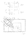
- FIGs 1 and 2 are intended to illustrate the problem and the principle solution according to the invention, where Figure 1 shows the principle of conventional turning and Figure 2 turning in accordance with the invention.
- Figure 1 shows a workpiece 101 which, during turning of the surface 102, rotates about the axis y.
- the surface 102 has the profile of an arc stretching between the end points A and B.
- the radial distance r thus varies continuously between the end points A and B.
- the lathe tool 103 is moved along a pre-programmed path from point A to point B. This is achieved by the tool being displaced in the x direction by first drive means and in the z direction by second drive means.
- Displacement in the z direction occurs unidirectionally downwards.
- Displacement in the x direction occurs first in positive direction, i.e. to the right in the figure, after which it turns at the bottom of the profile and occurs in negative direction.
- the square step error described in the introduction will inevitably occur at the change in direction.
- Figure 2 shows an equivalent workpiece 1 where the co-ordinate system for the displacement lines of the lathe tool is inclined in relation to the axis of rotation y.
- the lathe tool is moved by being driven along two lines.
- not only the movement in z direction but also that in x direction then becomes unidirectional.
- the movement in x direction thus continues in positive direction right up to the end point B, even upon passage of the bottom of the profile 2.
- Figure 3 is a diagram of a lathe operating in accordance with the procedure according to the invention.
- the workpiece 1 is placed on a table 4 rotating about the vertical axis y.
- the lathe tool 3 is controlled by a drive unit 6 in a stand 5.
- the drive unit 6 comprises drive means for displacing the lathe tool 3 in two orthogonal directions. As can be seen, the drive unit is oriented obliquely so that the z direction forms an angle with the horizontal plane and the x direction consequently forms a corresponding angle with the vertical plane.
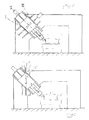
- the drive unit comprises a system for driving the tool 3 in either the x or the z direction.
- a machine slide 10 is displaceable in z direction via a lead screw 11, by means of a first drive motor 12.
- the machine slide 10 carries a tool holder 13, to which the lathe tool 3 is attached.
- the machine slide 10 is guided along tracks 14.
- the drive system for the z movement is mounted in a second machine slide 7 which is displaceable in x direction by means of a second drive motor 9 via a lead screw 8 and guided by tracks 15.
- the movements are pre-programmed in known manner and the movement of the tool is unidirectional in both x and z direction, as described with reference to Figure 2.
- the drive unit may be oriented purely horizontally or vertically and the table 2 instead inclined so that the y axis becomes inclined. A combination is naturally also possible.
- FIG. 3 The procedure illustrated in Figure 3 is shown in conjunction with a lathe that is fixed in the direction of the drive unit, at an oblique angle ⁇ of 45°.
- Figure 4 shows an embodiment in which the drive unit can assume three different fixed positions I, II and III with an oblique angle ⁇ of 30°, 45° and 60°, respectively, for instance. The most suitable of these is chosen depending on the appearance of the profile.
- the procedure can advantageously be used in a lathe where the oblique angle of the drive unit can be set at an optional angle ⁇ between the extreme positions I and III, whereupon an optimal angle value can be used.
- Figure 5 shows an embodiment in which the displacement lines z and x 1 are not orthogonal.
- a deeper profile can be turned in this embodiment.
- an arc-shaped profile for instance, an arc of up to about 135° arc angle can be machine with the illustrated angle between the z and x axes, without a change of direction in any of the directions.
Landscapes
- Engineering & Computer Science (AREA)
- Mechanical Engineering (AREA)
- Turning (AREA)
Applications Claiming Priority (2)
| Application Number | Priority Date | Filing Date | Title |
|---|---|---|---|
| SE9900988 | 1999-03-16 | ||
| SE9900988A SE513774C2 (sv) | 1999-03-16 | 1999-03-16 | Förfarande för svarvning, objekt framställt genom förfarandet och svarv för genomförande av förfarandet |
Publications (2)
| Publication Number | Publication Date |
|---|---|
| EP1036617A2 true EP1036617A2 (de) | 2000-09-20 |
| EP1036617A3 EP1036617A3 (de) | 2003-07-23 |
Family
ID=20414905
Family Applications (1)
| Application Number | Title | Priority Date | Filing Date |
|---|---|---|---|
| EP00850046A Withdrawn EP1036617A3 (de) | 1999-03-16 | 2000-03-16 | Ein Drehverfahren und Drehmaschine |
Country Status (2)
| Country | Link |
|---|---|
| EP (1) | EP1036617A3 (de) |
| SE (1) | SE513774C2 (de) |
Cited By (2)
| Publication number | Priority date | Publication date | Assignee | Title |
|---|---|---|---|---|
| US7597033B2 (en) * | 2005-05-06 | 2009-10-06 | Satisloh Gmbh | Machine for machining optical workpieces, in particular plastic spectacle lenses |
| CN104858453A (zh) * | 2015-06-08 | 2015-08-26 | 含山县朝霞铸造有限公司 | 一种旋转伸缩圆心扁心凸轮刀台座 |
Family Cites Families (3)
| Publication number | Priority date | Publication date | Assignee | Title |
|---|---|---|---|---|
| US4625377A (en) * | 1983-12-20 | 1986-12-02 | Kavthekar Keshav S | Method for manufacturing universal joints |
| SU1484436A1 (ru) * | 1987-04-28 | 1989-06-07 | Новополоцкий Политехнический Институт Им.Ленинского Комсомола Белоруссии | Способ токарной обработки криволинейных поверхностей |
| CH674325A5 (en) * | 1987-10-26 | 1990-05-31 | Max Gfeller Ag | Machine for producing workpieces with concave or convex surfaces - has table which can be swung about vertical axis and carrying slide which carries workpiece |
-
1999
- 1999-03-16 SE SE9900988A patent/SE513774C2/sv not_active IP Right Cessation
-
2000
- 2000-03-16 EP EP00850046A patent/EP1036617A3/de not_active Withdrawn
Cited By (2)
| Publication number | Priority date | Publication date | Assignee | Title |
|---|---|---|---|---|
| US7597033B2 (en) * | 2005-05-06 | 2009-10-06 | Satisloh Gmbh | Machine for machining optical workpieces, in particular plastic spectacle lenses |
| CN104858453A (zh) * | 2015-06-08 | 2015-08-26 | 含山县朝霞铸造有限公司 | 一种旋转伸缩圆心扁心凸轮刀台座 |
Also Published As
| Publication number | Publication date |
|---|---|
| SE9900988D0 (sv) | 1999-03-16 |
| SE513774C2 (sv) | 2000-11-06 |
| SE9900988L (sv) | 2000-09-17 |
| EP1036617A3 (de) | 2003-07-23 |
Similar Documents
| Publication | Publication Date | Title |
|---|---|---|
| US6918326B2 (en) | Vertical lathe | |
| US20220395944A1 (en) | Multi-degree-of-freedom numerical control turntable | |
| CN102019571B (zh) | 复杂曲面自适应磨抛加工机床 | |
| US4739684A (en) | Apparatus for finishing pistons and the like and method therefor | |
| CN1498716A (zh) | 刀具转塔和机床 | |
| CN110625395A (zh) | 一种双主轴车铣复合机床 | |
| CN102554745A (zh) | 一种轴承内圈滚道和锁口的磨削装置及磨削方法 | |
| JP4953599B2 (ja) | 加工物のプロファイルの研削方法及び研削装置 | |
| JP2000501656A (ja) | 回転フライス加工のための方法と装置 | |
| EP1036617A2 (de) | Ein Drehverfahren und Drehmaschine | |
| JP2000515075A (ja) | 極座標運動を行う3軸旋盤 | |
| US4867020A (en) | Apparatus for finishing pistons and the like and method therefor | |
| CN119634950B (zh) | 一种胀断连杆裂解槽激光加工装置及加工方法 | |
| CN2616325Y (zh) | 一种加工弧面凸轮及复杂曲面零件用数控铣床 | |
| CN1028621C (zh) | 轧辊螺纹槽加工方法及加工机床 | |
| CN111496272A (zh) | 一种金属零件切削装置 | |
| CN1298500C (zh) | 三主轴双门架双驱动五联动复合加工中心 | |
| CN1088863A (zh) | 以四轴数控机床加工分度凸轮的制造方法及其装置 | |
| JP3612887B2 (ja) | スクロール板のシール溝および壁面の加工方法 | |
| CN1921973A (zh) | 制造接合配件的成型槽的方法 | |
| CN113245638A (zh) | 一种用于立式铣床加工弧齿锥齿轮的夹具 | |
| KR102761962B1 (ko) | 정밀부품 가공을 위한 밀링머신용 미세조정 지그 | |
| KR102824842B1 (ko) | 머시닝센터의 가공 헤드 위치보정장치 | |
| CN219665326U (zh) | 一种滚珠丝杠副螺母滚珠循环路电解加工设备 | |
| JP3334291B2 (ja) | 横形ブローチ盤 |
Legal Events
| Date | Code | Title | Description |
|---|---|---|---|
| PUAI | Public reference made under article 153(3) epc to a published international application that has entered the european phase |
Free format text: ORIGINAL CODE: 0009012 |
|
| AK | Designated contracting states |
Kind code of ref document: A2 Designated state(s): AT BE CH CY DE DK ES FI FR GB GR IE IT LI LU MC NL PT SE |
|
| AX | Request for extension of the european patent |
Free format text: AL;LT;LV;MK;RO;SI |
|
| PUAL | Search report despatched |
Free format text: ORIGINAL CODE: 0009013 |
|
| RIC1 | Information provided on ipc code assigned before grant |
Ipc: 7B 23Q 1/62 B Ipc: 7B 23Q 1/60 B Ipc: 7B 23B 3/06 B Ipc: 7B 23B 1/00 A |
|
| AK | Designated contracting states |
Designated state(s): AT BE CH CY DE DK ES FI FR GB GR IE IT LI LU MC NL PT SE |
|
| AX | Request for extension of the european patent |
Extension state: AL LT LV MK RO SI |
|
| 17P | Request for examination filed |
Effective date: 20040123 |
|
| AKX | Designation fees paid |
Designated state(s): AT BE CH CY DE DK ES FI FR GB GR IE IT LI LU MC NL PT SE |
|
| R17P | Request for examination filed (corrected) |
Effective date: 20040123 |
|
| 17Q | First examination report despatched |
Effective date: 20050401 |
|
| STAA | Information on the status of an ep patent application or granted ep patent |
Free format text: STATUS: THE APPLICATION IS DEEMED TO BE WITHDRAWN |
|
| 18D | Application deemed to be withdrawn |
Effective date: 20060110 |