EP1035416A2 - MR-Verfahren - Google Patents
MR-Verfahren Download PDFInfo
- Publication number
- EP1035416A2 EP1035416A2 EP00200801A EP00200801A EP1035416A2 EP 1035416 A2 EP1035416 A2 EP 1035416A2 EP 00200801 A EP00200801 A EP 00200801A EP 00200801 A EP00200801 A EP 00200801A EP 1035416 A2 EP1035416 A2 EP 1035416A2
- Authority
- EP
- European Patent Office
- Prior art keywords
- magnetic field
- stationary magnetic
- frequency
- stationary
- esr
- Prior art date
- Legal status (The legal status is an assumption and is not a legal conclusion. Google has not performed a legal analysis and makes no representation as to the accuracy of the status listed.)
- Withdrawn
Links
- 238000001646 magnetic resonance method Methods 0.000 title 1
- 230000005415 magnetization Effects 0.000 claims abstract description 36
- 238000000034 method Methods 0.000 claims abstract description 16
- 230000005284 excitation Effects 0.000 claims abstract description 3
- 238000004435 EPR spectroscopy Methods 0.000 claims description 28
- 238000002474 experimental method Methods 0.000 claims description 12
- 239000008280 blood Substances 0.000 claims description 4
- 210000004369 blood Anatomy 0.000 claims description 4
- 239000002872 contrast media Substances 0.000 claims description 3
- 230000004936 stimulating effect Effects 0.000 claims description 2
- 230000000717 retained effect Effects 0.000 abstract description 2
- 238000003384 imaging method Methods 0.000 abstract 1
- 230000000694 effects Effects 0.000 description 4
- 239000004020 conductor Substances 0.000 description 3
- 230000003993 interaction Effects 0.000 description 3
- 238000011835 investigation Methods 0.000 description 2
- 238000000429 assembly Methods 0.000 description 1
- 230000000712 assembly Effects 0.000 description 1
- 210000005242 cardiac chamber Anatomy 0.000 description 1
- 230000001419 dependent effect Effects 0.000 description 1
- 238000010586 diagram Methods 0.000 description 1
- 230000008034 disappearance Effects 0.000 description 1
- 239000003574 free electron Substances 0.000 description 1
- 238000002595 magnetic resonance imaging Methods 0.000 description 1
- 230000035515 penetration Effects 0.000 description 1
- 230000010287 polarization Effects 0.000 description 1
- 230000002123 temporal effect Effects 0.000 description 1
- 230000002792 vascular Effects 0.000 description 1
Images
Classifications
-
- G—PHYSICS
- G01—MEASURING; TESTING
- G01R—MEASURING ELECTRIC VARIABLES; MEASURING MAGNETIC VARIABLES
- G01R33/00—Arrangements or instruments for measuring magnetic variables
- G01R33/20—Arrangements or instruments for measuring magnetic variables involving magnetic resonance
- G01R33/28—Details of apparatus provided for in groups G01R33/44 - G01R33/64
- G01R33/38—Systems for generation, homogenisation or stabilisation of the main or gradient magnetic field
- G01R33/381—Systems for generation, homogenisation or stabilisation of the main or gradient magnetic field using electromagnets
-
- G—PHYSICS
- G01—MEASURING; TESTING
- G01R—MEASURING ELECTRIC VARIABLES; MEASURING MAGNETIC VARIABLES
- G01R33/00—Arrangements or instruments for measuring magnetic variables
- G01R33/20—Arrangements or instruments for measuring magnetic variables involving magnetic resonance
- G01R33/62—Arrangements or instruments for measuring magnetic variables involving magnetic resonance using double resonance
Definitions
- the invention also relates to an arrangement for carrying out such an arrangement Procedure.
- a second stationary one works Magnetic field onto the nuclei previously influenced by the first magnetic field, and at least one MR experiment is then carried out in the usual manner.
- the second stationary magnetic field can be much weaker than the first, but requires sufficient homogeneity for performing MR examinations.
- the resulting magnetic field remains increased nuclear magnetization exist for a while, and the associated improved signal / noise ratio can be exploited if under the influence of the second stationary magnetic field at a close time interval to the first stationary Magnetic field that the MR experiments are carried out.
- the object of the present invention is a method of the type mentioned continue to improve. This object is achieved in that the directions of the first and the second stationary magnetic field different from 0 °, preferably enclose angles of 90 ° and that the two overlap stationary magnetic fields.
- the invention is based on the knowledge that when the nuclear magnetization still during the effectiveness of the first stationary magnetic field among the Influence of the second stationary magnetic field and then the first stationary Magnetic field disappears, the nuclear magnetization vector from through the first magnetic field predetermined direction in the direction predetermined by the second magnetic field is tilted.
- a first, preferred Possibility is specified in claim 2.
- the nuclear magnetization is not a particularly strong first stationary magnetic field increases, but because that in connection with a (relatively weak) magnetic field the electron spin resonance (ESR) of a contrast medium containing unpaired electrons in the examination object is excited by an ESR radio frequency magnetic field.
- ESR electron spin resonance
- the excitation of electron spin resonance is transferred to the cores and increases the nuclear magnetization; this effect is commonly referred to as the Overhauser effect.
- the subsequent suggestion the nuclear magnetization by an MR radio frequency magnetic field in connection with generates a second (also comparatively weak) stationary magnetic field MR signals with a signal-to-noise ratio that is otherwise only found in much stronger ones Magnetic fields can be reached.
- the embodiment provided according to claim 3 has the advantage that the ESR high-frequency magnetic field penetrate deep enough into the examination area can and that because of the stronger second stationary magnetic field a better one Signal / noise ratio results.
- the frequency of the ESR high-frequency magnetic field is a factor of around 660 higher than the frequency of the MR high-frequency magnetic field.
- the ESR and MR radio frequency magnetic fields must therefore be generated with separate high-frequency coils. If the radio frequency fields would run in the same direction (which would be necessary if the two stationary magnetic fields run in the same direction), then a strong Interaction between the coils result. However, since the two stationary magnetic fields run perpendicular to each other, the two high-frequency fields can also with each of these fields are linked in time, are perpendicular to each other, whereby an interaction between the high-frequency coils generating them is avoided.
- radio frequency coils different types covering the area under investigation enclose.
- Such a configuration would be parallel to one another ESR and MR radio frequency magnetic fields either cause strong interactions between the coils or - if the diameter of the MR coil would be significantly larger than that the ESR coil - lead to a drastically reduced signal / noise ratio.
- the MR high-frequency coil and the ESR high-frequency coil enclose each other and the area of investigation very closely good signal / noise ratio, because the coils - despite their spatial proximity - mutually do not affect.
- a solenoid coil generates a magnetic field running in the direction of its axis.
- Coils that generate a magnetic field in this direction e.g. those made up of a plurality consist of circular only inductively coupled conductor loops; however, a solenoid coil offers advantages in terms of low frequencies Signal / noise ratio.
- Advantageous refinements of the ESR high-frequency coil arrangement are described in claims 9 to 11. All of these high frequency coil assemblies generate high-frequency magnetic fields perpendicular to the coil axis.
- the increased nuclear magnetization results from that the first stationary magnetic field is much stronger than the second. If that second stationary magnetic field extends in the longitudinal direction of the examination area the first stationary magnetic field with a relatively simple coil with the required Strength are generated.
- a further embodiment of the invention is described in claim 5.
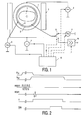
- Fig. 1 denotes a first magnet in the form of a coil 1 for generating a first stationary magnetic field B 01 , which runs perpendicular to the plane of the drawing (ie in the z direction).
- the magnetic field can have a strength of 5 mT and does not have to meet high requirements with regard to its homogeneity and stability over time.
- a second magnet 2 supplies a second stationary magnetic field B 02 , which extends in the x direction and thus perpendicular to the first stationary magnetic field B 01 .
- This magnetic field has a strength of 15 mT.
- the homogeneity and the temporal constancy of this magnetic field must meet the high requirements that generally arise for MR devices.
- the currents for the magnets 1 and 2 are supplied by current sources 3 and 4, which can be switched on and off by a control unit 15.
- An ESR coil 5 which extends in a cylindrical shape perpendicular to the plane of the drawing, generates an ESR high-frequency magnetic field in an examination area in which the object 7 to be examined is located.
- the ESR coil 5 must generate a high-frequency magnetic field perpendicular to the first stationary magnetic field B 01 in order to saturate the electron spin resonance of the free (unpaired) electrons contained in a contrast medium injected into the object 7.
- the ESR coil 5 is preferably a quadrature coil of the so-called birdcage type. As is known, this has conductors on a cylinder jacket parallel to the direction of its longitudinal axis, the ends of which are connected to one another by a conductor loop, and generates a high-frequency magnetic field rotating in the xy plane.
- TEM resonator can also be used instead.
- Such TEM resonators are described in an article by Röschmann in Proceedings SMR / ESRMB, Nice, 1995, p.1000.
- the ESR coil 5 can be formed by a number of surface coils that partially surround the examination area on its circumference.
- ⁇ e is the gyromagnetic constant for electron spin resonance (approx. 28 GHz / T).
- the ESR radio-frequency coil 5 coaxially encloses a cylindrical MR radio-frequency coil 6, which also extends perpendicular to the plane of the drawing. However, the MR coil generates a magnetic field in the z direction, that is, perpendicular to the direction of the second stationary magnetic field. of the B 02 high-frequency magnetic field.
- the MR coil is preferably a so-called solenoid coil.
- a solenoid coil comprises one which helically surrounds the longitudinal axis of the coil which extends in the z direction.
- the diameters of the coils 5 and 6 can also be chosen so that the ESR coil 5 is enclosed by the MR coil, so that the ESR coil is somewhat more effective and the signal-to-noise ratio of the MR coil is slightly lower.
- the currents for the two coils 5 and 6 are from the high-frequency current sources 8 and 9, which are also controllable by the control unit 15.
- the one after the suggestion MR signals occurring through the MR high-frequency magnetic field can also received by the MR radio-frequency coil 6 and fed to an amplifier 10 are then digitized and generated in a manner not shown in detail of an MR image.
- the high frequency amplifier 10 and the high frequency power generator 9 are connected to the high-frequency coil 6 via a changeover switch 11. Instead of the same high-frequency coil for generating a high-frequency field and Separate coils can also be used to receive high-frequency signals be used for these purposes, as is known per se.
- FIG. 2 shows the chronological sequence of an MR examination with the MR device according to FIG. 1.
- the examination begins with the switching on and off of the first stationary field B 01. (First line).
- an ESR high-frequency magnetic field is generated with the ESR coil 5 (second line), which saturates the spins of the free electrons present in the examination area.
- the energy absorbed in this way in the electron spin system is transferred to the nuclear spin system of the nuclei located in the examination area, so that there is increased nuclear magnetization, the nuclear magnetization vector initially pointing in the z direction, corresponding to the first stationary magnetic field B 01 .
- the current source 4 for the magnet 2 is switched on (third line of FIG. 2), so that the two stationary magnetic fields B 01 and B 02 overlap in time. Then the current generator 3 for the magnet 1 is switched off, so that only the field B 02 remains.
- the nuclear magnetization initially retains its increased value as a result of the ESR saturation, but it always aligns itself with the overall effective magnetic field.
- control unit 5 After the disappearance of the stationary magnetic field B 01 - and before the increased nuclear magnetization has subsided again - an MR experiment takes place, the control unit 5 first switching on and modulating the high-frequency current source 9 in such a way that the one shown in the fourth line of FIG. 2 High-frequency pulse of the MR high-frequency magnetic field results, which causes the magnetization vector to tilt from the direction of the stationary magnetic field B 02 which continues to operate.
- magnetic gradient fields G extending in the x, y or z direction ie magnetic fields extending in the direction of the stationary magnetic field B 02 with a gradient in the x, y, z direction
- Gradient coils not shown in FIG. 1, are generated, as indicated schematically in the fifth line of FIG. 2, which limit the tilting of the nuclear magnetization vector as a result of the MR high-frequency pulse to one layer or which code the phase of the MR signals in a location-dependent manner .
- the MR signals are received by the MR coil 6 while at least one of these gradient fields is in effect, amplified, digitized by the amplifier 10 and then used to reconstruct the nuclear magnetization distribution in the examination area or in a specific layer of the examination area. After an interval that is sufficient to allow the nuclear spin system to return to its state before the stationary magnetic field B 01 is switched on, the sequence shown in FIG. 2 can be repeated with a different location coding.
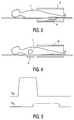
- FIG. 3 shows the magnet system of another embodiment of an MR device according to the invention.
- a first magnet is formed by a surface coil 11, which generates a strong but also very inhomogeneous magnetic field perpendicular to the longitudinal direction of the patient 7 in its immediate vicinity.
- a second magnet 12 generates a very homogeneous stationary magnetic field B 02 running in the longitudinal direction of the patient 7, which is, however, considerably weaker than the first stationary magnetic field B 01 .
- 5 shows the time course of the two magnetic fields.
- the nuclear magnetization increased by the first stationary magnetic field is initially retained after this magnetic field is switched off and is tilted in its direction by the previously switched on second stationary magnetic field.
- an MR experiment can be carried out in this phase, the improvement in the signal / noise ratio being exploited by the (still) increased nuclear magnetization.
- FIG. 4 shows another embodiment in which the two magnet systems 21 and 22 are spatially offset from one another.
- the magnet system 21 generates a strong, inhomogeneous magnetic field B 01 (in the x or y direction) in the region of the heart of the patient 7, as a result of which the nuclear magnetization in the blood flowing through the heart chambers is increased.
- This blood - and the increased nuclear magnetization - flow towards the patient's legs, where the second magnet system is located, which aligns this nuclear magnetization in the z direction.
- the distribution of the nuclear magnetization in the region of the second magnet system can then be determined using a conventional MR experiment.
- the signal / noise ratio of the MR signals received is essentially determined by the stationary magnetic field B 01 .
- the MR image derived from the received MR signals represents the patient's vascular system.
- the image contrasts in this image can be increased if the MR image that results if the same sequence - but is subtracted from this MR image is carried out without switching on the stationary magnetic field B 01 -.
Landscapes
- Physics & Mathematics (AREA)
- Electromagnetism (AREA)
- Condensed Matter Physics & Semiconductors (AREA)
- General Physics & Mathematics (AREA)
- Magnetic Resonance Imaging Apparatus (AREA)
Abstract
Description
- Erzeugung einer erhöhten Kernmagnetisierung in einem Untersuchungsbereich unter dem Einfluss eines ersten stationären Magnetfeldes,
- Einwirken eines zweiten stationären Magnetfeldes auf die zuvor durch das erste Magnetfeld beeinflussten Kerne und
- Durchführung mindestens eines MR-Experiments, nachdem das erste stationäre Magnetfeld nicht mehr auf die Kerne einwirkt, jedoch bevor die durch dieses Magnetfeld beeinflusste Kernmagnetisierung abgeklungen ist, wobei das MR-Experiment die Anregung der Kernmagnetisierung durch ein MR-Hochfrequenzmagnetfeld unter dem Einfluss des zweiten stationären Magnetfeldes umfasst.
- Fig. 1
- Ein schematisches Blockschaltbild eines MR-Gerätes zur Durchführung von MR-Untersuchungen mit Hilfe des Overhauser-Effekts,
- Fig. 2
- den zeitlichen Verlauf verschiedener Magnetfelder bzw. Signale bei diesem Verfahren,
- Fig. 3
- eine zweite Ausführungsform eines erfindungsgemäßen MR-Gerätes,
- Fig. 4
- eine dritte Ausführungsform eines MR-Gerätes und
- Fig. 5
- den zeitlichen Verlauf der stationären Magnetfelder bei diesen Geräten.
Claims (11)
- MR-Verfahren mir den Schrittendadurch gekennzeichnet,- Erzeugung einer erhöhten Kernmagnetisierung in einem Untersuchungsbereich unter dem Einfluss eines ersten stationären Magnetfeldes,- Einwirken eines zweiten stationären Magnetfeldes auf die zuvor durch das erste Magnetfeld beeinflussten Kerne und- Durchführung mindestens eines MR-Experimentes, nachdem das erste stationäre Magnetfeld nicht mehr auf die Kerne einwirkt, jedoch bevor die durch dieses Magnetfeld beeinflusste Kernmagnetisierung abgeklungen ist, wobei das MR-Experiment die Anregung der Kernmagnetisierung durch ein MR-Hochfrequenzmagnetfeld unter dem Einfluss des zweiten stationären Magnetfeldes umfasst,
dass die Richtungen des ersten und des zweite stationären Magnetfeldes einen von 0° verschiedenen, vorzugsweise 90° betragenden Winkel miteinander einschließen und dass sich die beiden stationären Magnetfelder zeitlich überlappen. - MR-Verfahren nach Anspruch 1.
dadurch gekennzeichnet,
dass die Erzeugung der erhöhten Kernmagnetisierung die Anregung der Elektronenspinresonanz eines im Untersuchungsobjekt befindlichen, ungepaarte Elektronen enthaltenden Kontrastmittels unter dem Einfluss des ersten stationären Magnetfeldes durch ein ESR-Hochfrequenzmagnetfeld umfasst und dass die Richtungen des ESR-Hochfrequenzmagnetfeldes und des MR-Hochfrequenz-Magnetfeldes einen Winkel von zumindest annähernd 90° miteinander einschließen. - MR-Verfahren nach Anspruch 2, ,
dadurch gekennzeichnet,
dass das erste stationäre Magnetfeld schwächer ist als das zweite stationäre Magnetfeld. - MR-Verfahren nach Anspruch 1,
dadurch gekennzeichnet,
dass das erste stationäre Magnetfeld impulsartig ein- und ausgeschaltet wird und stärker ist als das zweite stationäre Magnetfeld, und dass das zweite stationäre Magnetfeld eine höhere Homogenität aufweist als das erste. - MR-Verfahren nach Anspruch 1 zur Untersuchung eines Patienten,
dadurch gekennzeichnet,
dass das erste stationäre Magnetfeld auf einen ersten Abschnitt und das zweite stationäre Magnetfeld auf einen zweiten Abschnitt des Patienten einwirkt, wobei das Blut vom ersten zum zweiten Abschnitt fließt. - Anordnung zur Durchführung des Verfahrens nach Anspruch 2, mit einem ersten Magneten zur Erzeugung eines ersten stationären Magnetfeldes, einer ESR-Hochfrequenzspulenanordung zur Erzeugung eines zum ersten stationären Magnetfeld zumindest annähernd senkrecht verlaufenden ESR-Hochfrequenzmagnetfeldes, und mit einer MR-Hochfrequenzspulenanordung zur Erzeugung und/oder zum Empfang eines MR-Hochfrequenzmagnetfeldes.
dadurch gekennzeichnet,
dass ein zweiter Magnet zur Erzeugung eines zweiten stationären Magnetfeldes vorgesehen ist, dessen Richtung mit der Richtung des ersten stationären Magnetfeldes einen von 0° verschiedenen, vorzugsweise 90° betragenden, Winkel bildet und dass die Richtung des MR-Hochfrequenzmagnetfeldes zumindest annähernd senkrecht zur Richtung des zweiten stationären Magnetfeldes und zur Richtung des ESR-Hochfrequenzmagnetfeldes verläuft. - Anordnung nach Anspruch 6,
dadurch gekennzeichnet,
dass die MR-Hochfrequenzspulenanordung (5) und die ESR-Hochfrequenzspulenanordung (6) einander umschließen und zueinander koaxial verlaufen. - Anordnung nach Anspruch 7,
dadurch gekennzeichnet,
dass die MR-Hochfrequenzspulenanordung eine Solenoid-Spule umfasst. - Anordnung nach Anspruch 7,
dadurch gekennzeichnet,
dass die ESR-Hochfrequenzspulenanordung eine Quadraturspule vom Birdcage-Typ ist. - Anordnung nach Anspruch 7,
dadurch gekennzeichnet,
dass die ESR-Hochfrequenzspulenanordung ein TEM-Resonator ist. - Anordnung nach Anspruch 7,
dadurch gekennzeichnet,
dass die ESR-Hochfrequenzspulenanordung ein Array von einen zylinderförmigen Raum umschließenden Oberflächenspulen umfasst.
Applications Claiming Priority (2)
| Application Number | Priority Date | Filing Date | Title |
|---|---|---|---|
| DE19911043A DE19911043A1 (de) | 1999-03-12 | 1999-03-12 | MR-Verfahren |
| DE19911043 | 1999-03-12 |
Publications (2)
| Publication Number | Publication Date |
|---|---|
| EP1035416A2 true EP1035416A2 (de) | 2000-09-13 |
| EP1035416A3 EP1035416A3 (de) | 2002-06-19 |
Family
ID=7900731
Family Applications (1)
| Application Number | Title | Priority Date | Filing Date |
|---|---|---|---|
| EP00200801A Withdrawn EP1035416A3 (de) | 1999-03-12 | 2000-03-03 | MR-Verfahren |
Country Status (4)
| Country | Link |
|---|---|
| US (1) | US6466812B1 (de) |
| EP (1) | EP1035416A3 (de) |
| JP (1) | JP2000262491A (de) |
| DE (1) | DE19911043A1 (de) |
Families Citing this family (4)
| Publication number | Priority date | Publication date | Assignee | Title |
|---|---|---|---|---|
| DE10009166A1 (de) * | 2000-02-26 | 2001-08-30 | Philips Corp Intellectual Pty | Verfahren zur Lokalisierung von Objekten in der interventionellen Radiologie |
| WO2005088330A1 (en) * | 2004-03-03 | 2005-09-22 | Koninklijke Philips Electronics, N.V. | Asymmetric ultra-short gradient coil for magnetic resonance imaging system |
| CN101325977A (zh) * | 2005-12-08 | 2008-12-17 | 皇家飞利浦电子股份有限公司 | 使用Overhauser增强的NMR监测体内药物释放的系统和方法 |
| DE102020200013A1 (de) * | 2020-01-03 | 2021-07-08 | Siemens Healthcare Gmbh | Magnetresonanzeinrichtung und Verfahren zum Betrieb einer Magnetresonanzeinrichtung, Computerprogramm und elektronisch lesbarer Datenträger |
Family Cites Families (15)
| Publication number | Priority date | Publication date | Assignee | Title |
|---|---|---|---|---|
| US4719425A (en) * | 1986-04-15 | 1988-01-12 | Scientific Innovations, Inc. | NMR imaging method and apparatus |
| GB8819753D0 (en) * | 1988-08-19 | 1988-09-21 | Nycomed As | Apparatus |
| FR2621392A1 (fr) * | 1988-09-30 | 1989-04-07 | Gen Electric Cgr | Machine de rmn a bas champ et a polarisation dynamique |
| FI85193C (fi) * | 1989-11-27 | 1992-03-10 | Instrumentarium Oy | Undersoekningsfoerfarande och - anordning. |
| GB9024528D0 (en) * | 1990-11-12 | 1991-01-02 | Instrumentarium Corp | Improvements in and relating to magnetic resonance imaging |
| US5564421A (en) * | 1991-04-04 | 1996-10-15 | Instrumentarium Corporation | VHF applicator for magnetic resonance imaging |
| FI91448C (fi) * | 1991-11-22 | 1994-06-27 | Picker Nordstar Oy | Magneettikuvauslaite ja -menetelmä |
| GB9518442D0 (en) * | 1995-09-08 | 1995-11-08 | Nycomed Imaging As | Method |
| GB2276945B (en) * | 1993-04-08 | 1997-02-26 | Oxford Magnet Tech | Improvements in or relating to MRI magnets |
| US5617859A (en) * | 1995-10-02 | 1997-04-08 | General Electric Company | Apparatus and methods for magnetic resonance (MR) imaging of cavities using fluids polarized at low temperatures |
| DE19619471C1 (de) * | 1996-05-14 | 1997-10-16 | Siemens Ag | Kernspintomographiegerät mit Vorpolarisation |
| GB9614139D0 (en) * | 1996-07-05 | 1996-09-04 | Nycomed Imaging As | Method |
| US5835995A (en) * | 1996-10-28 | 1998-11-10 | Macovski; Albert | Localized pulsed superconductive MRI system |
| CN1269015A (zh) * | 1997-06-19 | 2000-10-04 | 耐克麦德英梅金公司 | 使用体外极化磁共振成像剂的奥氏磁共振成像方法 |
| DE69830105T2 (de) * | 1997-07-29 | 2006-02-02 | Philips Medical Systems (Cleveland), Inc., Cleveland | Bewegliche Vorpolarisierungseinheit für ein Gerät zur Bilderzeugung mittels magnetischer Resonanz |
-
1999
- 1999-03-12 DE DE19911043A patent/DE19911043A1/de not_active Withdrawn
-
2000
- 2000-03-02 US US09/517,715 patent/US6466812B1/en not_active Expired - Fee Related
- 2000-03-03 EP EP00200801A patent/EP1035416A3/de not_active Withdrawn
- 2000-03-10 JP JP2000067342A patent/JP2000262491A/ja active Pending
Also Published As
| Publication number | Publication date |
|---|---|
| US6466812B1 (en) | 2002-10-15 |
| JP2000262491A (ja) | 2000-09-26 |
| DE19911043A1 (de) | 2000-09-14 |
| EP1035416A3 (de) | 2002-06-19 |
Similar Documents
| Publication | Publication Date | Title |
|---|---|---|
| DE3850559T2 (de) | Vorrichtung zum schnellen Ausserbetriebsetzen einer Feldspule der magnetischen Kernresonanz. | |
| DE10250922B4 (de) | Verfahren zur Ermittlung des ADC-Koeffizienten in der Diffusionsgewichteten Magnetresonanz-Bildgebung bei Verwendung von Steady-State-Sequenzen | |
| EP0071896B1 (de) | Hochfrequenz-Spulensystem für ein Kernresonanz-Abbildungsgerät | |
| DE60035829T2 (de) | RF-Körperspule für ein offenes System zur Bilderzeugung mittels magnetischer Resonanz | |
| EP0642031B1 (de) | MR-Abbildungsverfahren und Anordnung zur Durchführung des Verfahrens | |
| DE3854661T2 (de) | Verfahren zur Darstellung der Verteilung von paramagnetischen Molekülen in einem Lösungsmittel. | |
| DE69925193T2 (de) | Mehrfrequenz-Magnetresonanzbildgebung | |
| EP0789251B1 (de) | MR-Verfahren zur Bestimmung der Magnetfeldinhomogenität im Untersuchungsbereich und MR-Gerät zur Durchführung des Verfahrens | |
| EP0412602B1 (de) | Kernresonanz-Spektroskopieverfahren und Anordnung zur Durchführung des Verfahrens | |
| EP0404248A2 (de) | Kernresonanzabbildungsverfahren | |
| EP0259935B1 (de) | Kernspintomographiverfahren und Kernspintomograph zur Durchführung des Verfahrens | |
| DE3739856A1 (de) | Kernresonanz-spektroskopieverfahren | |
| EP0357100A2 (de) | Kernspintomographieverfahren und Kernspintomograph zur Durchführung des Verfahrens | |
| DE69332560T2 (de) | Verfahren zur bildgebung der verteilung von paramagnetischem material in loesung | |
| EP1035416A2 (de) | MR-Verfahren | |
| EP0430322A2 (de) | Kernspintomographieverfahren und Kernspintomograph zur Durchführung des Verfahrens | |
| EP1107015B1 (de) | MR-Verfahren zur Erzeugung von Navigatorimpulsen | |
| EP0369538B1 (de) | Kernspintomographieverfahren zur Bestimmung der Kernmagnetisierung in einer Anzahl paralleler Schichten | |
| DE3604281A1 (de) | Verfahren zur bestimmung der kernmagnetisierungsverteilung in einer schicht eines untersuchungsbereiches und kernspintomograph zur durchfuehrung des verfahrens | |
| DE3837317A1 (de) | Kernresonanzspektroskopieverfahren und anordnung zur durchfuehrung des verfahrens | |
| DE4203036A1 (de) | Verfahren zur erzeugung eines seitenbandfreien nmr-spektrums | |
| DE4018683A1 (de) | Schichtprofiloptimierung fuer ein mit einer gradientenechosequenz betriebenes kernspin-tomographiegeraet | |
| DE10218515B4 (de) | Verfahren zur Verbesserung des Gefäß-Gewebe-Kontrastes in der Time-of-flight Angiographie einer Magnetresonanz-Tomographie-Messung | |
| DE3410215A1 (de) | Hochfrequenz-antenneneinrichtung in einer kernspintomographie-apparatur und verfahren zu ihrem betrieb | |
| EP0478030A1 (de) | Verfahren für die zweidimensionale Kernresonanzspektroskopie |
Legal Events
| Date | Code | Title | Description |
|---|---|---|---|
| PUAI | Public reference made under article 153(3) epc to a published international application that has entered the european phase |
Free format text: ORIGINAL CODE: 0009012 |
|
| AK | Designated contracting states |
Kind code of ref document: A2 Designated state(s): AT BE CH CY DE DK ES FI FR GB GR IE IT LI LU MC NL PT SE |
|
| AX | Request for extension of the european patent |
Free format text: AL;LT;LV;MK;RO;SI |
|
| PUAL | Search report despatched |
Free format text: ORIGINAL CODE: 0009013 |
|
| AK | Designated contracting states |
Kind code of ref document: A3 Designated state(s): AT BE CH CY DE DK ES FI FR GB GR IE IT LI LU MC NL PT SE |
|
| AX | Request for extension of the european patent |
Free format text: AL;LT;LV;MK;RO;SI |
|
| RAP1 | Party data changed (applicant data changed or rights of an application transferred) |
Owner name: PHILIPS CORPORATE INTELLECTUAL PROPERTY GMBH Owner name: KONINKLIJKE PHILIPS ELECTRONICS N.V. |
|
| 17P | Request for examination filed |
Effective date: 20021219 |
|
| AKX | Designation fees paid |
Designated state(s): DE FR GB NL |
|
| RAP1 | Party data changed (applicant data changed or rights of an application transferred) |
Owner name: PHILIPS INTELLECTUAL PROPERTY & STANDARDS GMBH Owner name: KONINKLIJKE PHILIPS ELECTRONICS N.V. |
|
| STAA | Information on the status of an ep patent application or granted ep patent |
Free format text: STATUS: THE APPLICATION HAS BEEN WITHDRAWN |
|
| 18W | Application withdrawn |
Effective date: 20030613 |