EP1035303A2 - Internal combustion engine variable valve characteristic control apparatus and three-dimensional cam - Google Patents
Internal combustion engine variable valve characteristic control apparatus and three-dimensional cam Download PDFInfo
- Publication number
- EP1035303A2 EP1035303A2 EP00105021A EP00105021A EP1035303A2 EP 1035303 A2 EP1035303 A2 EP 1035303A2 EP 00105021 A EP00105021 A EP 00105021A EP 00105021 A EP00105021 A EP 00105021A EP 1035303 A2 EP1035303 A2 EP 1035303A2
- Authority
- EP
- European Patent Office
- Prior art keywords
- lift
- cam
- peak
- patterns
- valve
- Prior art date
- Legal status (The legal status is an assumption and is not a legal conclusion. Google has not performed a legal analysis and makes no representation as to the accuracy of the status listed.)
- Withdrawn
Links
- 238000002485 combustion reaction Methods 0.000 title claims abstract description 46
- 230000008859 change Effects 0.000 abstract description 10
- 239000000446 fuel Substances 0.000 abstract description 6
- 230000006872 improvement Effects 0.000 abstract description 6
- 239000012530 fluid Substances 0.000 description 18
- 238000010276 construction Methods 0.000 description 9
- 230000003111 delayed effect Effects 0.000 description 7
- 230000006835 compression Effects 0.000 description 6
- 238000007906 compression Methods 0.000 description 6
- 230000002093 peripheral effect Effects 0.000 description 6
- 230000007423 decrease Effects 0.000 description 5
- 230000009467 reduction Effects 0.000 description 5
- 238000010586 diagram Methods 0.000 description 3
- 230000002452 interceptive effect Effects 0.000 description 3
- 230000001934 delay Effects 0.000 description 2
- 238000001514 detection method Methods 0.000 description 2
- 101100480474 Rattus norvegicus Taar7b gene Proteins 0.000 description 1
- 101100480484 Rattus norvegicus Taar8a gene Proteins 0.000 description 1
- 101100480488 Rattus norvegicus Taar8c gene Proteins 0.000 description 1
- 101150006306 Rhoq gene Proteins 0.000 description 1
- 230000015572 biosynthetic process Effects 0.000 description 1
- 239000003054 catalyst Substances 0.000 description 1
- 239000000498 cooling water Substances 0.000 description 1
- 230000001419 dependent effect Effects 0.000 description 1
- 230000000694 effects Effects 0.000 description 1
- 230000006870 function Effects 0.000 description 1
- 230000007246 mechanism Effects 0.000 description 1
- 238000005086 pumping Methods 0.000 description 1
- 230000000717 retained effect Effects 0.000 description 1
- XLYOFNOQVPJJNP-UHFFFAOYSA-N water Substances O XLYOFNOQVPJJNP-UHFFFAOYSA-N 0.000 description 1
Images










Classifications
-
- F—MECHANICAL ENGINEERING; LIGHTING; HEATING; WEAPONS; BLASTING
- F01—MACHINES OR ENGINES IN GENERAL; ENGINE PLANTS IN GENERAL; STEAM ENGINES
- F01L—CYCLICALLY OPERATING VALVES FOR MACHINES OR ENGINES
- F01L13/00—Modifications of valve-gear to facilitate reversing, braking, starting, changing compression ratio, or other specific operations
- F01L13/0015—Modifications of valve-gear to facilitate reversing, braking, starting, changing compression ratio, or other specific operations for optimising engine performances by modifying valve lift according to various working parameters, e.g. rotational speed, load, torque
- F01L13/0036—Modifications of valve-gear to facilitate reversing, braking, starting, changing compression ratio, or other specific operations for optimising engine performances by modifying valve lift according to various working parameters, e.g. rotational speed, load, torque the valves being driven by two or more cams with different shape, size or timing or a single cam profiled in axial and radial direction
- F01L13/0042—Modifications of valve-gear to facilitate reversing, braking, starting, changing compression ratio, or other specific operations for optimising engine performances by modifying valve lift according to various working parameters, e.g. rotational speed, load, torque the valves being driven by two or more cams with different shape, size or timing or a single cam profiled in axial and radial direction with cams being profiled in axial and radial direction
-
- F—MECHANICAL ENGINEERING; LIGHTING; HEATING; WEAPONS; BLASTING
- F01—MACHINES OR ENGINES IN GENERAL; ENGINE PLANTS IN GENERAL; STEAM ENGINES
- F01L—CYCLICALLY OPERATING VALVES FOR MACHINES OR ENGINES
- F01L1/00—Valve-gear or valve arrangements, e.g. lift-valve gear
- F01L1/02—Valve drive
- F01L1/04—Valve drive by means of cams, camshafts, cam discs, eccentrics or the like
- F01L1/08—Shape of cams
-
- F—MECHANICAL ENGINEERING; LIGHTING; HEATING; WEAPONS; BLASTING
- F01—MACHINES OR ENGINES IN GENERAL; ENGINE PLANTS IN GENERAL; STEAM ENGINES
- F01L—CYCLICALLY OPERATING VALVES FOR MACHINES OR ENGINES
- F01L1/00—Valve-gear or valve arrangements, e.g. lift-valve gear
- F01L1/34—Valve-gear or valve arrangements, e.g. lift-valve gear characterised by the provision of means for changing the timing of the valves without changing the duration of opening and without affecting the magnitude of the valve lift
-
- F—MECHANICAL ENGINEERING; LIGHTING; HEATING; WEAPONS; BLASTING
- F01—MACHINES OR ENGINES IN GENERAL; ENGINE PLANTS IN GENERAL; STEAM ENGINES
- F01L—CYCLICALLY OPERATING VALVES FOR MACHINES OR ENGINES
- F01L1/00—Valve-gear or valve arrangements, e.g. lift-valve gear
- F01L1/34—Valve-gear or valve arrangements, e.g. lift-valve gear characterised by the provision of means for changing the timing of the valves without changing the duration of opening and without affecting the magnitude of the valve lift
- F01L1/344—Valve-gear or valve arrangements, e.g. lift-valve gear characterised by the provision of means for changing the timing of the valves without changing the duration of opening and without affecting the magnitude of the valve lift changing the angular relationship between crankshaft and camshaft, e.g. using helicoidal gear
Definitions
- the present invention relates to an internal combustion engine variable cam characteristic control apparatus that changes the valve characteristics of one or both of an intake valve and an exhaust valve through the use of a cam by changing the profile of the cam between two lift patterns, and a three-dimensional cam for use in the control apparatus.
- variable engine valve driver which suitably controls the engine characteristic by changing the operation angle or the amount of lift of an intake valve or an exhaust valve in accordance with the operating condition of an internal combustion engine is known (disclosed in, for example, United States Patent No. 5,870,984).
- This apparatus adopts a three-dimensional cam provided on the camshaft, and adjusts the position of the camshaft in directions of the rotating axis of the camshaft so as to continuously change the cam profile, thereby achieving a proper operation angle and a proper amount of lift.
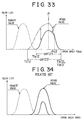
- the aforementioned three-dimensional cam has a cam profile as indicated by the graph in Fig. 34.
- the valve characteristic of the three-dimensional cam is adjusted by continuously changing the cam profile between a pattern having a small peak of lift and a pattern having a simply increased total amount of lift as indicated by solid lines in the graph of Fig. 34.
- the valve operation angle is expanded forward and rearward, so that the valve opening timing advances and the valve closing timing delays.
- the valve operation angle is reduced so that the valve opening timing delays and the valve closing timing advances.
- valve characteristic does not have sufficient flexibility to adapt to various characteristic requirements of internal combustion engines and, in some cases, fails to sufficiently contribute to a desired engine performance improvement.
- variable valve characteristic control apparatus that achieves a change in the valve characteristic in accordance with a requirement of an internal combustion engine and provide a three-dimensional cam for use in the control apparatus.
- a variable valve characteristic control apparatus of an internal combustion engine includes a cam having a cam profile that varies at least between a first lift pattern and a second lift pattern, and a controller that controls a valve characteristic of at least one of an intake valve and an exhaust valve of the internal combustion engine by adjusting a position of the cam in a direction of a rotating axis of the cam.
- the first lift pattern and the second lift pattern provide equal amounts of lift at least at a phase within a valve operation angle.
- a three-dimensional cam for use for at least one of an intake valve and an exhaust valve of an internal combustion engine has a cam profile that continuously varies between a first lift pattern and a second lift pattern that provides an amount of lift equal to an amount of lift provided by the first lift pattern at least at a phase within a valve operation angle.
- the three-dimensional cam achieves, for at least one of the intake valve and the exhaust valve, different amounts of lift at a portion of a valve operation angle and equal amounts of lift at another portion of the valve operation angle. That is, within the valve operation angle, there exists a phase where the amount of lift remains unchanged despite a change of the operating cam profile. Therefore, it becomes possible to select a phase where various cam profiles provide equal amounts of lift and set different amounts of lift occurring at the other phases in accordance with the characteristics of the internal combustion engine.
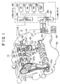
- FIG. 1 is a schematic illustration of the construction of an internal combustion engine 11 in which a variable valve characteristic control apparatus according to the invention is incorporated.
- Fig. 1 also shows a block diagram of an electronic control unit (hereinafter, referred to as "ECU") 80 provided as a control system.
- ECU electronice control unit
- the engine 11 is an in-line four-cylinder gasoline engine for a vehicle.
- the engine 11 has a cylinder block 13 provided with reciprocating pistons 12, an oil pan 13a provided below the cylinder block 13, and a cylinder head 14 provided above the cylinder block 13.
- the crankshaft 15 is connected to the pistons 12 via connecting rods 16. Reciprocating movements of the pistons 12 are converted into rotation of the crankshaft 15 by the connecting rods 16.
- a combustion chamber 17 is formed above each piston 12.
- the combustion chambers 17 are connected to an intake passage 18 and an exhaust passage 19. Communication between the intake passage 18 and the combustion chambers 17 is established and blocked by corresponding intake valves 20. Communication between the exhaust passage 19 and the combustion chambers 17 is established and blocked by corresponding exhaust valves 21.
- An intake-side camshaft 22 and an exhaust-side camshaft 23 extend in parallel in the cylinder head 14.
- the intake-side camshaft 22 is supported by the cylinder head 14 so that the intake-side camshaft 22 is rotatable and movable in the directions of an axis thereof
- the exhaust-side camshaft 23 is supported by the cylinder head 14 so that the exhaust-side camshaft 23 is rotatable but is prevented from moving in the axial directions.
- An end portion of the intake-side camshaft 22 is provided with a variable valve characteristic control device 24 having a timing sprocket 24a.
- An end portion of the exhaust-side camshaft 23 is provided with a timing sprocket 25.
- the timing sprocket 25 and the timing sprocket 24a of the variable valve characteristic control device 24 are connected by a timing chain 26 to a sprocket 15a fixed to the crankshaft 15. Rotation of the crankshaft 15, that is, rotation of the output shaft, is transmitted to the timing sprockets 24a, 25 by the sprocket 15a and the timing chain 26, so that the intake-side camshaft 22 and the exhaust-side camshaft 23 rotate synchronously with rotation of the crankshaft 15.
- variable valve characteristic control device 24 operates on the intake-side camshaft 22 to adjust the position of the intake-side camshaft 22 in the directions of the rotating axis of the intake-side camshaft 22.
- the intake-side camshaft 22 is provided with intake cams 27 each of which contacts a corresponding valve lifter 20a provided on an upper end of each intake valve 20.
- the exhaust-side camshaft 23 is provided with exhaust cams 28 each of which contacts a corresponding valve lifter 21a provided on an upper end of each exhaust valve 21.
- each exhaust cam 28 is consistent along the rotating axis of the exhaust-side camshaft 23.
- the cam profile of each intake cam 27 on a cam surface 27a continuously changes along the rotating axis of the intake-side camshaft 22 (indicated by an arrow S). That is, the intake cams 27 are three-dimensional cams.
- the cam profile of the intake cams 27 will be described in detail below.
- variable valve characteristic control device 24 for adjusting the valve characteristic of the intake cams 27 by shifting the intake-side camshaft 22 along the rotating axis of the intake-side camshaft 22 will next be described in detail with reference to Fig. 3.
- the timing sprocket 24a of the variable valve characteristic control device 24 is substantially formed by a hollow cylindrical portion 51 through which the intake-side camshaft 22 extends, a disc portion 52 extending from an outer peripheral face of the cylindrical portion 51, and a plurality of external teeth 53 formed in an outer peripheral face of the disc portion 52.
- the cylindrical portion 51 of the timing sprocket 24a is rotatably supported by a journal bearing 14a and a camshaft bearing cap 14b of the cylinder head 14.
- the intake-side camshaft 22 extends through the cylindrical portion 51 in such a manner that the intake-side camshaft 22 is movable in the directions F/R along the axis of the intake-side camshaft 22.
- a cover 54 is fixed to the timing sprocket 24a by bolts 55 so as to cover an end portion of the intake-side camshaft 22.
- a plurality of internal teeth 57 are arranged in circumferential directions in an inner peripheral face of the cover 54 at a site thereof corresponding to the end portion of the intake-side camshaft 22. Each of the internal teeth 57 linearly extends in the directions of the rotating axis of the intake-side camshaft 22.
- a cylindrically shaped ring gear 62 is fixed to the distal end of the intake-side camshaft 22 by a hollow bolt 58 and a pin 59.
- An outer peripheral face of the ring gear 62 is provided with spur teeth 63 meshed with the internal teeth 57 of the cover 54.
- Each of the spur teeth 63 linearly extends along the rotating axis of the intake-side camshaft 22. Therefore, the ring gear 62 is movable together with the intake-side camshaft 22 in the directions F/R along the rotating axis of the intake-side camshaft 22.
- variable valve characteristic control device 24 constructed as described above, when rotation of the crankshaft 15 produced by operation of the engine 11 is transmitted to the timing sprocket 24a by the timing chain 26, the intake-side camshaft 22 is rotated via the variable valve characteristic control device 24. As the intake-side camshaft 22 rotates, the intake valves 20 are opened and closed.
- variable valve characteristic control device 24 for hydraulically controlling the movement of the ring gear 62.
- the intake-side camshaft 22 has therein a second lift pattern control fluid passage 67 and a first lift pattern control fluid passage 68 connected to the second lift pattern-side hydraulic chamber 65 and the first lift pattern-side hydraulic chamber 66, respectively.
- the second lift pattern control fluid passage 67 connects to the second lift pattern-side hydraulic chamber 65 through the hollow bolt 58, and also connects to an oil control valve 70 through an interior of the camshaft bearing cap 14b and an interior of the cylinder head 14.
- the first lift pattern control fluid passage 68 connects to the first lift pattern-side hydraulic chamber 66 through a fluid passage 72 extending through the cylindrical portion 51 of the timing sprocket 24a, and also connects to the oil control valve 70 through an interior of the camshaft bearing cap 14b and an interior of the cylinder head 14.
- a supply passage 74 and a discharge passage 76 are connected in communication to the oil control valve 70.
- the supply passage 74 is connected to the oil pan 13a via an oil pump 13b.
- the discharge passage 76 is directly connected to the oil pan 13a.
- the oil control valve 70 has an electromagnetic solenoid 70a.
- operating fluid is supplied from the oil pan 13a toward the first lift pattern-side hydraulic chamber 66 of the variable valve characteristic control device 24 via the oil control valve 70 and the first lift pattern control fluid passage 68 (as indicated by an arrow in the first lift pattern control fluid passage 68 in Fig. 3), in accordance with state of communication of ports provided inside the oil control valve 70.
- Fluid is returned from the second lift pattern-side hydraulic chamber 65 of the variable valve characteristic control device 24 toward the oil pan 13a via the second lift pattern control fluid passage 67 (as indicated by an arrow in the second lift pattern control fluid passage 67 in Fig. 3) and then via the oil control valve 70 and the discharge passage 76.
- each cam follower 20b on the corresponding cam surface 27a becomes adjacent to an end face 27c of each intake cam 27 facing in the direction R (hereinafter, referred to as a rearward end face).
- operating fluid is supplied from the oil pan 13a toward the second lift pattern-side hydraulic chamber 65 of the variable valve characteristic control device 24 via the supply passage 74, the oil control valve 70 and the second lift pattern control fluid passage 67, in accordance with the condition of communication of the ports provided in the oil control valve 70, in a manner opposite to the above-described manner Furthermore, operating fluid is returned from the first lift pattern-side hydraulic chamber 66 of the variable valve characteristic control device 24 to the oil pan 13a via the first lift pattern control fluid passage 68, the oil control valve 70 and the discharge passage 76.
- An electronic control unit (ECU) 80 that controls the oil control valve 70 as described above is formed as a logical operation circuit having a CPU 82, a ROM 83, a RAM 84, a backup RAM 85, and the like, as shown in Fig. 1.
- the ROM 83 is a memory storing various control programs, maps that are referred to when such control programs are executed, and the like.
- the CPU 82 executes necessary operations based on the various control programs stored in the ROM 83.
- the RAM 84 is a memory for temporarily storing results of the operations of the CPU 82, data inputted from various sensors, and the like.
- the backup RAM 85 is a non-volatile memory for storing data that needs to be retained even after the engine 11 is stopped.
- the CPU 82, the ROM 83, the RAM 84 and the backup RAM 85 are interconnected by a bus 86, and are connected to an external input circuit 87 and an external output circuit 88.
- the external input circuit 87 is connected to a crank-side electromagnetic pickup 90 for detecting engine revolution speed, an intake cam-side electromagnetic pickup 92 for detecting the cam angle of the intake cams 27 and the amount of movement of the intake-side camshaft 22 in the directions of the rotating axis thereof, a water temperature sensor 94 for detecting the temperature of cooling water of the engine 11, a vehicle speed sensor 96, and the like.
- the external output circuit 88 is connected to the oil control valve 70.
- This embodiment performs the valve characteristic control of the intake valves 20 by using the ECU 80 constructed as described above. That is, the ECU 80 detects operational conditions of the engine 11 based on detection signals from the various sensors. In order to achieve an appropriate operational condition of the engine 11 in accordance with the result of detection, the ECU 80 controls and drives the oil control valve 70 to adjust the lift pattern of the intake valves 20. For the lift pattern adjustment, the ECU 80 determines the position of the intake-side camshaft 22 in a direction of the rotating axis of the intake-side camshaft 22. Then, the ECU 80 executes feedback control of the variable valve characteristic control device 24 by using the oil control valve 70 so as to realize a target lift pattern of the intake valves 20.
- a nose 27b has a height that is consistent along the rotating axis of the intake cam 27.
- a cam profile at a rearward end face 27c is substantially symmetric about a line of the height of the nose 27b, that is, a valve opening-side portion and a valve closing-side portion of the cam profile are substantially symmetric.
- a cam profile at a forward end face 27d is not symmetric.
- the valve closing-side portion of the cam profile at the forward end face 27d is substantially the same as the valve closing-side portion of the cam profile at the rearward end face 27c, whereas the valve opening-side portion of the cam profile at the forward end face 27d forms a higher lift pattern (indicated by a one-dot chain line in Fig. 4) than the valve opening-side portion of the cam profile at the rearward end face 27c.
- a circle of a simple broken line indicates the cam height of zero lift (The zero-lift cam height will be indicated also by a broken line circuit in the illustrations of other embodiments.). Therefore, as indicated in Fig.
- the intake valves 20 can provide a first lift pattern determined by the rearward end face 27c-side cam profile (indicated by a solid line) and a second lift pattern determined by the forward end face 27d-side cam profile (indicated by a one-dot chain line).
- phase a crank angle phase of peak P, that is, a maximum lift
- the second lift pattern is higher than the first lift pattern, thereby providing a difference in amount of lift.
- the opening timing Tc1 of each intake valve 20 determined by the second lift pattern is earlier than the opening timing Ta1 of the intake valve 20 determined by the first lift pattern.
- the closing timing Td1 of the intake valve 20 determined by the second lift pattern is the same as the closing timing Tb1 thereof determined by the first lift pattern. Therefore, the valve operation angle d ⁇ 12 of the second lift pattern is greater than the valve operation angle d ⁇ 11 of the first lift pattern.
- each intake cam 27 has, on the sides of the end faces 27c, 27d along the rotating axis, two cam profiles determining the two different lift patterns as described above.
- the cam profile continuously varies from one of the two cam profiles to the other cam profile. Therefore, the lift pattern of the intake valves 20 can be varied continuously between the first lift pattern indicated by the solid line in Fig. 5 and the second lift pattern indicated by the one-dot chain line in Fig. 5 through the control of the oil control valve 70.
- the opening timing of the intake valves 20 is changed while the closing timing thereof is maintained. Although the valve opening timing is changed, the amount of lift of each intake valve 20 at the peak position P and the amount of lift in the delay side of the peak position P remain unchanged.
- the first embodiment realizes the two lift patterns and continuously various lift patterns therebetween for the intake valves 20 by driving the variable valve characteristic control device 24.
- the two lift patterns have a phase in which the amount of lift differs therebetween and a phase in which the amount of lift does not differ, within the valve operation angle. More specifically, within the valve operation angle, the amount of lift differs between the two lift patterns in the advance side of the peak P, but does not differ therebetween in the delay side of the peak P.
- the intake cams 27 have the above-described two lift patterns, a phase in which the amount of lift does not differ between the two lift patterns and differences in the amount of lift therebetween in the other phases can be set in accordance with the characteristics of the engine 11.
- a phase in which the amount of lift does not differ between the two lift patterns and differences in the amount of lift therebetween in the other phases can be set in accordance with the characteristics of the engine 11.
- the invention according to the first embodiment makes it possible to realize a combustion stability during idling, a reduction of the pump loss, sufficient internal EGR due to the valve overlap in accordance with the operational condition of the engine 11, and the like.
- each intake cam 27 provides variable amounts of lift only in the advance side of the phase of the peak of the amount of lift
- intake cams each of which provides variable amounts of lift only in the delay side of the phase of the peak of the amount of lift that is, it is possible to adopt intake cams that allow the closing timing to be advanced or delayed without changing the valve opening timing nor changing the amount of lift of the intake valves.
- This construction makes it possible to advance and delay the closing timing of the intake valves while maintaining a combustion stability, a pump loss, or a suitable internal EGR in accordance with the operational condition of the engine based on the proper opening timing and the main peak amount of lift of the intake valves. As a result, the compression ratio and the volume efficiency can be properly adjusted in accordance with the operational condition.
- FIG. 6 is a schematic illustration of an engine 111.
- the second embodiment differs from the first embodiment in that a variable valve characteristic control device 125 is not provided on a timing sprocket 124 of an intake-side camshaft 122, but it is provided integrally with a timing sprocket 125a on a side of an exhaust-side camshaft 123.
- the intake-side camshaft 122 is prevented from moving along a rotating axis of the intake-side camshaft 122, whereas the exhaust-side camshaft 123 is allowed to move along a rotating axis thereof
- Intake cams 127 have a cam profile that is consistent along the rotating axis.
- exhaust cams 128 are formed as three-dimensional cams whose cam profile changes along the rotating axis thereof Hence, an ECU 180 controls the variable valve characteristic control device 125 in a manner corresponding to the profile of the exhaust cams 128.
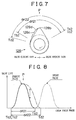
- Fig. 7 indicates the configuration (profiles) of each exhaust cam 128 in the second embodiment.
- a nose 128b is consistent along the rotating axis of the exhaust cams 128.
- a cam profile at a rearward end face 128c is substantially symmetric about a line of the height of the nose 128b. That is, a valve opening-side portion and a valve closing-side portion of the cam profile are substantially symmetric (solid line).
- a valve opening-side portion and a valve closing-side portion of a cam profile at a forward end face 128d along the rotating axis are not symmetric to each other.
- valve opening-side portion of the cam profile at the forward end face 128d is substantially the same as the valve opening-side portion of the cam profile at the rearward end face 128c, whereas the valve closing-side portion of the cam profile at the forward end face 128d forms a higher lift pattern (indicated by a one-dot chain line in Fig. 7) than the valve closing-side portion of the cam profile at the rearward end face 128c. Therefore, as indicated in Fig.
- the exhaust cams 128 can provide a first lift pattern determined by the rearward end face 128c-side cam profile (indicated by a solid line) and a second lift pattern determined by the forward end face 128d-side cam profile (indicated by a one-dot chain line).
- the second lift pattern In the delay side of the phase of a peak P, that is, a maximum amount of lift, the second lift pattern is higher than the first lift pattern, thereby providing a difference in amount of lift.
- the closing timing Td2 of each exhaust valve 121 determined by the second lift pattern is later than the closing timing Tb2 of the exhaust valve 121 determined by the first lift pattern.
- the opening timing Tc2 of each exhaust valve 121 determined by the second lift pattern is the same as the opening timing Ta2 thereof determined by the first lift pattern. Therefore, the valve operation angle d ⁇ 22 of the second lift pattern is greater than the valve operation angle d ⁇ 21 of the first lift pattern.
- each exhaust cam 128 has, on the sides of the end faces 128c, 128d in the directions F/R along the rotating axis, two cam profiles determining the two different lift patterns as described above.
- the cam profile continuously varies from one of the two cam profiles to the other cam profile. Therefore, the lift pattern of the exhaust valves 121 can be varied continuously between the first lift pattern indicated by the solid line in Fig. 8 and the second lift pattern indicated by the one-dot chain line in Fig. 8 through the control of an oil control valve 170.
- the closing timing of the exhaust valves 121 is changed while the opening timing thereof is maintained. Although the valve closing timing is changed, the amount of lift of each exhaust valve 121 at the peak position P and the amount of lift in the advance side of the peak position P remain unchanged.
- the invention according to the second embodiment is able to delay or advance the closing timing of the exhaust valves 121 without changing the amount of lift at the peak P or changing the opening timing of the exhaust valves 121.
- each exhaust cam 128 provides variable amounts of lift only in the delay side of the phase of the peak of the amount of lift
- exhaust cams in which each provides variable amounts of lift only in the advance side of the phase of the peak of the amount of lift. That is, it is possible to adopt exhaust cams that allow the opening timing to be advanced or delayed without changing the valve closing timing or the amount of lift of the exhaust valves. This makes it possible to advance and delay the opening timing of the exhaust valves while maintaining a combustion stability, a pump loss, or a suitable internal EGR in accordance with the operational condition of the engine based on the proper closing timing and the peak amount of lift of the exhaust valves. As a result, the blow-down can be varied, so that the catalyst activity can be quickly increased during an engine warm-up operation.
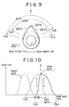
- a third embodiment of the invention will be described with reference to Fig. 9 and differs from the first embodiment only in the cam configuration (profiles) of intake cams 227.
- the height of a nose 227b is consistent along a rotating axis of the intake cam 227.
- a cam profile at a rearward end face 227c is not symmetric. More specifically, a valve closing-side portion of the cam profile at the rearward end face 227c has a higher lift pattern than the valve opening-side portion of the cam profile at the rearward end face 227c (indicated by a solid line in Fig. 9).
- a cam profile at a forward end face 227d is not symmetric either.
- a valve opening-side portion of the cam profile at the forward end face 227d has a higher lift pattern than a valve closing-side portion of the cam profile at the forward end face 227d (indicated by a one-dot chain line in Fig. 9).
- the cam profiles at the forward end face 227d and the rearward end face 227c will be compared.
- the valve opening-side portion of the forward end face 227d-side cam profile (indicated by the one-dot chain line) has a higher lift pattern than the valve-opening side portion of the rearward end face 227c-side cam profile (indicated by the solid line).
- the valve closing-side portion of the forward end face 227d-side cam profile (indicated by the one-dot chain line) has a lower lift pattern than the valve-closing side portion of the rearward end face 227c-side cam profile (indicated by the solid line).
- the intake valve opening timing Tc3 determined by the forward end face 227d-side cam profile is earlier than the intake valve opening timing Ta3 determined by the rearward end face 227c-side cam profile.
- the intake valve closing timing Td3 determined by the forward end face 227d-side cam profile is earlier than the intake valve closing timing Tb3 determined by the rearward end face 227c-side cam profile.
- Fig. 10 is a graph indicating the lift pattern achieved by each intake cam 227.
- the phase of the lift peak P and the amount of lift at the peak P do not differ between the rearward end face 227c-side lift pattern and the forward end face 227d-side lift pattern.
- the forward end face 227d-side lift pattern (indicated by a one-dot chain line) is higher than the rearward end face 227c-side lift pattern (indicated by a solid line), thereby providing a difference in amount of lift.
- the rearward end face 227c-side lift pattern (solid line) is higher than the forward end face 227d-side lift pattern (one-dot chain line), thereby providing a difference in amount of lift.
- valve operation angle d ⁇ 31 of the rearward end face 227c-side lift pattern is equal to the valve operation angle of the forward end face 227d-side lift pattern.
- each intake cam 227 has, on the sides of the end faces 227c, 227d along the rotating axis, two cam profiles determining the two different lift patterns as described above.
- the cam profile continuously varies from one of the two cam profiles to the other cam profile. Therefore, the lift pattern of the intake valves can be varied continuously between the first lift pattern indicated by a solid line in Fig. 10 and the second lift pattern indicated by a one-dot chain line in Fig. 10 through the control of an oil control valve.
- the opening timing and the closing timing of the intake cams 227 are changed in the same directions while the intake valve operation angle timing is maintained in width or extension. Although the valve opening and closing timings are changed, the position of the lift peak P and the amount of lift at the peak position P of each intake cam 227 remain unchanged.
- the invention according to the third embodiment is able to delay or advance the opening timing and the closing timing of the intake cams 227 while maintaining a suitable compression rate and a suitable volume efficiency with a proper valve operation angle width and a proper amount of lift at the peak P. Therefore, it is possible to realize a combustion stability during idling, a reduction of the pump loss, sufficient internal EGR due to the valve overlap in accordance with the operational condition of the engine, and the like.
- cam configuration may also be applied to exhaust cams.
- FIG. 11 A fourth embodiment of the invention will be described with reference to Fig. 11, which differs from the first embodiment only in the cam configuration (profiles) of intake cams 327.
- the height of a nose 327b varies along the rotating axis of the intake cam 327. That is, the height of the nose 327b at a forward end face 327d (indicated by a one-dot chain line) is greater than the height of the nose 327b at a rearward end face 327c (indicated by a solid line).
- the valve opening timing Ta4, Tc4 and the valve closing timing Tb4, Td4 remain unchanged. Since the valve and opening timings remain unchanged, the valve operation angle d ⁇ 41, d ⁇ 42 and its phase remain unchanged if the lift pattern changes.
- each intake cam 327 has, on the sides of the end faces 327c, 327d along the rotating axis, two cam profiles determining the two different lift patterns as described above.
- the cam profile continuously varies from one of the two cam profiles to the other cam profile. Therefore, the lift pattern of the intake valves can be varied continuously between the first lift pattern indicated by a solid line in Fig. 12 and the second lift pattern indicated by a one-dot chain line in Fig. 12 through the control of an oil control valve.
- the thus-realized two lift patterns of the intake valves provide different amounts of lift only in a phase around a peak P, and provide equal amounts of lift in the other phases. Therefore, in this lift pattern changing control, it is possible to change only the valve lift in the phase around the peak P while maintaining the width and the phase of the intake valve operation angle. Furthermore, the position of the lift peak P remains unchanged if the amount of lift is changed. Therefore, it becomes possible to adjust the cam friction or the volume efficiency to appropriate values in accordance with the operational condition of the engine without changing the opening and closing timings of the intake valves.
- cam configuration profiles
- exhaust cams a similar cam configuration
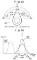
- FIG. 13 differs from the first embodiment only in the cam configuration (profiles) of intake cams 427.
- the height of a nose 427b varies along the rotating axis of the intake cam 427. That is, the height of the nose 427b at a forward end face 427d (indicated by a one-dot chain line) is greater than the height of the nose 427b, at a rearward end face 427c (indicated by a solid line).
- the lift patterns determined by the two end face-side cam profiles further differ from each other as follows.
- the opening timing Ta5 determined by the rearward end face 427c-side cam profile is advanced from the opening timing Tc5 determined by the forward end face 427d-side cam profile.
- the closing timing Tb5 determined by the rearward end face 427c-side cam profile is delayed from the closing timing Td5 determined by the forward end face 427d-side cam profile.
- the two lift patterns provide different amounts of lift in a phase in the vicinity of a peak P as indicated in Fig. 14.
- the amounts of lift in the two lift patterns become equal.
- the valve operation angle d ⁇ 51 determined by the rearward end face 427c-side lift pattern is wider than the valve operation angle d ⁇ 52 determined by the forward end face 427d-side lift pattern (indicated by a one-dot chain line).
- each intake cam 427 has, on the sides of the end faces 427c, 427d along the rotating axis, two cam profiles determining the two different lift patterns as described above.
- the cam profile continuously varies from one of the two cam profiles to the other cam profile. Therefore, the lift pattern of the intake valves can be varied continuously between the first lift pattern indicated by the solid line in Fig. 14 and the second lift pattern indicated by the one-dot chain line in Fig. 14 through the control of an oil control valve.
- an advance of the opening timing of the intake valves and a delay of the closing timing thereof are simultaneously accomplished by shifting the intake cams 427 so as to shift the cam follower contact position toward the rearward end face 427c of each intake cam 427 in accordance with the operational condition of the engine.
- the operation angle of the intake valves is expanded, so that the pumping loss of the engine can be reduced.
- the lift of the intake valves is reduced simultaneously with expansion of the valve operation angle, so that the friction of the intake cams 427 decreases. Therefore, the fuel consumption improves.
- a delay of the opening timing of the intake valves and an advance of the closing timing thereof are simultaneously accomplished by shifting the intake cams 427 so as to shift the contact position of each cam follower 20b toward the forward end face 427d of each intake cam 427.
- the operation angle of the intake valves is reduced simultaneously with an increase in the valve lift.
- FIG. 15 A sixth embodiment of the invention will be described with reference to Fig. 15, which differs from the first embodiment only in the cam configuration (profiles) of intake cams 527.
- a cam profile at a forward end face 527d indicated by a one-dot chain line in Fig. 16 has lifts of zero or less over the entire periphery, that is, no valve lift is provided. Therefore, substantially no nose 527b exists at the forward end face 527d.
- a cam profile at a rearward end face 527c indicated by a solid line provides valve lifts and a valve operation angle d ⁇ 61, and defines a nose 527b. Therefore, the height of the nose 527b increases from zero as the distance to the rearward end face 527c (solid line) decreases.
- each intake cam 527 has, on the sides of the end faces 527c, 527d along the rotating axis, the two cam profiles determining the two different lift patterns as described above.
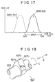
- the cam profile continuously varies from one of the two cam profiles to the other cam profile. Therefore, the lift pattern of the intake valves can be varied continuously between the first lift pattern indicated by a solid line in Fig. 17 and the second lift pattern providing no lift over the entire range through the control of an oil control valve.
- an intake cam 527 as described above and an intake cam having a certain operation angle may be employed as the two intake cams for each cylinder.
- the two intake valves for each cylinder can be caused to provide different amounts of lift so as to provide different amounts of intake, so that swirl can be produced in each cylinder.
- the intake cams have such a cam profile that the intake valves are not opened at all
- the intake valves and the exhaust cams may have such a cam profile that the intake valves and the exhaust valves remain completely closed. This construction realizes further complete cylinder operation stop. It is also possible to adopt a construction in which only the exhaust valves have such a cam profile that the exhaust valves are not opened at all, in order to realize complete cylinder operation stop.
- each intake cam 627 has a main nose 627b and a sub-nose 627e that is formed on a valve-opening side.
- the height of the sub-nose 627e is increased on the side of a forward end face 627d (indicated by a one-dot chain line).
- the height of the sub-nose 627e gradually decreases as the distance to a rearward end face 627c (indicated by a solid line) decreases.
- the profile of the other portions, including the main nose 627b, does not vary between the forward end face 627d and the rearward end face 627c. Due to the different heights of the sub-nose 627e, the valve opening timing Tc7 determined by the forward end face 627d-side cam profile is advanced from the valve opening timing Ta7 determined by the rearward end face 627c-side cam profile.
- the valve closing timings Tb7, Td7 determined by the two end cam profiles are the same.
- each intake cam 627 has, on the sides of the end faces 627c, 627d along the rotating axis, the two cam profiles determining two different lift patterns as described above.
- the cam profile continuously varies from one of the two cam profiles to the other cam profile. Therefore, the lift pattern of the intake valves can be varied continuously between the first lift pattern having a main peak MP and a relatively low sub-peak SP as indicated by a solid line in Fig. 20 and the second lift pattern having the main peak MP and a relatively high sub-peak SP as indicated by a one-dot chain line in Fig. 20, through the control of an oil control valve.
- Provision of a sub-peak SP in a lift pattern as described above forms a trough between the sub-peak SP and the main peak MP such that the intake valves are prevented from interfering with the corresponding pistons. Therefore, it becomes possible to increase the internal EGR without a danger of interference between the intake valves and the pistons.
- valve opening timing can be adjusted by adjusting the amount of lift at the sub-peak SP. Therefore, as in the first embodiment, it becomes possible to realize a combustion stability during idling, a reduction of the pump loss, sufficient internal EGR due to the valve overlap in accordance with the operational condition of the engine 11, and the like.
- cam configuration may also be applied to exhaust cams.
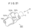
- the intake cam 727 has, on the side of a forward end face 727d indicated by a one-dot chain line in Fig. 22, a main nose 727b and a sub-nose 727e that is formed on a valve-opening side. On the side of a rearward end face 727c indicated by a solid line in Fig. 22, the sub-nose 727e substantially disappears. The profile of the other portions does not vary between the forward end face 727d and the rearward end face 727c. Due to the formation of the sub-nose 727e, the valve opening timing Tc8 determined by the forward end face 727d-side cam profile is advanced from the valve opening timing Ta8 determined by the rearward end face 727c-side cam profile. The valve closing timings Tb8, Td8 determined by the two end cam profiles are the same.
- each intake cam 727 has, on the sides of the end faces 727c, 727d along the rotating axis, the aforementioned two cam profiles determining two different lift patterns.
- the cam profile continuously varies from one of the two cam profiles to the other cam profile. Therefore, the lift pattern of the intake valves can be varied continuously between the first lift pattern having a main peak MP alone as indicated by a solid line in Fig. 23 and the second lift pattern having the main peak MP and a sub-peak SP as indicated by a one-dot chain line in Fig. 23, through the control of an oil control valve.
- Provision of a sub-peak SP in a lift pattern as described above forms a trough between the sub-peak SP and the main peak MP such that the intake valves are prevented from interfering with the corresponding pistons. Therefore, it becomes possible to increase the internal EGR without a danger of interference between the intake valves and the pistons, by changing the lift pattern from the lift pattern with no sub-peak SP to a lift pattern with a sub-peak SP as needed.
- valve opening timing can be adjusted by adjusting the amount of lift at the sub-peak SP or selecting a lift pattern with or without the sub-peak SP.
- cam configuration may also be applied to exhaust cams.
- FIG. 24 differs from the first embodiment only in the cam configuration (profiles) of intake cams 827.
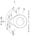
- the intake cam 827 has, on the side of a forward end face 827d indicated by a one-dot chain line in Fig. 25, a main nose 827b and a sub-nose 827e that is formed on a valve-opening side. On the side of a rearward end face 827c indicated by a solid line in Fig. 25, the sub-nose 827e substantially disappears. Although the configuration of the sub-nose 827e is substantially the same as that in the eighth embodiment, the ninth embodiment differs in that the main nose 827b is lower on the side of the forward end face 827d than on the side of the rearward end face 827c.
- valve opening timing Tc9 and the valve closing timing Td9 determined by the forward end face 827d-side cam profile are advanced from the valve opening timing Ta9 and the valve closing timing Tb9 determined by the rearward end face 827c-side cam profile, respectively.
- each intake cam 827 has, on the sides of the end faces 827c, 827d along the rotating axis, the aforementioned two cam profiles determining two different lift patterns.
- the cam profile continuously varies from one of the two cam profiles to the other cam profile. Therefore, the lift pattern of the intake valves can be varied continuously between the first lift pattern having a main peak MP alone as indicated by a solid line in Fig. 26 and the second lift pattern having the main peak MP and a sub-peak SP as indicated by a one-dot chain line in Fig. 26, through the control of an oil control valve.
- valve opening timing and the valve closing timing can be simultaneously advanced or delayed. Therefore, the opening and closing timings of the intake valves can be advanced or delayed without greatly changing the width of the valve operation angle. As a result, it becomes possible to simultaneously advance or delay the valve opening timing and the valve closing timing while maintaining a suitable compression rate and a suitable volume efficiency based on a proper valve operation angle width.
- this embodiment makes it possible to realize a combustion stability during idling, a reduction of the pump loss, sufficient internal EGR due to the valve overlap in accordance with the operational condition of the engine, and the like.
- cam configuration may also be applied to exhaust cams.
- FIG. 27 A tenth embodiment will be described with reference to Fig. 27, which differs from the first embodiment only in the cam configuration (profiles) of intake cams 927.
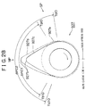
- the intake cam 927 has, on the side of a forward end face 927d indicated by a one-dot chain line in Fig. 28, a main nose 927b and a sub-nose 927e that is formed on a valve-opening side. On the side of a rearward end face 927c indicated by a solid line in Fig. 28, the sub-nose 927e substantially disappears.
- the configuration of the sub-nose 927e is substantially the same as that in the eighth embodiment, the tenth embodiment differs in that the main nose 927b is higher on the side of the forward end face 927d than on the side of the rearward end face 927c.
- the valve opening timing Tc10 determined by the forward end face 927d-side cam profile is advanced from the valve opening timing Ta10 determined by the rearward end face 927c-side cam profile, and the valve closing timing Td10 determined by the forward end face 927d-side cam profile is delayed from the valve closing timing Tb10 determined by the rearward end face 927c-side cam profile.
- each intake cam 927 has, on the sides of the end faces 927c, 927d along the rotating axis, the aforementioned two cam profiles determining two different lift patterns.
- the cam profile continuously varies from one of the two cam profiles to the other cam profile. Therefore, the lift pattern of the intake valves can be varied continuously between the first lift pattern having a main peak MP alone as indicated by a solid line in Fig. 29 and the second lift pattern having the main peak MP and a sub-peak SP as indicated by a one-dot chain line in Fig. 29, through the control of an oil control valve.
- a shift from the rearward end face 927c-side cam profile toward the forward end face 927d-side cam profile increases the amount of lift at the main peak MP and the amount of lift at the sub-peak SP, and changes the valve operation angle from a small valve operation angle d ⁇ 101 to a great valve operation angle d ⁇ 102. Therefore, large amounts of air can be introduced into the cylinders while the intake valves are prevented from interfering with the pistons. As a result, the engine output performance can be further improved.
- cam configuration may also be applied to exhaust cams.
- the height of a nose 1027b changes in the directions of a rotating axis of the intake cam 1027.
- the height of the nose 1027b is reduced on the side of a rearward end face 1027c (indicated by a solid line).
- a lift pattern on the side of the rearward end face 1027c is not symmetric. More specifically, a valve closing side portion of the rearward end face 1027c-side lift pattern is higher than a valve opening side portion of the lift pattern.
- the height of the nose 1027b is increased on the side of a forward end face 1027d (indicated by a one-dot chain line).
- a lift pattern on the side of the forward end face 1027d is not symmetric. More specifically, a valve opening side portion of the forward end face 1027d-side lift pattern is higher than a valve closing side portion of the lift pattern.
- the rearward end face 1027c-side cam profile and the forward end face 1027d-side cam profile provide equal amounts of lift at a phase ⁇ c1.
- the forward end face 1027d-side cam profile one-dot chain line
- the rearward end face 1027c-side cam profile solid line
- the rearward end face 1027c-side cam profile solid line
- the intake valve opening timing Tc11 determined by the forward end face 1027d-side cam profile is advanced from the intake valve opening timing Ta11 determined by the rearward end face 1027c-side cam profile. Furthermore, the intake valve closing timing Td11 determined by the forward end face 1027d-side cam profile is advanced from the intake valve closing timing Tb11 determined by the rearward end face 1027c-side cam profile.
- the forward end face 1027d-side cam profile and the rearward end face 1027c-side cam profile achieve maximum amounts of lift, that is, peaks P, at the same phase. However, the amount of lift achieved at the peak P by the forward end face 1027d-side cam profile is greater than the amount of lift achieved at the peak P by the rearward end face 1027c-side cam profile.
- the width of valve operation angle of the rearward end face 1027c-side cam profile and the width of valve operation angle of the forward end face 1027d-side cam profile are equal.
- each intake cam 1027 has, on the sides of the end faces 1027c, 1027d in the directions of the rotating axis, the aforementioned two cam profiles determining two different lift patterns.
- the cam profile continuously varies from one of the two cam profiles to the other cam profile. Therefore, the lift pattern of the intake valves can be varied continuously between the first lift pattern indicated by the solid line in Fig. 31 and the second lift pattern indicated by the one-dot chain line in Fig. 31, through the control of an oil control valve.
- the amount of lift of the intake valves at the peak P is adjusted and the valve opening timing and the valve closing timing are changed in the same direction while the operation angle width of the intake valves is maintained.
- the valve opening and closing timings and the amount of lift at the peak P are changed, the position (phase) of the peak P of the intake valves is not changed.
- this embodiment is able to adjust the amount of lift of the intake valves at the peak P and simultaneously advance or delay the opening timing and the closing timing of the intake valves without changing the valve operation angle width. Therefore, it is possible to adjust the amount of lift at the peak P and simultaneously advance or delay the valve opening and closing timings while maintaining a suitable compression rate and a suitable volume efficiency based on an appropriate valve operation angle width. Hence, it becomes possible to adjust the combustion characteristic of the engine in a further minute manner in accordance with the operational condition of the engine.
- FIG. 32 A twelfth embodiment of the invention will be described with reference to Fig. 32, which differs from the first embodiment only in the cam configuration (profiles) of intake cams 1127.
- the height of a nose 1127b changes along a rotating axis of the intake cam 1127.
- the height of the nose 1127b is reduced on the side of a rearward end face 1127c indicated by a solid line in Fig. 32.
- a lift pattern on the side of the rearward end face 1127c is substantially symmetric.
- the height of the nose 1127b is increased on the side of a forward end face 1127d indicated by a one-dot chain line in Fig. 32.
- a lift pattern on the side of the forward end face 1127d is formed as follows. That is, a valve opening side portion of the forward end face 1127d-side lift pattern is higher than a valve closing side portion of the lift pattern.
- the rearward end face 1127c-side cam profile and the forward end face 1127d-side cam profile provide different amounts of lift only in the advance side of a phase ⁇ c2.
- the forward end face 1127d-side cam profile (one-dot chain line) provides greater amounts of lift than the rearward end face 1127c-side cam profile (solid line).
- the intake valve opening timing Tc12 determined by the forward end face 1127d-side cam profile is advanced from the intake valve opening timing Ta12 determined by the rearward end face 1127c-side cam profile.
- the intake valve closing timing Td12 determined by the forward end face 1127d-side cam profile and the intake valve closing timing Tb12 determined by the rearward end face 1127c-side cam profile are the same.
- the forward end face 1127d-side cam profile and the rearward end face 1127c-side cam profile achieve maximum amounts of lift, that is, peaks P, at the same phase.
- the amount of lift achieved at the peak P by the forward end face 1127d-side cam profile is greater than the amount of lift achieved at the peak P by the rearward end face 1127c-side cam profile.
- the forward end face 1127d-side lift pattern and the rearward end face 1127c-side lift pattern provide different amounts of lift; more specifically, the forward end face 1127d-side lift pattern is higher than the rearward end face 1127c-side lift pattern.
- the valve operation angle d ⁇ 122 determined by the forward end face 1127d-side lift pattern is expanded on the advance side, in comparison with the valve operation angle d ⁇ 121 determined by the rearward end face 1127c-side lift pattern.
- each intake cam 1127 has, on the sides of the end faces 1127c, 1127d in the directions of the rotating axis, the aforementioned two cam profiles determining two different lift patterns.
- the cam profile continuously varies from one of the two cam profiles to the other cam profile. Therefore, the lift pattern of the intake valves can be varied continuously between the first lift pattern indicated by the solid line in Fig. 33 and the second lift pattern indicated by the one-dot chain line in Fig. 33, through the control of an oil control valve.
- this embodiment is able to simultaneously change the amount of lift at the peak P and the opening timing of the intake valves without changing the peak position nor the closing timing thereof Therefore, it is possible to adjust the amount of lift at the peak P and advance or delay the valve opening timing while maintaining a suitable compression rate and a suitable volume efficiency based on an appropriate valve closing timing. Hence, it becomes possible to adjust the combustion characteristic of the engine in a further minute manner in accordance with the operational condition of the engine.
- the foregoing embodiments of the invention employ intake (or exhaust) cams each having two different lift patterns, so that the phase at which the two lift patterns provide equal amounts of lift and the different amounts of lift provided by the two lift patterns in phases other than that phase can be set in accordance with the characteristics of the engine. Therefore, it becomes possible to achieve conformation to the characteristics of the engine and constantly realize a suitable valve characteristic in accordance with the operational condition of the engine. Therefore, improvements can be achieved in the output performance of the engine, the fuel consumption, and the combustion stability, and the like.
- variable valve characteristic control device 24 in the switching of the lift pattern through the use of the variable valve characteristic control device 24, continuously change the cam profile between the two lift patterns by shifting the three-dimensional intake (exhaust) cams in the directions of the rotating axis of the intake cams. Therefore, the valve characteristic can be controlled with high precision in accordance with the operational condition of the engine.
- the cam profile may also be changed stepwise between the two lift patterns. Furthermore, more than two lift patterns may also be used.
- the camshaft may also be relatively rotated when the camshaft is moved in a direction of the rotating axis of the camshaft.
- the camshaft normally has a cam profile that is predetermined taking into consideration the relative rotation of the camshaft.
- Variable valve characteristic control apparatuses (24, 125) realize a change in a valve characteristic in accordance with a requirement of an internal combustion engine (11) and a three-dimensional cam (27, 28) for use in the variable valve characteristic control apparatus.
- an intake valve (20) two lift patterns and continuously varying lift patterns between the two lift patterns are realized by the three-dimensional cam through the driving of the variable valve characteristic control apparatus (24, 125).
- the two lift patterns provide different amounts of lift in the delay side of a peak (P) within a valve operation angle, but provide equal amounts of lift in the delay side of the peak.
- the intake cam (27) has the two lift patterns, it is possible to select a phase where the two lift patterns provide equal amounts of lift and provide different amounts of lift in phases other than the equal-lift phase so as to accord to the characteristics of the internal combustion engine (11). Therefore, it is possible to achieve conformation to the characteristics of the engine and therefore constantly realize a suitable valve characteristic in accordance with the operational condition of the engine. Hence, improvements can be achieved in the output performance of the engine, the fuel consumption, the combustion stability and the like.
Landscapes
- Engineering & Computer Science (AREA)
- Mechanical Engineering (AREA)
- General Engineering & Computer Science (AREA)
- Valve Device For Special Equipments (AREA)
- Output Control And Ontrol Of Special Type Engine (AREA)
- Valve-Gear Or Valve Arrangements (AREA)
Abstract
Description
- The present invention relates to an internal combustion engine variable cam characteristic control apparatus that changes the valve characteristics of one or both of an intake valve and an exhaust valve through the use of a cam by changing the profile of the cam between two lift patterns, and a three-dimensional cam for use in the control apparatus.
- A variable engine valve driver which suitably controls the engine characteristic by changing the operation angle or the amount of lift of an intake valve or an exhaust valve in accordance with the operating condition of an internal combustion engine is known (disclosed in, for example, United States Patent No. 5,870,984).
- This apparatus adopts a three-dimensional cam provided on the camshaft, and adjusts the position of the camshaft in directions of the rotating axis of the camshaft so as to continuously change the cam profile, thereby achieving a proper operation angle and a proper amount of lift.
- The aforementioned three-dimensional cam has a cam profile as indicated by the graph in Fig. 34. The valve characteristic of the three-dimensional cam is adjusted by continuously changing the cam profile between a pattern having a small peak of lift and a pattern having a simply increased total amount of lift as indicated by solid lines in the graph of Fig. 34. For an increase in the valve lift (a change from a small-peak pattern to a great-peak pattern), the valve operation angle is expanded forward and rearward, so that the valve opening timing advances and the valve closing timing delays. Conversely, for a decrease in the valve lift (a change from a great-peak pattern to a small-lift pattern), the valve operation angle is reduced so that the valve opening timing delays and the valve closing timing advances.
- However, this simple manner of changing the valve characteristic does not have sufficient flexibility to adapt to various characteristic requirements of internal combustion engines and, in some cases, fails to sufficiently contribute to a desired engine performance improvement.
- Accordingly, it is an object of the invention to provide a variable valve characteristic control apparatus that achieves a change in the valve characteristic in accordance with a requirement of an internal combustion engine and provide a three-dimensional cam for use in the control apparatus.
- To achieve the aforementioned and other objects, a variable valve characteristic control apparatus of an internal combustion engine according to an aspect of the invention includes a cam having a cam profile that varies at least between a first lift pattern and a second lift pattern, and a controller that controls a valve characteristic of at least one of an intake valve and an exhaust valve of the internal combustion engine by adjusting a position of the cam in a direction of a rotating axis of the cam. The first lift pattern and the second lift pattern provide equal amounts of lift at least at a phase within a valve operation angle.
- A three-dimensional cam for use for at least one of an intake valve and an exhaust valve of an internal combustion engine has a cam profile that continuously varies between a first lift pattern and a second lift pattern that provides an amount of lift equal to an amount of lift provided by the first lift pattern at least at a phase within a valve operation angle.
- Therefore, the three-dimensional cam achieves, for at least one of the intake valve and the exhaust valve, different amounts of lift at a portion of a valve operation angle and equal amounts of lift at another portion of the valve operation angle. That is, within the valve operation angle, there exists a phase where the amount of lift remains unchanged despite a change of the operating cam profile. Therefore, it becomes possible to select a phase where various cam profiles provide equal amounts of lift and set different amounts of lift occurring at the other phases in accordance with the characteristics of the internal combustion engine.
- As a result, it becomes possible to realize a suitable valve characteristic in accordance with a requirement of an internal combustion engine. Therefore, further improvements can be achieved in the output performance of the internal combustion engine, the fuel consumption, the combustion stability, and the like.
- Although this summary does not describe all the features of the present invention, it should be understood that any combination of the features stated in the dependent claims is within the scope of the present invention.
- The foregoing and further objects, features and advantages of the present invention will become apparent from the following description of preferred embodiments with reference to the accompanying drawings, wherein like numerals are used to represent like elements and wherein:
- Fig. 1 is a schematic illustration of the construction of an engine and a control system where a variable valve characteristic control apparatus according to a first embodiment of the invention is incorporated;
- Fig. 2 is a perspective view of an intake cam according to the first embodiment;
- Fig. 3 shows a longitudinal sectional view of the variable valve characteristic control apparatus of the first embodiment and an illustration of a hydraulic system;
- Fig. 4 is an illustration of cam profiles of the intake cam of the first embodiment;
- Fig. 5 is a graph indicating lift patterns achieved by the intake cam of the first embodiment;
- Fig. 6 is a schematic illustration of the construction of an engine and a control system in which a variable valve characteristic control apparatus according to a second embodiment of the invention is incorporated;
- Fig. 7 is an illustration of cam profiles of an exhaust cam according to the second embodiment;
- Fig. 8 is a graph indicating lift patterns achieved by the exhaust cam of the second embodiment;
- Fig. 9 is an illustration of cam profiles of an intake cam according to a third embodiment of the invention;
- Fig. 10 is a graph indicating lift patterns achieved by the intake cam of the third embodiment;
- Fig. 11 is an illustration of cam profiles of an intake cam according to a fourth embodiment of the invention;
- Fig. 12 is a graph indicating lift patterns achieved by the intake cam of the fourth embodiment;
- Fig. 13 is an illustration of cam profiles of an intake cam according to a fifth embodiment of the invention;
- Fig. 14 is a graph indicating lift patterns achieved by the intake cam of the fifth embodiment;
- Fig. 15 is a perspective view of an intake cam according to a sixth embodiment of the invention;
- Fig. 16 is an illustration of cam profiles of the intake cam of the sixth embodiment;
- Fig. 17 is a graph indicating lift patterns achieve by the intake cam of the sixth embodiment;
- Fig. 18 is a perspective view of an intake cam according to a seventh embodiment;
- Fig. 19A is an illustration of cam profiles of the intake cam of the seventh embodiment;
- Fig. 19B is an enlarged partial view of the intake cam shown in Fig. 19A;
- Fig. 20 is a graph indicating lift patterns achieved by the intake cam of the seventh embodiment;
- Fig. 21 is a perspective view of an intake cam according to an eighth embodiment of the invention;
- Fig. 22 is an illustration of cam profiles of the intake cam of the eighth embodiment;
- Fig. 23 is a graph indicating lift patterns achieved by the intake cam of the eighth embodiment;
- Fig. 24 is a perspective view of an intake cam according to a ninth embodiment of the invention;
- Fig. 25 is an illustration of cam profiles of the intake of the ninth embodiment;
- Fig. 26 is a graph indicating lift patterns achieved by the intake cam of the ninth embodiment;
- Fig. 27 is a perspective view of an intake cam according to a tenth embodiment of the invention;
- Fig. 28 is an illustration of cam profiles of the intake cam of the tenth embodiment;
- Fig. 29 is a graph indicating lift patterns achieved by the intake cam of the tenth embodiment;
- Fig. 30 is an illustration of cam profiles of the intake cam of an eleventh embodiment of the invention;
- Fig. 31 is a graph indicating lift patterns achieved by the intake cam of the eleventh embodiment;
- Fig. 32 is an illustration of cam profiles of the intake cam of a twelfth embodiment of the invention;
- Fig. 33 is a graph indicating lift patterns achieved by the intake cam of the twelfth embodiment; and
- Fig. 34 is a graph indicating lift patterns achieved by a related art intake cam.
-
- Preferred embodiments of the invention will be described hereinafter with reference to the accompanying drawings.
- A first embodiment will be described with reference to Fig. 1, which is a schematic illustration of the construction of an
internal combustion engine 11 in which a variable valve characteristic control apparatus according to the invention is incorporated. Fig. 1 also shows a block diagram of an electronic control unit (hereinafter, referred to as "ECU") 80 provided as a control system. - The
engine 11 is an in-line four-cylinder gasoline engine for a vehicle. Theengine 11 has acylinder block 13 provided withreciprocating pistons 12, anoil pan 13a provided below thecylinder block 13, and acylinder head 14 provided above thecylinder block 13. - A
crankshaft 15, that is, an output shaft of theengine 11, is rotatably supported by a lower portion of theengine 11. Thecrankshaft 15 is connected to thepistons 12 via connectingrods 16. Reciprocating movements of thepistons 12 are converted into rotation of thecrankshaft 15 by the connectingrods 16. A combustion chamber 17 is formed above eachpiston 12. The combustion chambers 17 are connected to anintake passage 18 and anexhaust passage 19. Communication between theintake passage 18 and the combustion chambers 17 is established and blocked by correspondingintake valves 20. Communication between theexhaust passage 19 and the combustion chambers 17 is established and blocked by correspondingexhaust valves 21. - An intake-
side camshaft 22 and an exhaust-side camshaft 23 extend in parallel in thecylinder head 14. The intake-side camshaft 22 is supported by thecylinder head 14 so that the intake-side camshaft 22 is rotatable and movable in the directions of an axis thereof The exhaust-side camshaft 23 is supported by thecylinder head 14 so that the exhaust-side camshaft 23 is rotatable but is prevented from moving in the axial directions. - An end portion of the intake-
side camshaft 22 is provided with a variable valvecharacteristic control device 24 having atiming sprocket 24a. An end portion of the exhaust-side camshaft 23 is provided with atiming sprocket 25. Thetiming sprocket 25 and thetiming sprocket 24a of the variable valvecharacteristic control device 24 are connected by a timing chain 26 to a sprocket 15a fixed to thecrankshaft 15. Rotation of thecrankshaft 15, that is, rotation of the output shaft, is transmitted to thetiming sprockets side camshaft 22 and the exhaust-side camshaft 23 rotate synchronously with rotation of thecrankshaft 15. - The variable valve
characteristic control device 24 operates on the intake-side camshaft 22 to adjust the position of the intake-side camshaft 22 in the directions of the rotating axis of the intake-side camshaft 22. - The intake-
side camshaft 22 is provided withintake cams 27 each of which contacts acorresponding valve lifter 20a provided on an upper end of eachintake valve 20. The exhaust-side camshaft 23 is provided withexhaust cams 28 each of which contacts acorresponding valve lifter 21a provided on an upper end of eachexhaust valve 21. When the intake-side camshaft 22 and the exhaust-side camshaft 23 rotate synchronously with thecrankshaft 15, theintake valves 20 are opened and closed in accordance with the cam profile of theintake cams 27, and theexhaust valves 21 are opened and closed in accordance with the cam profile of theexhaust cams 28. - The cam profile of each
exhaust cam 28 is consistent along the rotating axis of the exhaust-side camshaft 23. On the other hand, the cam profile of eachintake cam 27 on acam surface 27a, as shown in Fig. 2, continuously changes along the rotating axis of the intake-side camshaft 22 (indicated by an arrow S). That is, theintake cams 27 are three-dimensional cams. The cam profile of theintake cams 27 will be described in detail below. - The variable valve
characteristic control device 24 for adjusting the valve characteristic of theintake cams 27 by shifting the intake-side camshaft 22 along the rotating axis of the intake-side camshaft 22 will next be described in detail with reference to Fig. 3. - The
timing sprocket 24a of the variable valvecharacteristic control device 24 is substantially formed by a hollowcylindrical portion 51 through which the intake-side camshaft 22 extends, adisc portion 52 extending from an outer peripheral face of thecylindrical portion 51, and a plurality ofexternal teeth 53 formed in an outer peripheral face of thedisc portion 52. Thecylindrical portion 51 of thetiming sprocket 24a is rotatably supported by a journal bearing 14a and acamshaft bearing cap 14b of thecylinder head 14. The intake-side camshaft 22 extends through thecylindrical portion 51 in such a manner that the intake-side camshaft 22 is movable in the directions F/R along the axis of the intake-side camshaft 22. - A cover 54 is fixed to the
timing sprocket 24a bybolts 55 so as to cover an end portion of the intake-side camshaft 22. A plurality ofinternal teeth 57 are arranged in circumferential directions in an inner peripheral face of the cover 54 at a site thereof corresponding to the end portion of the intake-side camshaft 22. Each of theinternal teeth 57 linearly extends in the directions of the rotating axis of the intake-side camshaft 22. - A cylindrically shaped
ring gear 62 is fixed to the distal end of the intake-side camshaft 22 by ahollow bolt 58 and apin 59. An outer peripheral face of thering gear 62 is provided withspur teeth 63 meshed with theinternal teeth 57 of the cover 54. Each of thespur teeth 63 linearly extends along the rotating axis of the intake-side camshaft 22. Therefore, thering gear 62 is movable together with the intake-side camshaft 22 in the directions F/R along the rotating axis of the intake-side camshaft 22. - In the variable valve
characteristic control device 24 constructed as described above, when rotation of thecrankshaft 15 produced by operation of theengine 11 is transmitted to thetiming sprocket 24a by the timing chain 26, the intake-side camshaft 22 is rotated via the variable valvecharacteristic control device 24. As the intake-side camshaft 22 rotates, theintake valves 20 are opened and closed. - When the
ring gear 62 is moved toward thetiming sprocket 24a (in a direction indicated by an arrow R) by a mechanism (described below), the intake-side camshaft 22 is moved in the direction R together with thering gear 62. As a result, the contact position of acam follower 20b provided on eachvalve lifter 20a is moved on thecam surface 27a of the correspondingintake cam 27 from a direction R-side section to a direction F-side section of thecam surface 27a. When thering gear 62 is moved toward the cover 54 (in the direction indicated by an arrow F), the intake-side camshaft 22 is moved together in the direction F, so that the contact position of eachcam follower 20b shifts from a direction F-side section to a direction R-side section of thecam surface 27a of eachintake cam 27. - A construction of the variable valve
characteristic control device 24 for hydraulically controlling the movement of thering gear 62 will next be described. - An outer peripheral face of a disc-
like ring portion 62a of thering gear 62 is placed in close contact with an inner peripheral face of the cover 54 in such a manner that thering gear 62 is slidable in the directions F/R along the axis thereof Therefore, the internal space of the cover 54 is divided into a second lift pattern-side hydraulic chamber 65 and a first lift pattern-sidehydraulic chamber 66. The intake-side camshaft 22 has therein a second lift pattern controlfluid passage 67 and a first lift pattern controlfluid passage 68 connected to the second lift pattern-side hydraulic chamber 65 and the first lift pattern-sidehydraulic chamber 66, respectively. - The second lift pattern control
fluid passage 67 connects to the second lift pattern-side hydraulic chamber 65 through thehollow bolt 58, and also connects to anoil control valve 70 through an interior of thecamshaft bearing cap 14b and an interior of thecylinder head 14. The first lift pattern controlfluid passage 68 connects to the first lift pattern-sidehydraulic chamber 66 through afluid passage 72 extending through thecylindrical portion 51 of thetiming sprocket 24a, and also connects to theoil control valve 70 through an interior of thecamshaft bearing cap 14b and an interior of thecylinder head 14. - A
supply passage 74 and adischarge passage 76 are connected in communication to theoil control valve 70. Thesupply passage 74 is connected to theoil pan 13a via anoil pump 13b. Thedischarge passage 76 is directly connected to theoil pan 13a. - The
oil control valve 70 has anelectromagnetic solenoid 70a. When theelectromagnetic solenoid 70a is demagnetized, operating fluid is supplied from theoil pan 13a toward the first lift pattern-sidehydraulic chamber 66 of the variable valvecharacteristic control device 24 via theoil control valve 70 and the first lift pattern control fluid passage 68 (as indicated by an arrow in the first lift pattern controlfluid passage 68 in Fig. 3), in accordance with state of communication of ports provided inside theoil control valve 70. Fluid is returned from the second lift pattern-side hydraulic chamber 65 of the variable valvecharacteristic control device 24 toward theoil pan 13a via the second lift pattern control fluid passage 67 (as indicated by an arrow in the second lift pattern controlfluid passage 67 in Fig. 3) and then via theoil control valve 70 and thedischarge passage 76. As a result, thering gear 62 is moved within the cover 54 toward the second lift pattern-side hydraulic chamber 65 so as to move the intake-side camshaft 22 in the direction F. Therefore, the contact position of eachcam follower 20b on the correspondingcam surface 27a becomes adjacent to anend face 27c of eachintake cam 27 facing in the direction R (hereinafter, referred to as a rearward end face). - Conversely, when the
electromagnetic solenoid 70a is magnetized, operating fluid is supplied from theoil pan 13a toward the second lift pattern-side hydraulic chamber 65 of the variable valvecharacteristic control device 24 via thesupply passage 74, theoil control valve 70 and the second lift pattern controlfluid passage 67, in accordance with the condition of communication of the ports provided in theoil control valve 70, in a manner opposite to the above-described manner Furthermore, operating fluid is returned from the first lift pattern-sidehydraulic chamber 66 of the variable valvecharacteristic control device 24 to theoil pan 13a via the first lift pattern controlfluid passage 68, theoil control valve 70 and thedischarge passage 76. As a result, thering gear 62 is moved toward the first lift pattern-sidehydraulic chamber 66, so that the contact position of eachcam follower 20b on the correspondingcam surface 27a shifts toward anend surface 27d of eachintake cam 27 facing in the direction F (hereinafter, referred to as "forward face"). - When electrification of the
electromagnetic solenoid 70a is controlled to prevent operating fluid from moving between the ports provided in theoil control valve 70, supply of operating fluid to or discharge thereof from the second lift pattern-side hydraulic chamber 65 and the first lift pattern-sidehydraulic chamber 66 is prevented. Therefore, operating fluid is held in the second lift pattern-side hydraulic chamber 65 and the first lift pattern-sidehydraulic chamber 66, so that thering gear 62 is fixed in position. As a result, the contact position of eachcam follower 20b on the correspondingcam surface 27a is maintained, that is, the lift pattern of theintake valves 20 remains in the state achieved by thering gear 62 fixed in position as described above. - An electronic control unit (ECU) 80 that controls the
oil control valve 70 as described above is formed as a logical operation circuit having aCPU 82, aROM 83, aRAM 84, abackup RAM 85, and the like, as shown in Fig. 1. - The
ROM 83 is a memory storing various control programs, maps that are referred to when such control programs are executed, and the like. TheCPU 82 executes necessary operations based on the various control programs stored in theROM 83. TheRAM 84 is a memory for temporarily storing results of the operations of theCPU 82, data inputted from various sensors, and the like. Thebackup RAM 85 is a non-volatile memory for storing data that needs to be retained even after theengine 11 is stopped. TheCPU 82, theROM 83, theRAM 84 and thebackup RAM 85 are interconnected by abus 86, and are connected to anexternal input circuit 87 and anexternal output circuit 88. - The
external input circuit 87 is connected to a crank-sideelectromagnetic pickup 90 for detecting engine revolution speed, an intake cam-sideelectromagnetic pickup 92 for detecting the cam angle of theintake cams 27 and the amount of movement of the intake-side camshaft 22 in the directions of the rotating axis thereof, awater temperature sensor 94 for detecting the temperature of cooling water of theengine 11, avehicle speed sensor 96, and the like. Theexternal output circuit 88 is connected to theoil control valve 70. - This embodiment performs the valve characteristic control of the
intake valves 20 by using theECU 80 constructed as described above. That is, theECU 80 detects operational conditions of theengine 11 based on detection signals from the various sensors. In order to achieve an appropriate operational condition of theengine 11 in accordance with the result of detection, theECU 80 controls and drives theoil control valve 70 to adjust the lift pattern of theintake valves 20. For the lift pattern adjustment, theECU 80 determines the position of the intake-side camshaft 22 in a direction of the rotating axis of the intake-side camshaft 22. Then, theECU 80 executes feedback control of the variable valvecharacteristic control device 24 by using theoil control valve 70 so as to realize a target lift pattern of theintake valves 20. - The cam lift pattern determined by the cam profile defined by the
cam surface 27a of eachintake cam 27 as shown in Fig. 2 will be described. - In each
intake cam 27, anose 27b has a height that is consistent along the rotating axis of theintake cam 27. A cam profile at arearward end face 27c is substantially symmetric about a line of the height of thenose 27b, that is, a valve opening-side portion and a valve closing-side portion of the cam profile are substantially symmetric. - In contrast, a cam profile at a
forward end face 27d is not symmetric. The valve closing-side portion of the cam profile at theforward end face 27d is substantially the same as the valve closing-side portion of the cam profile at therearward end face 27c, whereas the valve opening-side portion of the cam profile at the forward end face 27d forms a higher lift pattern (indicated by a one-dot chain line in Fig. 4) than the valve opening-side portion of the cam profile at therearward end face 27c. In Fig. 4, a circle of a simple broken line indicates the cam height of zero lift (The zero-lift cam height will be indicated also by a broken line circuit in the illustrations of other embodiments.). Therefore, as indicated in Fig. 5, theintake valves 20 can provide a first lift pattern determined by therearward end face 27c-side cam profile (indicated by a solid line) and a second lift pattern determined by the forward end face 27d-side cam profile (indicated by a one-dot chain line). - In an advance side (left side of P) of a crank angle phase (hereinafter, referred to simply as "phase") of peak P, that is, a maximum lift, the second lift pattern is higher than the first lift pattern, thereby providing a difference in amount of lift.
- The opening timing Tc1 of each
intake valve 20 determined by the second lift pattern is earlier than the opening timing Ta1 of theintake valve 20 determined by the first lift pattern. However, the closing timing Td1 of theintake valve 20 determined by the second lift pattern is the same as the closing timing Tb1 thereof determined by the first lift pattern. Therefore, the valve operation angle d12 of the second lift pattern is greater than the valve operation angle d11 of the first lift pattern. - Thus, each
intake cam 27 has, on the sides of the end faces 27c, 27d along the rotating axis, two cam profiles determining the two different lift patterns as described above. In an intermediate portion between the two end faces, the cam profile continuously varies from one of the two cam profiles to the other cam profile. Therefore, the lift pattern of theintake valves 20 can be varied continuously between the first lift pattern indicated by the solid line in Fig. 5 and the second lift pattern indicated by the one-dot chain line in Fig. 5 through the control of theoil control valve 70. - In the above-described lift pattern changing control, the opening timing of the
intake valves 20 is changed while the closing timing thereof is maintained. Although the valve opening timing is changed, the amount of lift of eachintake valve 20 at the peak position P and the amount of lift in the delay side of the peak position P remain unchanged. - The first embodiment realizes the two lift patterns and continuously various lift patterns therebetween for the
intake valves 20 by driving the variable valvecharacteristic control device 24. The two lift patterns have a phase in which the amount of lift differs therebetween and a phase in which the amount of lift does not differ, within the valve operation angle. More specifically, within the valve operation angle, the amount of lift differs between the two lift patterns in the advance side of the peak P, but does not differ therebetween in the delay side of the peak P. - Since the
intake cams 27 have the above-described two lift patterns, a phase in which the amount of lift does not differ between the two lift patterns and differences in the amount of lift therebetween in the other phases can be set in accordance with the characteristics of theengine 11. Through such conformation to the characteristics of theengine 11, it becomes possible to constantly realize a valve characteristic in accordance with the operational condition of theengine 11. Therefore, further improvements can be achieved in the output performance, fuel consumption, combustion stability and the like of theengine 11. - In particular, since the amount of lift at the peak P and the closing timing of each
intake valve 20 remain unchanged, a suitable compression rate or a suitable volume efficiency is maintained with the proper closing timing and the amount of lift at the peak P while the valve opening timing is advanced or delayed. Therefore, the invention according to the first embodiment makes it possible to realize a combustion stability during idling, a reduction of the pump loss, sufficient internal EGR due to the valve overlap in accordance with the operational condition of theengine 11, and the like. - Although in the first embodiment, each
intake cam 27 provides variable amounts of lift only in the advance side of the phase of the peak of the amount of lift, it is also possible to adopt intake cams each of which provides variable amounts of lift only in the delay side of the phase of the peak of the amount of lift, that is, it is possible to adopt intake cams that allow the closing timing to be advanced or delayed without changing the valve opening timing nor changing the amount of lift of the intake valves. This construction makes it possible to advance and delay the closing timing of the intake valves while maintaining a combustion stability, a pump loss, or a suitable internal EGR in accordance with the operational condition of the engine based on the proper opening timing and the main peak amount of lift of the intake valves. As a result, the compression ratio and the volume efficiency can be properly adjusted in accordance with the operational condition. - A second embodiment of the invention will be described with reference to Fig. 6, which is a schematic illustration of an
engine 111. The second embodiment differs from the first embodiment in that a variable valve characteristic control device 125 is not provided on atiming sprocket 124 of an intake-side camshaft 122, but it is provided integrally with a timing sprocket 125a on a side of an exhaust-side camshaft 123. - Therefore, the intake-side camshaft 122 is prevented from moving along a rotating axis of the intake-side camshaft 122, whereas the exhaust-
side camshaft 123 is allowed to move along a rotating axis thereofIntake cams 127 have a cam profile that is consistent along the rotating axis. On the other hand,exhaust cams 128 are formed as three-dimensional cams whose cam profile changes along the rotating axis thereof Hence, anECU 180 controls the variable valve characteristic control device 125 in a manner corresponding to the profile of theexhaust cams 128. - Many of the features of the second embodiment are basically the same as those of the first embodiment. Accordingly, portions and components of the second embodiment comparable in function to those of the first embodiment are represented by reference numerals obtained by adding "100" to the reference numerals of the portions and components of the first embodiment in the drawings. These features will not be describe again.
- Fig. 7 indicates the configuration (profiles) of each
exhaust cam 128 in the second embodiment. - In the
exhaust cams 128, the height of anose 128b is consistent along the rotating axis of theexhaust cams 128. As indicated by a solid line in Fig. 7, a cam profile at arearward end face 128c is substantially symmetric about a line of the height of thenose 128b. That is, a valve opening-side portion and a valve closing-side portion of the cam profile are substantially symmetric (solid line). In contrast, a valve opening-side portion and a valve closing-side portion of a cam profile at aforward end face 128d along the rotating axis are not symmetric to each other. More specifically, the valve opening-side portion of the cam profile at theforward end face 128d is substantially the same as the valve opening-side portion of the cam profile at therearward end face 128c, whereas the valve closing-side portion of the cam profile at the forward end face 128d forms a higher lift pattern (indicated by a one-dot chain line in Fig. 7) than the valve closing-side portion of the cam profile at therearward end face 128c. Therefore, as indicated in Fig. 8, theexhaust cams 128 can provide a first lift pattern determined by the rearward end face 128c-side cam profile (indicated by a solid line) and a second lift pattern determined by the forward end face 128d-side cam profile (indicated by a one-dot chain line). - In the delay side of the phase of a peak P, that is, a maximum amount of lift, the second lift pattern is higher than the first lift pattern, thereby providing a difference in amount of lift.
- The closing timing Td2 of each
exhaust valve 121 determined by the second lift pattern is later than the closing timing Tb2 of theexhaust valve 121 determined by the first lift pattern. However, the opening timing Tc2 of eachexhaust valve 121 determined by the second lift pattern is the same as the opening timing Ta2 thereof determined by the first lift pattern. Therefore, the valve operation angle d22 of the second lift pattern is greater than the valve operation angle d21 of the first lift pattern. - Thus, each
exhaust cam 128 has, on the sides of the end faces 128c, 128d in the directions F/R along the rotating axis, two cam profiles determining the two different lift patterns as described above. In an intermediate portion between the two end faces, the cam profile continuously varies from one of the two cam profiles to the other cam profile. Therefore, the lift pattern of theexhaust valves 121 can be varied continuously between the first lift pattern indicated by the solid line in Fig. 8 and the second lift pattern indicated by the one-dot chain line in Fig. 8 through the control of an oil control valve 170. - In the above-described lift pattern changing control, the closing timing of the
exhaust valves 121 is changed while the opening timing thereof is maintained. Although the valve closing timing is changed, the amount of lift of eachexhaust valve 121 at the peak position P and the amount of lift in the advance side of the peak position P remain unchanged. - Therefore, the invention according to the second embodiment is able to delay or advance the closing timing of the
exhaust valves 121 without changing the amount of lift at the peak P or changing the opening timing of theexhaust valves 121. As a result, it becomes possible to delay or advance the closing timing of theexhaust valves 121 while maintaining a low noise level and a high volume efficiency due to suitable blow-down with a proper opening timing and a proper amount of lift at the peak P. Therefore, it is possible to realize a combustion stability during idling, a reduction of the pump loss, sufficient internal EGR due to the valve overlap in accordance with the operational condition of theengine 111, and the like. - Although in the second embodiment each
exhaust cam 128 provides variable amounts of lift only in the delay side of the phase of the peak of the amount of lift, it is also possible to adopt exhaust cams in which each provides variable amounts of lift only in the advance side of the phase of the peak of the amount of lift. That is, it is possible to adopt exhaust cams that allow the opening timing to be advanced or delayed without changing the valve closing timing or the amount of lift of the exhaust valves. This makes it possible to advance and delay the opening timing of the exhaust valves while maintaining a combustion stability, a pump loss, or a suitable internal EGR in accordance with the operational condition of the engine based on the proper closing timing and the peak amount of lift of the exhaust valves. As a result, the blow-down can be varied, so that the catalyst activity can be quickly increased during an engine warm-up operation. - A third embodiment of the invention will be described with reference to Fig. 9 and differs from the first embodiment only in the cam configuration (profiles) of
intake cams 227. - In the
intake cam 227, the height of anose 227b is consistent along a rotating axis of theintake cam 227. A cam profile at arearward end face 227c is not symmetric. More specifically, a valve closing-side portion of the cam profile at therearward end face 227c has a higher lift pattern than the valve opening-side portion of the cam profile at therearward end face 227c (indicated by a solid line in Fig. 9). A cam profile at aforward end face 227d is not symmetric either. More specifically, a valve opening-side portion of the cam profile at theforward end face 227d has a higher lift pattern than a valve closing-side portion of the cam profile at theforward end face 227d (indicated by a one-dot chain line in Fig. 9). - The cam profiles at the
forward end face 227d and therearward end face 227c will be compared. The valve opening-side portion of the forward end face 227d-side cam profile (indicated by the one-dot chain line) has a higher lift pattern than the valve-opening side portion of the rearward end face 227c-side cam profile (indicated by the solid line). The valve closing-side portion of the forward end face 227d-side cam profile (indicated by the one-dot chain line) has a lower lift pattern than the valve-closing side portion of the rearward end face 227c-side cam profile (indicated by the solid line). - Therefore, the intake valve opening timing Tc3 determined by the forward end face 227d-side cam profile is earlier than the intake valve opening timing Ta3 determined by the rearward end face 227c-side cam profile. The intake valve closing timing Td3 determined by the forward end face 227d-side cam profile is earlier than the intake valve closing timing Tb3 determined by the rearward end face 227c-side cam profile.
- Fig. 10 is a graph indicating the lift pattern achieved by each
intake cam 227. The phase of the lift peak P and the amount of lift at the peak P do not differ between the rearward end face 227c-side lift pattern and the forward end face 227d-side lift pattern. In the advance side of the phase of the peak P, the forward end face 227d-side lift pattern (indicated by a one-dot chain line) is higher than the rearward end face 227c-side lift pattern (indicated by a solid line), thereby providing a difference in amount of lift. Furthermore, in the delay side of the phase of the peak P, the rearward end face 227c-side lift pattern (solid line) is higher than the forward end face 227d-side lift pattern (one-dot chain line), thereby providing a difference in amount of lift. - The valve operation angle d31 of the rearward end face 227c-side lift pattern is equal to the valve operation angle of the forward end face 227d-side lift pattern.
- Thus, each
intake cam 227 has, on the sides of the end faces 227c, 227d along the rotating axis, two cam profiles determining the two different lift patterns as described above. In an intermediate portion between the two end faces, the cam profile continuously varies from one of the two cam profiles to the other cam profile. Therefore, the lift pattern of the intake valves can be varied continuously between the first lift pattern indicated by a solid line in Fig. 10 and the second lift pattern indicated by a one-dot chain line in Fig. 10 through the control of an oil control valve. - In the above-described lift pattern changing control, the opening timing and the closing timing of the
intake cams 227 are changed in the same directions while the intake valve operation angle timing is maintained in width or extension. Although the valve opening and closing timings are changed, the position of the lift peak P and the amount of lift at the peak position P of eachintake cam 227 remain unchanged. - Therefore, the invention according to the third embodiment is able to delay or advance the opening timing and the closing timing of the
intake cams 227 while maintaining a suitable compression rate and a suitable volume efficiency with a proper valve operation angle width and a proper amount of lift at the peak P. Therefore, it is possible to realize a combustion stability during idling, a reduction of the pump loss, sufficient internal EGR due to the valve overlap in accordance with the operational condition of the engine, and the like. - The above-described cam configuration (profiles) may also be applied to exhaust cams.
- A fourth embodiment of the invention will be described with reference to Fig. 11, which differs from the first embodiment only in the cam configuration (profiles) of
intake cams 327. - In the
intake cam 327, the height of anose 327b varies along the rotating axis of theintake cam 327. That is, the height of thenose 327b at aforward end face 327d (indicated by a one-dot chain line) is greater than the height of thenose 327b at arearward end face 327c (indicated by a solid line). In any lift pattern, the valve opening timing Ta4, Tc4 and the valve closing timing Tb4, Td4 remain unchanged. Since the valve and opening timings remain unchanged, the valve operation angle d41, d42 and its phase remain unchanged if the lift pattern changes. - Thus, each
intake cam 327 has, on the sides of the end faces 327c, 327d along the rotating axis, two cam profiles determining the two different lift patterns as described above. In an intermediate portion between the two end faces, the cam profile continuously varies from one of the two cam profiles to the other cam profile. Therefore, the lift pattern of the intake valves can be varied continuously between the first lift pattern indicated by a solid line in Fig. 12 and the second lift pattern indicated by a one-dot chain line in Fig. 12 through the control of an oil control valve. - The thus-realized two lift patterns of the intake valves provide different amounts of lift only in a phase around a peak P, and provide equal amounts of lift in the other phases. Therefore, in this lift pattern changing control, it is possible to change only the valve lift in the phase around the peak P while maintaining the width and the phase of the intake valve operation angle. Furthermore, the position of the lift peak P remains unchanged if the amount of lift is changed. Therefore, it becomes possible to adjust the cam friction or the volume efficiency to appropriate values in accordance with the operational condition of the engine without changing the opening and closing timings of the intake valves.
- Although in the fourth embodiment, the above-described cam configuration (profiles) is applied to the intake valves, a similar cam configuration (profiles) may also be applied to exhaust cams, so that it becomes possible to adjust the cam friction or the volume efficiency to appropriate values in accordance with the operational condition of the engine without changing the opening and closing timings of the exhaust valves.
- A fifth embodiment of the invention will be described with reference to Fig. 13, which differs from the first embodiment only in the cam configuration (profiles) of
intake cams 427. - In the
intake cam 427, the height of anose 427b varies along the rotating axis of theintake cam 427. That is, the height of thenose 427b at aforward end face 427d (indicated by a one-dot chain line) is greater than the height of thenose 427b, at arearward end face 427c (indicated by a solid line). The lift patterns determined by the two end face-side cam profiles further differ from each other as follows. The opening timing Ta5 determined by the rearward end face 427c-side cam profile is advanced from the opening timing Tc5 determined by the forward end face 427d-side cam profile. The closing timing Tb5 determined by the rearward end face 427c-side cam profile is delayed from the closing timing Td5 determined by the forward end face 427d-side cam profile. - That is, the two lift patterns provide different amounts of lift in a phase in the vicinity of a peak P as indicated in Fig. 14. At phases a, b, the amounts of lift in the two lift patterns become equal. Beyond the phases a, b, that is, in the advance side of the phase a and the delay side of the phase b, the lift magnitude relationship between the two lift patterns is opposite to the lift magnitude relationship therebetween occurring in the phase in the vicinity of the peak P. Thus, the valve operation angle d51 determined by the rearward end face 427c-side lift pattern (indicated by a solid line) is wider than the valve operation angle d52 determined by the forward end face 427d-side lift pattern (indicated by a one-dot chain line).
- Thus, each
intake cam 427 has, on the sides of the end faces 427c, 427d along the rotating axis, two cam profiles determining the two different lift patterns as described above. In an intermediate portion between the two end faces, the cam profile continuously varies from one of the two cam profiles to the other cam profile. Therefore, the lift pattern of the intake valves can be varied continuously between the first lift pattern indicated by the solid line in Fig. 14 and the second lift pattern indicated by the one-dot chain line in Fig. 14 through the control of an oil control valve. - In the above-described construction, an advance of the opening timing of the intake valves and a delay of the closing timing thereof are simultaneously accomplished by shifting the
intake cams 427 so as to shift the cam follower contact position toward therearward end face 427c of eachintake cam 427 in accordance with the operational condition of the engine. As a result, the operation angle of the intake valves is expanded, so that the pumping loss of the engine can be reduced. Furthermore, the lift of the intake valves is reduced simultaneously with expansion of the valve operation angle, so that the friction of theintake cams 427 decreases. Therefore, the fuel consumption improves. - Conversely, a delay of the opening timing of the intake valves and an advance of the closing timing thereof are simultaneously accomplished by shifting the
intake cams 427 so as to shift the contact position of eachcam follower 20b toward theforward end face 427d of eachintake cam 427. As a result, the operation angle of the intake valves is reduced simultaneously with an increase in the valve lift. By opening the intake valves to a great degree of opening in a suitable but narrow target phase range in the aforementioned manner, a high engine output can be produced. - A sixth embodiment of the invention will be described with reference to Fig. 15, which differs from the first embodiment only in the cam configuration (profiles) of
intake cams 527. - In the
intake cam 527, a cam profile at aforward end face 527d indicated by a one-dot chain line in Fig. 16 has lifts of zero or less over the entire periphery, that is, no valve lift is provided. Therefore, substantially nonose 527b exists at theforward end face 527d. A cam profile at arearward end face 527c indicated by a solid line provides valve lifts and a valve operation angle d61, and defines anose 527b. Therefore, the height of thenose 527b increases from zero as the distance to therearward end face 527c (solid line) decreases. - Thus, each
intake cam 527 has, on the sides of the end faces 527c, 527d along the rotating axis, the two cam profiles determining the two different lift patterns as described above. In an intermediate portion between the two end faces, the cam profile continuously varies from one of the two cam profiles to the other cam profile. Therefore, the lift pattern of the intake valves can be varied continuously between the first lift pattern indicated by a solid line in Fig. 17 and the second lift pattern providing no lift over the entire range through the control of an oil control valve. - Therefore, when the cam followers are positioned to the forward end face 527d-side cam profile by driving a variable valve characteristic control device, the intake valves are not opened at all. Hence, it becomes possible to perform complete cylinder operation stop by completely closing the engine intake valves when necessary.
- Furthermore, since the amount of lift alone can be changed without changing the valve opening/closing timing, it becomes possible to control the amount of intake air by using the intake valves.
- If this embodiment is applied to an engine having two intake valves for each cylinder, an
intake cam 527 as described above and an intake cam having a certain operation angle may be employed as the two intake cams for each cylinder. In this construction, by driving a variable valve characteristic control device, the two intake valves for each cylinder can be caused to provide different amounts of lift so as to provide different amounts of intake, so that swirl can be produced in each cylinder. - Although in the sixth embodiment, the intake cams have such a cam profile that the intake valves are not opened at all, the intake valves and the exhaust cams may have such a cam profile that the intake valves and the exhaust valves remain completely closed. This construction realizes further complete cylinder operation stop. It is also possible to adopt a construction in which only the exhaust valves have such a cam profile that the exhaust valves are not opened at all, in order to realize complete cylinder operation stop.
- A seventh embodiment of the invention will be described with reference to Fig. 18, which differs from the first embodiment only in the cam configuration (profiles) of
intake cams 627. In Fig. 18, eachintake cam 627 has amain nose 627b and a sub-nose 627e that is formed on a valve-opening side. - Referring to Figs. 19A and 19B (enlarged partial view), the height of the sub-nose 627e is increased on the side of a
forward end face 627d (indicated by a one-dot chain line). The height of the sub-nose 627e gradually decreases as the distance to arearward end face 627c (indicated by a solid line) decreases. The profile of the other portions, including themain nose 627b, does not vary between theforward end face 627d and therearward end face 627c. Due to the different heights of the sub-nose 627e, the valve opening timing Tc7 determined by the forward end face 627d-side cam profile is advanced from the valve opening timing Ta7 determined by the rearward end face 627c-side cam profile. The valve closing timings Tb7, Td7 determined by the two end cam profiles are the same. - Thus, each
intake cam 627 has, on the sides of the end faces 627c, 627d along the rotating axis, the two cam profiles determining two different lift patterns as described above. In an intermediate portion between the two end faces, the cam profile continuously varies from one of the two cam profiles to the other cam profile. Therefore, the lift pattern of the intake valves can be varied continuously between the first lift pattern having a main peak MP and a relatively low sub-peak SP as indicated by a solid line in Fig. 20 and the second lift pattern having the main peak MP and a relatively high sub-peak SP as indicated by a one-dot chain line in Fig. 20, through the control of an oil control valve. - Provision of a sub-peak SP in a lift pattern as described above forms a trough between the sub-peak SP and the main peak MP such that the intake valves are prevented from interfering with the corresponding pistons. Therefore, it becomes possible to increase the internal EGR without a danger of interference between the intake valves and the pistons.
- Furthermore, the valve opening timing can be adjusted by adjusting the amount of lift at the sub-peak SP. Therefore, as in the first embodiment, it becomes possible to realize a combustion stability during idling, a reduction of the pump loss, sufficient internal EGR due to the valve overlap in accordance with the operational condition of the
engine 11, and the like. - The above-described cam configuration (profiles) may also be applied to exhaust cams.
- An eighth embodiment of the invention will be described with reference to Fig. 21, which differs from the first embodiment only in the cam configuration (profiles) of
intake cams 727. - The
intake cam 727 has, on the side of aforward end face 727d indicated by a one-dot chain line in Fig. 22, amain nose 727b and a sub-nose 727e that is formed on a valve-opening side. On the side of arearward end face 727c indicated by a solid line in Fig. 22, the sub-nose 727e substantially disappears. The profile of the other portions does not vary between theforward end face 727d and therearward end face 727c. Due to the formation of the sub-nose 727e, the valve opening timing Tc8 determined by the forward end face 727d-side cam profile is advanced from the valve opening timing Ta8 determined by the rearward end face 727c-side cam profile. The valve closing timings Tb8, Td8 determined by the two end cam profiles are the same. - Thus, each
intake cam 727 has, on the sides of the end faces 727c, 727d along the rotating axis, the aforementioned two cam profiles determining two different lift patterns. In an intermediate portion between the two end faces, the cam profile continuously varies from one of the two cam profiles to the other cam profile. Therefore, the lift pattern of the intake valves can be varied continuously between the first lift pattern having a main peak MP alone as indicated by a solid line in Fig. 23 and the second lift pattern having the main peak MP and a sub-peak SP as indicated by a one-dot chain line in Fig. 23, through the control of an oil control valve. - Provision of a sub-peak SP in a lift pattern as described above forms a trough between the sub-peak SP and the main peak MP such that the intake valves are prevented from interfering with the corresponding pistons. Therefore, it becomes possible to increase the internal EGR without a danger of interference between the intake valves and the pistons, by changing the lift pattern from the lift pattern with no sub-peak SP to a lift pattern with a sub-peak SP as needed.
- Furthermore, the valve opening timing can be adjusted by adjusting the amount of lift at the sub-peak SP or selecting a lift pattern with or without the sub-peak SP.
- The above-described cam configuration (profiles) may also be applied to exhaust cams.
- A ninth embodiment of the invention will be described with reference to Fig. 24, which differs from the first embodiment only in the cam configuration (profiles) of
intake cams 827. - The
intake cam 827 has, on the side of aforward end face 827d indicated by a one-dot chain line in Fig. 25, amain nose 827b and a sub-nose 827e that is formed on a valve-opening side. On the side of arearward end face 827c indicated by a solid line in Fig. 25, the sub-nose 827e substantially disappears. Although the configuration of the sub-nose 827e is substantially the same as that in the eighth embodiment, the ninth embodiment differs in that themain nose 827b is lower on the side of theforward end face 827d than on the side of therearward end face 827c. - Due to the above-described configuration of the
main nose 827b and the sub-nose 827e, the valve opening timing Tc9 and the valve closing timing Td9 determined by the forward end face 827d-side cam profile are advanced from the valve opening timing Ta9 and the valve closing timing Tb9 determined by the rearward end face 827c-side cam profile, respectively. - Thus, each
intake cam 827 has, on the sides of the end faces 827c, 827d along the rotating axis, the aforementioned two cam profiles determining two different lift patterns. In an intermediate portion between the two end faces, the cam profile continuously varies from one of the two cam profiles to the other cam profile. Therefore, the lift pattern of the intake valves can be varied continuously between the first lift pattern having a main peak MP alone as indicated by a solid line in Fig. 26 and the second lift pattern having the main peak MP and a sub-peak SP as indicated by a one-dot chain line in Fig. 26, through the control of an oil control valve. - Since the variation of the amount of lift at the main peak MP is opposite in direction to the variation of the amount of lift at the sub-peak SP, the valve opening timing and the valve closing timing can be simultaneously advanced or delayed. Therefore, the opening and closing timings of the intake valves can be advanced or delayed without greatly changing the width of the valve operation angle. As a result, it becomes possible to simultaneously advance or delay the valve opening timing and the valve closing timing while maintaining a suitable compression rate and a suitable volume efficiency based on a proper valve operation angle width. Hence, this embodiment makes it possible to realize a combustion stability during idling, a reduction of the pump loss, sufficient internal EGR due to the valve overlap in accordance with the operational condition of the engine, and the like.
- The above-described cam configuration (profiles) may also be applied to exhaust cams.
- A tenth embodiment will be described with reference to Fig. 27, which differs from the first embodiment only in the cam configuration (profiles) of
intake cams 927. - The
intake cam 927 has, on the side of aforward end face 927d indicated by a one-dot chain line in Fig. 28, amain nose 927b and a sub-nose 927e that is formed on a valve-opening side. On the side of arearward end face 927c indicated by a solid line in Fig. 28, the sub-nose 927e substantially disappears. Although the configuration of the sub-nose 927e is substantially the same as that in the eighth embodiment, the tenth embodiment differs in that themain nose 927b is higher on the side of theforward end face 927d than on the side of therearward end face 927c. - Due to the above-described configuration of the
main nose 927b and the sub-nose 927e, the valve opening timing Tc10 determined by the forward end face 927d-side cam profile is advanced from the valve opening timing Ta10 determined by the rearward end face 927c-side cam profile, and the valve closing timing Td10 determined by the forward end face 927d-side cam profile is delayed from the valve closing timing Tb10 determined by the rearward end face 927c-side cam profile. - Thus, each
intake cam 927 has, on the sides of the end faces 927c, 927d along the rotating axis, the aforementioned two cam profiles determining two different lift patterns. In an intermediate portion between the two end faces, the cam profile continuously varies from one of the two cam profiles to the other cam profile. Therefore, the lift pattern of the intake valves can be varied continuously between the first lift pattern having a main peak MP alone as indicated by a solid line in Fig. 29 and the second lift pattern having the main peak MP and a sub-peak SP as indicated by a one-dot chain line in Fig. 29, through the control of an oil control valve. - A shift from the rearward end face 927c-side cam profile toward the forward end face 927d-side cam profile increases the amount of lift at the main peak MP and the amount of lift at the sub-peak SP, and changes the valve operation angle from a small valve operation angle d101 to a great valve operation angle d102. Therefore, large amounts of air can be introduced into the cylinders while the intake valves are prevented from interfering with the pistons. As a result, the engine output performance can be further improved.
- The above-described cam configuration (profiles) may also be applied to exhaust cams.
- An eleventh embodiment of the invention will be described with reference to Fig. 28, which differs from the first embodiment only in the cam configuration (profiles) of
intake cams 1027. - In the
intake cam 1027, the height of anose 1027b changes in the directions of a rotating axis of theintake cam 1027. The height of thenose 1027b is reduced on the side of arearward end face 1027c (indicated by a solid line). A lift pattern on the side of therearward end face 1027c is not symmetric. More specifically, a valve closing side portion of the rearward end face 1027c-side lift pattern is higher than a valve opening side portion of the lift pattern. The height of thenose 1027b is increased on the side of aforward end face 1027d (indicated by a one-dot chain line). A lift pattern on the side of theforward end face 1027d is not symmetric. More specifically, a valve opening side portion of the forward end face 1027d-side lift pattern is higher than a valve closing side portion of the lift pattern. - As indicated in a lift pattern diagram in Fig. 31, the rearward end face 1027c-side cam profile and the forward end face 1027d-side cam profile provide equal amounts of lift at a phase c1. In the advance side of the phase c1, the forward end face 1027d-side cam profile (one-dot chain line) provides greater amounts of lift than the rearward end face 1027c-side cam profile (solid line). In the delay side of the phase c1, the rearward end face 1027c-side cam profile (solid line) provides greater amounts of lift than the forward end face 1027d-side cam profile (one-dot chain line).
- Therefore, the intake valve opening timing Tc11 determined by the forward end face 1027d-side cam profile is advanced from the intake valve opening timing Ta11 determined by the rearward end face 1027c-side cam profile. Furthermore, the intake valve closing timing Td11 determined by the forward end face 1027d-side cam profile is advanced from the intake valve closing timing Tb11 determined by the rearward end face 1027c-side cam profile.
- The forward end face 1027d-side cam profile and the rearward end face 1027c-side cam profile achieve maximum amounts of lift, that is, peaks P, at the same phase. However, the amount of lift achieved at the peak P by the forward end face 1027d-side cam profile is greater than the amount of lift achieved at the peak P by the rearward end face 1027c-side cam profile.
- The width of valve operation angle of the rearward end face 1027c-side cam profile and the width of valve operation angle of the forward end face 1027d-side cam profile are equal.
- Thus, each
intake cam 1027 has, on the sides of the end faces 1027c, 1027d in the directions of the rotating axis, the aforementioned two cam profiles determining two different lift patterns. In an intermediate portion between the two end faces, the cam profile continuously varies from one of the two cam profiles to the other cam profile. Therefore, the lift pattern of the intake valves can be varied continuously between the first lift pattern indicated by the solid line in Fig. 31 and the second lift pattern indicated by the one-dot chain line in Fig. 31, through the control of an oil control valve. - In this lift pattern changing control, the amount of lift of the intake valves at the peak P is adjusted and the valve opening timing and the valve closing timing are changed in the same direction while the operation angle width of the intake valves is maintained. Although the valve opening and closing timings and the amount of lift at the peak P are changed, the position (phase) of the peak P of the intake valves is not changed.
- Thus, this embodiment is able to adjust the amount of lift of the intake valves at the peak P and simultaneously advance or delay the opening timing and the closing timing of the intake valves without changing the valve operation angle width. Therefore, it is possible to adjust the amount of lift at the peak P and simultaneously advance or delay the valve opening and closing timings while maintaining a suitable compression rate and a suitable volume efficiency based on an appropriate valve operation angle width. Hence, it becomes possible to adjust the combustion characteristic of the engine in a further minute manner in accordance with the operational condition of the engine.
- A twelfth embodiment of the invention will be described with reference to Fig. 32, which differs from the first embodiment only in the cam configuration (profiles) of
intake cams 1127. - In the
intake cam 1127, the height of anose 1127b changes along a rotating axis of theintake cam 1127. The height of thenose 1127b is reduced on the side of arearward end face 1127c indicated by a solid line in Fig. 32. A lift pattern on the side of therearward end face 1127c is substantially symmetric. The height of thenose 1127b is increased on the side of aforward end face 1127d indicated by a one-dot chain line in Fig. 32. A lift pattern on the side of theforward end face 1127d is formed as follows. That is, a valve opening side portion of the forward end face 1127d-side lift pattern is higher than a valve closing side portion of the lift pattern. - As indicated in a lift pattern diagram in Fig. 33, the rearward end face 1127c-side cam profile and the forward end face 1127d-side cam profile provide different amounts of lift only in the advance side of a phase c2. In the advance side of the phase c2, the forward end face 1127d-side cam profile (one-dot chain line) provides greater amounts of lift than the rearward end face 1127c-side cam profile (solid line).
- Therefore, the intake valve opening timing Tc12 determined by the forward end face 1127d-side cam profile is advanced from the intake valve opening timing Ta12 determined by the rearward end face 1127c-side cam profile. However, the intake valve closing timing Td12 determined by the forward end face 1127d-side cam profile and the intake valve closing timing Tb12 determined by the rearward end face 1127c-side cam profile are the same.
- The forward end face 1127d-side cam profile and the rearward end face 1127c-side cam profile achieve maximum amounts of lift, that is, peaks P, at the same phase. However, the amount of lift achieved at the peak P by the forward end face 1127d-side cam profile is greater than the amount of lift achieved at the peak P by the rearward end face 1127c-side cam profile. In the advance side of the phase c2, the forward end face 1127d-side lift pattern and the rearward end face 1127c-side lift pattern provide different amounts of lift; more specifically, the forward end face 1127d-side lift pattern is higher than the rearward end face 1127c-side lift pattern. In the delay side of the phase c2, the rearward end face 1127c-side lift pattern and the forward end face 1127d-side lift pattern coincide. Therefore, the valve operation angle d122 determined by the forward end face 1127d-side lift pattern is expanded on the advance side, in comparison with the valve operation angle d121 determined by the rearward end face 1127c-side lift pattern.
- Thus, each
intake cam 1127 has, on the sides of the end faces 1127c, 1127d in the directions of the rotating axis, the aforementioned two cam profiles determining two different lift patterns. In an intermediate portion between the two end faces, the cam profile continuously varies from one of the two cam profiles to the other cam profile. Therefore, the lift pattern of the intake valves can be varied continuously between the first lift pattern indicated by the solid line in Fig. 33 and the second lift pattern indicated by the one-dot chain line in Fig. 33, through the control of an oil control valve. - In this lift pattern changing control, the amount of lift of the intake valves at the peak P and the opening timing of the intake valves are changed while the closing timing of the intake valves is maintained. Although the valve opening timing and the amount of lift at the peak P are changed, the position (phase) of the peak P of the intake valves is not changed.
- Thus, this embodiment is able to simultaneously change the amount of lift at the peak P and the opening timing of the intake valves without changing the peak position nor the closing timing thereof Therefore, it is possible to adjust the amount of lift at the peak P and advance or delay the valve opening timing while maintaining a suitable compression rate and a suitable volume efficiency based on an appropriate valve closing timing. Hence, it becomes possible to adjust the combustion characteristic of the engine in a further minute manner in accordance with the operational condition of the engine.
- The foregoing embodiments of the invention employ intake (or exhaust) cams each having two different lift patterns, so that the phase at which the two lift patterns provide equal amounts of lift and the different amounts of lift provided by the two lift patterns in phases other than that phase can be set in accordance with the characteristics of the engine. Therefore, it becomes possible to achieve conformation to the characteristics of the engine and constantly realize a suitable valve characteristic in accordance with the operational condition of the engine. Therefore, improvements can be achieved in the output performance of the engine, the fuel consumption, and the combustion stability, and the like.
- The foregoing embodiments, in the switching of the lift pattern through the use of the variable valve
characteristic control device 24, continuously change the cam profile between the two lift patterns by shifting the three-dimensional intake (exhaust) cams in the directions of the rotating axis of the intake cams. Therefore, the valve characteristic can be controlled with high precision in accordance with the operational condition of the engine. - In the foregoing embodiments, the cam profile may also be changed stepwise between the two lift patterns. Furthermore, more than two lift patterns may also be used.
- In the embodiments, the camshaft may also be relatively rotated when the camshaft is moved in a direction of the rotating axis of the camshaft. In this case, the camshaft normally has a cam profile that is predetermined taking into consideration the relative rotation of the camshaft.
- Variable valve characteristic control apparatuses (24, 125) realize a change in a valve characteristic in accordance with a requirement of an internal combustion engine (11) and a three-dimensional cam (27, 28) for use in the variable valve characteristic control apparatus. In the case of an intake valve (20), two lift patterns and continuously varying lift patterns between the two lift patterns are realized by the three-dimensional cam through the driving of the variable valve characteristic control apparatus (24, 125). The two lift patterns provide different amounts of lift in the delay side of a peak (P) within a valve operation angle, but provide equal amounts of lift in the delay side of the peak. Since the intake cam (27) has the two lift patterns, it is possible to select a phase where the two lift patterns provide equal amounts of lift and provide different amounts of lift in phases other than the equal-lift phase so as to accord to the characteristics of the internal combustion engine (11). Therefore, it is possible to achieve conformation to the characteristics of the engine and therefore constantly realize a suitable valve characteristic in accordance with the operational condition of the engine. Hence, improvements can be achieved in the output performance of the engine, the fuel consumption, the combustion stability and the like.
Claims (25)
- A variable valve characteristic control apparatus (24, 125) of an internal combustion engine (11) capable of changing a valve characteristic of at least one of an intake valve (20) and an exhaust valve (21) related to a cam by changing a cam profile of the cam between at least two lift patterns,
characterized in that the two lift patterns have, within a valve operation angle (d), a phase where the two lift patterns provide different amounts of lift, and a phase where the two lift patterns provide equal amounts of lift. - A variable valve characteristic control apparatus (24, 125) according to claim 1, characterized in that the two lift patterns provide different amounts of lift only on one of an advance side of a phase of a peak (P) and a delay side of the phase of the peak.
- A variable valve characteristic control apparatus (24, 125) according to claim 1, characterized in that the two lift patterns provide equal amounts of lift only at a phase of a peak (P) and provide different amounts of lift at phases other than the phase of the peak, and that a magnitude relationship between amounts of lift provided by the two lift patterns on an advance side of the phase of the peak is opposite to a magnitude relationship between amounts of lift provided by the two lift patterns on a delay side of the phase of the peak.
- A variable valve characteristic control apparatus (24, 125) according to claim 1, characterized in that the two lift patterns provide different amounts of lift only at a phase near a peak (P).
- A variable valve characteristic control apparatus (24, 125) according to claim 1, characterized in that the two lift patterns provide different amounts of lift at a phase near a peak(P) , and that on each of an advance side and a delay side of the phase near the peak (P), a magnitude relationship between amounts of lift provided by the two lift patterns on an advance side of a phase where the two lift patterns provide equal amounts of lift is opposite to a magnitude relationship between amounts of lift provided by the two lift patterns on a delay side of the phase where the two lift patterns provide equal amounts of lift.
- A variable valve characteristic control apparatus (24, 125) according to claim 1, characterized in that the two lift patterns provide equal amounts of lift at a phase other than a peak, and that a magnitude relationship between amounts of lift provided by the two lift patterns on an advance side of the phase is opposite to a magnitude relationship between amounts of lift provided by the two lift patterns on a delay side of the phase.
- A variable valve characteristic control apparatus (24, 125) according to claim 1, characterized in that the two lift patterns provide different amounts of lift only on one of an advance side of a phase other than a peak and a delay side of the phase.
- A variable valve characteristic control apparatus (24, 125) of an internal combustion engine capable of changing a valve characteristic of at least one of an intake valve and an exhaust valve related to a cam by changing a cam profile of the cam between at least two lift patterns,
characterized in that one of the two lift patterns provides a valve lift but the other one of the two lift patterns provides no valve lift. - A variable valve characteristic control apparatus (24, 125) of an internal combustion engine capable of changing a valve characteristic of at least one of an intake valve and an exhaust valve related to a cam by changing a cam profile of the cam between at least two lift patterns,
characterized in that one of the two lift patterns has a main peak (MP) and at least one sub-peak (SP), and the other one of the two lift patterns has no sub-peak or at least one sub-peak a number of which is less than a number of the at least one sub-peak of the one of the two lift patterns. - A variable valve characteristic control apparatus (24, 125) of an internal combustion engine capable of changing a valve characteristic of at least one of an intake valve and an exhaust valve related to a cam by changing a cam profile of the earn between at least two lift patterns,
characterized in that each of the two lift patterns has a main peak (MP) and at least one sub-peak (SP), and the at least one sub-peak of one of the two lift patterns is lower than the at least one sub-peak of the other one of the two lift patterns. - A variable valve characteristic control apparatus (24, 125) of an internal combustion engine capable of changing a valve characteristic of at least one of an intake valve and an exhaust valve related to a cam by changing a cam profile of the cam between at least two lift patterns,
characterized in that each of the two lift patterns has a main peak (MP) and at least one sub-peak (SP), and that the main peak of one of the two lift patterns is higher than the main peak of the other one of the two lift patterns, and the at least one sub-peak of the one of the two lift patterns is lower than the at least one sub-peak of the other one of the two lift patterns. - A variable valve characteristic control apparatus (24, 125) of an internal combustion engine capable of changing a valve characteristic of at least one of an intake valve and an exhaust valve related to a cam by changing a cam profile of the cam between at least two lift patterns,
characterized in that each of the two lift patterns has a main peak (MP) and at least one sub-peak (SP), and that the main peak and the at least one sub-peak of one of the two lift patterns are higher than the main peak and the at least one sub-peak of the other one of the two lift patterns, respectively. - A variable valve characteristic control apparatus (24, 125) according to any one of claims 1 to 12, characterized in that the cam is a three-dimensional cam whose cam profile continuously varies between the two lift patterns along a rotating axis of the cam, and that the apparatus is capable of continuously changing the valve characteristic of the at least one of the intake valve and the exhaust valve related to the three-dimensional cam by adjusting a position of the three-dimensional cam along the rotating axis of the cam.
- A three-dimensional cam (27, 28) for use in association with at least one of an intake valve (20) and an exhaust valve (21) of an internal combustion engine (11), the three-dimensional cam having a cam profile that continuously varies along a rotating axis of the cam between two lift patterns,
characterized in that the two lift patterns have, within a valve operation angle (d), a phase where the two lift patterns provide different amounts of lift, and a phase where the two lift patterns provide equal amounts of lift. - A three-dimensional cam (27, 28) according to claim 14, characterized in that the two lift patterns provide different amounts of lift only on one of an advance side of a phase of a peak (P) and a delay side of the phase of the peak.
- A three-dimensional cam (27, 28) according to claim 14, characterized in that the two lift patterns provide equal amounts of lift only at a phase of a peak (P) and provide different amounts of lift at phases other than the phase of the peak, and that a magnitude relationship between amounts of lift provided by the two lift patterns on an advance side of the phase of the peak is opposite to a magnitude relationship between amounts of lift provided by the two lift patterns on a delay side of the phase of the peak.
- A three-dimensional cam (27, 28) according to claim 14, characterized in that the two lift patterns provide different amounts of lift only at a phase near a peak.
- A three-dimensional cam (27, 28) according to claim 14, characterized in that the two lift patterns provide different amounts of lift at a phase near a peak, and that on each of an advance side and a delay side of the phase near the peak, a magnitude relationship between amounts of lift provided by the two lift patterns on an advance side of a phase where the two lift patterns provide equal amounts of lift is opposite to a magnitude relationship between amounts of lift provided by the two lift patterns on a delay side of the phase where the two lift patterns provide equal amounts of lift.
- A three-dimensional cam (27, 28) according to claim 14, characterized in that the two lift patterns provide equal amounts of lift at a phase other than a peak, and that a magnitude relationship between amounts of lift provided by the two lift patterns on an advance side of the phase is opposite to a magnitude relationship between amounts of lift provided by the two lift patterns on a delay side of the phase.
- A three-dimensional cam (27, 28) according to claim 14, characterized in that the two lift patterns provide different amounts of lift only on one of an advance side of a phase other than a peak and a delay side of the phase.
- A three-dimensional cam (27, 28) for use in association with at least one of an intake valve (20) and an exhaust valve (21) of an internal combustion engine (11), the three-dimensional cam having a cam profile that continuously varies along a rotating axis of the cam between two lift patterns,
characterized in that one of the two lift patterns provides a valve lift but the other one of the two lift patterns provides no valve lift. - A three-dimensional cam (27, 28) for use in association with at least one of an intake valve (20) and an exhaust valve (21) of an internal combustion engine (11), the three-dimensional cam having a cam profile that continuously varies along a rotating axis of the cam between two lift patterns,
characterized in that one of the two lift patterns has a main peak (MP) and at least one sub-peak (SP), and the other one of the two lift patterns has no sub-peak or at least one sub-peak a number of which is less than a number of the at least one sub-peak of the one of the two lift patterns. - A three-dimensional cam (27, 28) for use in association with at least one of an intake valve (20) and an exhaust valve (21) of an internal combustion engine, the three-dimensional cam having a cam profile that continuously varies along a rotating axis of the cam between two lift patterns,
characterized in that each of the two lift patterns has a main peak (MP) and at least one sub-peak (SP), and the at least one sub-peak of one of the two lift patterns is lower than the at least one sub-peak of the other one of the two lift patterns. - A three-dimensional cam (27, 28) for use in association with at least one of an intake valve (20) and an exhaust valve (21) of an internal combustion engine (11), the three-dimensional cam having a cam profile that continuously varies along a rotating axis of the cam between two lift patterns,
characterized in that each of the two lift patterns has a main peak (MP) and at least one sub-peak (SP), and that the main peak of one of the two lift patterns is higher than the main peak of the other one of the two lift patterns, and the at least one sub-peak of the one of the two lift patterns is lower than the at least one sub-peak of the other one of the two lift patterns. - A three-dimensional cam (27, 28) for use in association with at least one of an intake valve (20) and an exhaust valve (21) of an internal combustion engine, the three-dimensional cam having a cam profile that continuously varies along a rotating axis of the cam between two lift patterns,
characterized in that each of the two lift patterns has a main peak (MP) and at least one sub-peak (SP), and that the main peak and the at least one sub-peak of one of the two lift patterns are higher than the main peak and the at least one sub-peak of the other one of the two lift patterns, respectively.
Applications Claiming Priority (2)
| Application Number | Priority Date | Filing Date | Title |
|---|---|---|---|
| JP6346899A JP2000257410A (en) | 1999-03-10 | 1999-03-10 | Variable valve characteristic device for internal combustion engine and three-dimensional cam |
| JP6346899 | 1999-03-10 |
Publications (2)
| Publication Number | Publication Date |
|---|---|
| EP1035303A2 true EP1035303A2 (en) | 2000-09-13 |
| EP1035303A3 EP1035303A3 (en) | 2001-09-26 |
Family
ID=13230108
Family Applications (1)
| Application Number | Title | Priority Date | Filing Date |
|---|---|---|---|
| EP00105021A Withdrawn EP1035303A3 (en) | 1999-03-10 | 2000-03-09 | Internal combustion engine variable valve characteristic control apparatus and three-dimensional cam |
Country Status (4)
| Country | Link |
|---|---|
| US (2) | US6360704B1 (en) |
| EP (1) | EP1035303A3 (en) |
| JP (1) | JP2000257410A (en) |
| CN (1) | CN1266941A (en) |
Cited By (1)
| Publication number | Priority date | Publication date | Assignee | Title |
|---|---|---|---|---|
| EP1209329A4 (en) * | 1999-08-23 | 2002-10-16 | Toyota Motor Co Ltd | ENGINE VALVE CHARACTERISTICS CONTROL UNIT |
Families Citing this family (16)
| Publication number | Priority date | Publication date | Assignee | Title |
|---|---|---|---|---|
| JP3894716B2 (en) * | 2000-09-18 | 2007-03-22 | 本田技研工業株式会社 | Timing chain lubrication system for engine |
| JP3951846B2 (en) * | 2002-07-25 | 2007-08-01 | 日産自動車株式会社 | Valve timing correction control device for internal combustion engine |
| WO2004076831A2 (en) * | 2003-02-24 | 2004-09-10 | Edward Charles Mendler | Controlled auto-ignition engine |
| JP3985696B2 (en) * | 2003-02-28 | 2007-10-03 | 日産自動車株式会社 | Variable valve operating device for internal combustion engine |
| JP4168872B2 (en) * | 2003-08-22 | 2008-10-22 | 日産自動車株式会社 | Control device for internal combustion engine |
| JP3835448B2 (en) * | 2003-10-29 | 2006-10-18 | 日産自動車株式会社 | Variable valve operating device for internal combustion engine |
| JP4200975B2 (en) | 2005-03-18 | 2008-12-24 | 三菱自動車工業株式会社 | Variable valve operating device for internal combustion engine |
| US8825284B2 (en) * | 2007-08-01 | 2014-09-02 | Cummins Inc. | Automatic fan curve selection |
| JP4867882B2 (en) * | 2007-09-28 | 2012-02-01 | トヨタ自動車株式会社 | Control device for internal combustion engine |
| JP5029265B2 (en) * | 2007-09-28 | 2012-09-19 | トヨタ自動車株式会社 | Control device for internal combustion engine |
| US7685993B2 (en) * | 2008-03-31 | 2010-03-30 | Cummins Inc. | Low cost variable swirl |
| US9217378B2 (en) * | 2011-02-17 | 2015-12-22 | Honda Motor Co., Ltd. | Controller for internal combustion engine |
| CN103883403A (en) * | 2014-04-18 | 2014-06-25 | 苏州工业园区职业技术学院 | Automobile engine air intake and exhaust control system based on servo control |
| US10677111B2 (en) * | 2017-09-27 | 2020-06-09 | Ford Global Technologies, Llc | Variable displacement engine including different cam lobe profiles |
| DE102018117359A1 (en) * | 2017-12-04 | 2019-06-06 | Schaeffler Technologies AG & Co. KG | Method for controlling an internal combustion engine |
| CN115263483B (en) * | 2022-07-01 | 2024-03-26 | 奇瑞汽车股份有限公司 | Cam, cam shaft and engine |
Citations (1)
| Publication number | Priority date | Publication date | Assignee | Title |
|---|---|---|---|---|
| US5870984A (en) | 1996-10-23 | 1999-02-16 | Toyota Jidosha Kabushiki Kaisha | Variable engine valve driver |
Family Cites Families (12)
| Publication number | Priority date | Publication date | Assignee | Title |
|---|---|---|---|---|
| GB215967A (en) | 1923-05-23 | 1924-05-22 | Hans Henrik Nielsen | Improvements in valve-gears for internal combustion motors |
| US1688164A (en) | 1927-03-04 | 1928-10-16 | Fred K Tarrant | Internal-combustion engine |
| FI42486C (en) | 1969-08-12 | 1970-08-10 | Valve mechanism | |
| SE7505122L (en) | 1974-10-24 | 1976-04-26 | Hinderks M V | COMBUSTION ENGINE |
| JPS61234209A (en) | 1985-04-10 | 1986-10-18 | Takuya Mikajiri | Engine cam device |
| US4753198A (en) | 1986-02-04 | 1988-06-28 | Heath Kenneth E | Compression ratio control mechanism for internal combustion engines |
| JPH086568B2 (en) | 1989-04-13 | 1996-01-24 | 日産自動車株式会社 | Engine valve operation control device |
| EP0843080B1 (en) * | 1996-11-19 | 2002-10-16 | Toyota Jidosha Kabushiki Kaisha | Variable valve performance apparatus for engine |
| JPH10317927A (en) * | 1997-05-15 | 1998-12-02 | Toyota Motor Corp | Valve characteristic control device for internal combustion engine |
| JPH11218014A (en) * | 1998-02-03 | 1999-08-10 | Toyota Motor Corp | Variable valve timing device |
| JP4142204B2 (en) * | 1999-05-19 | 2008-09-03 | 本田技研工業株式会社 | Valve operating characteristic variable device |
| US6298813B1 (en) * | 1999-10-08 | 2001-10-09 | Toyota Jidosha Kabushiki Kaisha | Variable valve apparatus of internal combustion engine |
-
1999
- 1999-03-10 JP JP6346899A patent/JP2000257410A/en active Pending
-
2000
- 2000-02-18 US US09/506,958 patent/US6360704B1/en not_active Expired - Lifetime
- 2000-03-09 EP EP00105021A patent/EP1035303A3/en not_active Withdrawn
- 2000-03-10 CN CN00103792A patent/CN1266941A/en active Pending
-
2001
- 2001-09-26 US US09/962,682 patent/US6386155B2/en not_active Expired - Fee Related
Patent Citations (1)
| Publication number | Priority date | Publication date | Assignee | Title |
|---|---|---|---|---|
| US5870984A (en) | 1996-10-23 | 1999-02-16 | Toyota Jidosha Kabushiki Kaisha | Variable engine valve driver |
Cited By (2)
| Publication number | Priority date | Publication date | Assignee | Title |
|---|---|---|---|---|
| EP1209329A4 (en) * | 1999-08-23 | 2002-10-16 | Toyota Motor Co Ltd | ENGINE VALVE CHARACTERISTICS CONTROL UNIT |
| US6561150B1 (en) | 1999-08-23 | 2003-05-13 | Toyota Jidosha Kabushiki Kaisha | Engine valve characteristic controller |
Also Published As
| Publication number | Publication date |
|---|---|
| US20020007808A1 (en) | 2002-01-24 |
| US6386155B2 (en) | 2002-05-14 |
| JP2000257410A (en) | 2000-09-19 |
| CN1266941A (en) | 2000-09-20 |
| US6360704B1 (en) | 2002-03-26 |
| EP1035303A3 (en) | 2001-09-26 |
Similar Documents
| Publication | Publication Date | Title |
|---|---|---|
| EP1035303A2 (en) | Internal combustion engine variable valve characteristic control apparatus and three-dimensional cam | |
| JP6163831B2 (en) | Engine oil supply device | |
| US5469818A (en) | Variable valve timing control device for an engine | |
| US6425357B2 (en) | Variable valve drive mechanism and intake air amount control apparatus of internal combustion engine | |
| EP1164259B1 (en) | Variable valve operating system of internal combustion engine enabling variation of working angle and phase | |
| KR101021449B1 (en) | Spark-ignition internal combustion engine | |
| RU2442003C2 (en) | Spark ignition of internal combustion engine | |
| US20080078345A1 (en) | Phaser-actuated continuously variable valve actuation system with lost motion capability | |
| US8695544B2 (en) | High expansion ratio internal combustion engine | |
| US9840970B2 (en) | Control device for multi-cylinder engine | |
| KR101204558B1 (en) | Variable valve device for internal combustion engine | |
| EP1359291A1 (en) | Hydraulic damping of a variable valve timing mechanism | |
| KR101204604B1 (en) | Variable valve device for an internal combustion engine | |
| KR100258047B1 (en) | Valve characteristic control device of internal combustion engine | |
| JP4718979B2 (en) | Variable valve timing device | |
| JP2008057349A (en) | Engine system | |
| JP6020307B2 (en) | Multi-cylinder engine controller | |
| JP4736842B2 (en) | Variable valve timing device | |
| JP3714056B2 (en) | Valve characteristic control method and control apparatus for internal combustion engine | |
| JP3692849B2 (en) | Variable valve characteristic device for cam and internal combustion engine | |
| JP4598289B2 (en) | Control device for internal combustion engine | |
| JP4379273B2 (en) | Internal combustion engine with variable compression ratio mechanism | |
| JP2005076466A (en) | Engine control device | |
| GB2513328A (en) | Cylinder head of an internal combustion engine | |
| JP6607530B2 (en) | Engine control device |
Legal Events
| Date | Code | Title | Description |
|---|---|---|---|
| PUAI | Public reference made under article 153(3) epc to a published international application that has entered the european phase |
Free format text: ORIGINAL CODE: 0009012 |
|
| 17P | Request for examination filed |
Effective date: 20000309 |
|
| AK | Designated contracting states |
Kind code of ref document: A2 Designated state(s): DE FR GB Kind code of ref document: A2 Designated state(s): AT BE CH CY DE DK ES FI FR GB GR IE IT LI LU MC NL PT SE |
|
| AX | Request for extension of the european patent |
Free format text: AL;LT;LV;MK;RO;SI |
|
| PUAL | Search report despatched |
Free format text: ORIGINAL CODE: 0009013 |
|
| AK | Designated contracting states |
Kind code of ref document: A3 Designated state(s): AT BE CH CY DE DK ES FI FR GB GR IE IT LI LU MC NL PT SE |
|
| AX | Request for extension of the european patent |
Free format text: AL;LT;LV;MK;RO;SI |
|
| RIC1 | Information provided on ipc code assigned before grant |
Free format text: 7F 01L 13/00 A, 7F 01L 1/344 B, 7F 01L 1/34 B |
|
| AKX | Designation fees paid |
Free format text: DE FR GB |
|
| 17Q | First examination report despatched |
Effective date: 20040910 |
|
| STAA | Information on the status of an ep patent application or granted ep patent |
Free format text: STATUS: THE APPLICATION IS DEEMED TO BE WITHDRAWN |
|
| 18D | Application deemed to be withdrawn |
Effective date: 20050120 |