EP1034983A2 - Branch connection box - Google Patents
Branch connection box Download PDFInfo
- Publication number
- EP1034983A2 EP1034983A2 EP00105085A EP00105085A EP1034983A2 EP 1034983 A2 EP1034983 A2 EP 1034983A2 EP 00105085 A EP00105085 A EP 00105085A EP 00105085 A EP00105085 A EP 00105085A EP 1034983 A2 EP1034983 A2 EP 1034983A2
- Authority
- EP
- European Patent Office
- Prior art keywords
- protrusions
- circuit board
- case
- case member
- connection box
- Prior art date
- Legal status (The legal status is an assumption and is not a legal conclusion. Google has not performed a legal analysis and makes no representation as to the accuracy of the status listed.)
- Granted
Links
Images


Classifications
-
- H—ELECTRICITY
- H01—ELECTRIC ELEMENTS
- H01R—ELECTRICALLY-CONDUCTIVE CONNECTIONS; STRUCTURAL ASSOCIATIONS OF A PLURALITY OF MUTUALLY-INSULATED ELECTRICAL CONNECTING ELEMENTS; COUPLING DEVICES; CURRENT COLLECTORS
- H01R9/00—Structural associations of a plurality of mutually-insulated electrical connecting elements, e.g. terminal strips or terminal blocks; Terminals or binding posts mounted upon a base or in a case; Bases therefor
- H01R9/22—Bases, e.g. strip, block, panel
- H01R9/24—Terminal blocks
- H01R9/2425—Structural association with built-in components
-
- H—ELECTRICITY
- H05—ELECTRIC TECHNIQUES NOT OTHERWISE PROVIDED FOR
- H05K—PRINTED CIRCUITS; CASINGS OR CONSTRUCTIONAL DETAILS OF ELECTRIC APPARATUS; MANUFACTURE OF ASSEMBLAGES OF ELECTRICAL COMPONENTS
- H05K3/00—Apparatus or processes for manufacturing printed circuits
- H05K3/30—Assembling printed circuits with electric components, e.g. with resistors
- H05K3/32—Assembling printed circuits with electric components, e.g. with resistors electrically connecting electric components or wires to printed circuits
- H05K3/34—Assembling printed circuits with electric components, e.g. with resistors electrically connecting electric components or wires to printed circuits by soldering
- H05K3/3447—Lead-in-hole components
Definitions
- the present invention relates to a branch connection box where a connector is integrally formed on a case in which a circuit board is accommodated.
- this kind of branch connection box includes a case 54 made of resilient material such as synthetic resin or the like which is composed of an upper case 52 on which a connector housing 51 is integrally formed and a lower case 53, a circuit board 55 such as a print wiring board or the like made of resilient material such as synthetic resin which is accommodated in this case 54 such that the peripheral portion of the circuit board 55 is supported by the lower case 53, and a plurality of male connector terminals 56 which are fixedly mounted such that they have one end sides thereof positioned outside the case 54 in the inside of the connector housing 51 and the other end sides thereof positioned in the inside of the case 54 and have the other ends thereof fixedly secured to lands of the circuit board 55 by soldering or the like.
- a plurality of electronic components 57 are mounted on the circuit board 55 thus constituting a given electronic circuit.
- the branch connection box having such a constitution is provided for the branch connection of wire harness of an automobile, for example, wherein an external connector 59 provided with a female connector terminal 58 is inserted in the connector housing 51 and then the female connector terminal 58 is inserted into the male connector terminals 56 under pressure so as to establish the electrical connection between them.
- the present invention has been made in view of the above and it is an object of the present invention to provide a branch connection box which can assuredly prevent the deflection of a case which occurs when an external connector terminal is inserted into connector terminals.
- a branch connection box where a plurality of connector terminals are fixedly mounted to a case in which a circuit board is fixedly accommodated such that the connector terminals have respective one end sides thereof positioned outside the case and respective other end sides thereof disposed inside the case and respective other ends of the connector terminals are fixedly secured to the circuit board, wherein the improvement is characterized in that deflection prevention means for preventing the deflection of the case generated upon inserting an external connector terminal into the connector terminals under pressure is integrally formed with the case.
- the case is comprised of a first case member and a second case member, the connector terminals are fixedly mounted on the first case member, the circuit board is accommodated in the case such that one surface of the circuit board faces the first case member in an opposed manner and the other surface of the circuit board faces the second case member in an opposed manner.
- the case can be easily constructed by combining the first case member and the second case member with each other, and the connector can be easily constructed by fixedly securing the connector terminals to the first case member. Further, since the circuit board is accommodated in the case such that one surface of the circuit board faces the first case member in an opposed manner while the other surface of the circuit board faces the second case member in an opposed manner, the circuit board can be easily accommodated in the case.
- the deflection prevention means is comprised of a plurality of protrusions formed on the second case member such that the protrusions are brought into contact with the other surface of the circuit board.
- a plurality of protrusions are formed such that the protrusions are brought into contact with the circuit board at positions adjacent to portions where the connector terminals are fixedly secured to the circuit board.
- the deflection prevention means includes a plurality of second protrusions integrally formed on the first case member such that the second protrusions are brought into contact with one surface of the circuit board in addition to a plurality of first protrusions formed on the second case member.
- a plurality of second protrusions are formed such that the second protrusions respectively face a plurality of first protrusions in an opposed manner by way of the circuit board.
- the first protrusions and the second protrusions are brought into contact with each other by way of the circuit board and hence, no twisting force acts on the circuit board thus effectively preventing the generation of unnecessary stress on the circuit board.
- the deflection prevention means is comprised of a plurality of protrusions integrally formed on the first case member and a plurality of protrusions integrally formed on the second case member, and the protrusions of the first case member and the protrusions of the second case member are brought into contact with each other by way of thorough holes formed in the circuit board.
- protrusions of the first case member and the protrusions of the second case member are brought into contact with each other by way of thorough holes formed in the circuit board and hence, even it the case is pressed toward the circuit board side, no unnecessary pressing force acts on the circuit board thus effectively preventing the deflection of the case.
- the protrusions of the first case member and the protrusions of the second case member are formed such that both protrusions are brought into contact with each other at positions adjacent to portions where the connector terminals are fixedly secured to the circuit board.
- the protrusions of the first case member and the protrusions of the second case member are brought into contact with each other in a narrow range in open face directions of the first case member and the second case member and hence, the deflection of the case can be assuredly prevented.
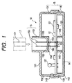
- Fig. 1 is a cross-sectional view of a branch connection box according to one embodiment of the present invention and Fig. 2 is an exploded perspective view thereof.
- the branch connection box 10 includes a case 11 made of resilient material such as synthetic resin or the like and a circuit board 12 made of a resilient material such as synthetic resin or the like which is accommodated in the inside of the case 11.
- the case 11 includes an upper case 13 and a lower case 14 and is constructed by combining them with each other with a fitting engagement under the condition that respective openings 133, 143 which will be explained later face each other in an opposed manner.
- the upper case 13 is comprised of a main wall 131 and a circumferential wall 132 which is integrally formed on the peripheral edge of the main wall 131 and an opening 133 is formed at the lower face of the upper case 13.
- a connector housing 151 is integrally formed on the main wall 131.
- the connector housing 151 is formed such that a bottom wall 152 thereof is recessed toward the opening 133 side, the bottom wall 152 may be formed on the same plane as the main wall 131. In both cases, the bottom wall 152 constitutes a portion of the main wall 131.
- a plurality of elongated male connector terminals 153 which are formed by punching a metal sheet or the like are fixedly secured to a bottom wall 152 (that is, the main wall 131) of the connector housing 151, wherein one end sides of the connector terminals 153 are positioned in the outside of the case 11 within the connector housing 151, while the other end sides of the connector terminals 153 are positioned in the inside of the case 11.
- the connector terminals 153 are fixedly secured to the bottom wall 152 by inserting the connector terminals 153 into through holes 154 which are formed in the bottom wall 152 and have a cross section slightly smaller than the transverse cross section of the connector terminals 153 or by other methods.
- the connector terminals 153 are provided with widened flange portions 155 and positioning of the connector terminals 153 in an axial direction is carried out by inserting these flange portions 155 into the through holes 154 under pressure.
- the connector 15 is integrally formed with the case 11.
- the lower case 14 is comprised of a main wall 141 and a peripheral wall 142 which is integrally formed with the periphery of the main wall 141 and is provided with an opening 143 at an upper face thereof.
- a shoulder portion 144 for allowing the circuit board 12 to be placed thereon is formed on the inner periphery of the opening 143.
- circuit board 12 On the circuit board 12, given wiring conductors which are not shown in drawings are arranged and a plurality of chip-type or lead-line type electronic components 121 are mounted on the circuit board 12 such that they are connected to the wiring conductors by soldering or the like.
- the circuit board 12 is provided with a plurality of through holes 122 in which the other ends of the connector terminals 153 fixedly secured to the upper case 13 are inserted.
- lands which are connected to the wiring conductors although not shown in drawings are formed.
- the other ends of the connector terminals 153 which are inserted into the respective through holes 122 are fixedly secured to the respective lands by soldering or the like.
- a plurality of protrusions 145 which are described previously are formed at positions which surround a plurality of contact portions where respective connector terminals 153 are fixedly secured to the circuit board 12 and are adjacent to such portions.
- the branch connection box 10 having such a constitution is assembled such that the other ends of the connector terminals 153 which are supported by the upper case 13 are made to pass through the through holes 122 of the circuit board 12 and are fixedly secured to the circuit board 12 by soldering or the like, then the opening 133 of the upper case 13 and the opening 143 of the lower case 14 are engaged with each other using a fitting engagement, and the upper case 13 and the lower case 14 are integrally joined by screws or a given engagement.
- the circuit board 12 is brought into contact with the shoulder portion 144 of the lower case 14 and the protrusions 145 and hence, the circuit board 12 is brought into a fixed condition in the inside of the case 11.
- the branch connection box 10 having the above-mentioned constitution, at the time of mounting the external connector 17 in the inside of the connector housing 151 and inserting a female connector terminal 171 into the male connector terminals 153 under pressure, even if the upper case 13 is pressed toward the circuit board 12 side, the circuit board 12 is brought into contact with the protrusions 145 formed on the lower case 14 and is not deflected and hence, no stress is generated at the portion where the connector terminals 153 are fixedly secured to the circuit board 12. Accordingly, problems such that cracks occur at the fixedly securing portions and the lands are peeled off thus giving rise to a disconnection can be eliminated. Further, problems such that the electrical connection of electrical components 121 mounted on the circuit board 12 with the circuit board 12 is disconnected and the electronic components 121 per se are ruptured can be eliminated.
- the protrusions 145 are formed at the contact positions which are adjacent to the portions where the connector terminals 153 are fixedly secured to the circuit board 12, the protrusions 145 may be formed at positions a given distance away from such a fixedly securing portions.
- the circuit board is liable to be deflected and hence, the allowable distance which can be shifted away from the fixedly securing portions is determined by the degree of deflection which depends on the kind of material and the thickness of the circuit board 12.
- the protrusions 145 are integrally formed with the lower case 14, the protrusions 145 may be individually formed of insulating material such as synthetic resin, ceramic or the like and thereafter may be fixedly secured to the lower case 14 by an adhesive or screw means. In any case, by integrally forming the protrusions 145 with the lower case 14, the protrusions 145 can have the given length and hence, the circuit board 12 can be assuredly brought into contact with the protrusions 145 thus effectively preventing the deflection of the circuit board 12.
- the protrusions 145 may be formed to have a length which makes the protrusions 145 slightly away from the circuit board 12 under the condition that the pressing force toward the circuit board 12 side is not yet applied to the upper case 13. In such a case, also, under the condition that the pressing force is applied to the upper case 13, the circuit board 12 is readily brought into contact with the protrusions 145 and hence, the deflection of the circuit board 12 can be effectively prevented.
- Fig. 3 is a longitudinal cross-sectional view of the branch connection box according to the second embodiment of the present invention
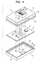
- Fig. 4 is an exploded perspective view of the branch connection box.
- constituting parts which are equal to those parts of the first embodiment are denoted by same reference numerals and hence, the detailed explanation thereof is omitted and the embodiment is explained hereinafter focusing on the points which are different from the first embodiment.
- the branch connection box 10' according to the second embodiment includes a case 11 which is comprised of an upper case 13 and a lower case 14 and a circuit board 12 which is accommodated in the inside of the case 11 in a fixedly secured condition.
- first protrusions 145 On a bottom wall 152 (that is, a main wall 131) of a connector housing 151 disposed in the inside of the upper case 13 and at positions corresponding to respective protrusions 145 formed on the lower case 14 (hereinafter called first protrusions 145), a plurality (four in this embodiment) of rod-like second protrusions 134 which extend to positions where protrusions 134 are brought into contact with the circuit board 12 and constitute deflection prevention means are formed by an integral molding.
- the branch connection box 10' having such a constitution, even if the upper case 13 is pressed toward the circuit board 12 side at the time of inserting an external connector terminal 171 into the connector terminals 153 under pressure, the first protrusions 145 and the second protrusions 134 are brought into contact with each other by way of the circuit board 12 and hence, the deflection of the case can be prevented and accordingly the deflection of the circuit board 12 can be prevented.
- the circuit board 12 is brought into contact with the second protrusions 134 and hence, the deflection of the circuit board 12 can be prevented and any inconveniences which give rise to due to the deflection of the circuit board 12 can be obviated.
- the second protrusions 134 are formed at positions which correspond to the first protrusions 145 in this embodiment, the second protrusions 134 may be formed at positions shifted from the first protrusions 145 in a planar direction of the circuit board 12. Even in such a case, the second protrusions 134 are brought into contact with the circuit board 12 supported by the first protrusions 145 and hence, the deflection of the case is prevented and accordingly the circuit board 12 is not deflected.
- first protrusions 145 and the second protrusions 134 are formed at the contact positions which are adjacent to the portions where the connector terminals 153 are fixedly secured to the circuit board 12, the protrusions 145, 134 may be formed at positions a given distance away from such fixedly securing portions.
- the circuit board 12 is liable to be deflected and hence, the allowable distance which can be shifted away from the fixedly securing portions is determined by the degree of deflection which depends on the kind of material and the thickness of the circuit board 12.
- the second protrusions 134 are integrally formed with the upper case 13
- the second protrusions 134 may be individually formed of insulating material such as synthetic resin, ceramic or the like and thereafter may be fixedly secured to the upper case 13 by an adhesive or screw means.
- the second protrusions 134 can have the given length and hence, the second protrusions 134 can be assuredly brought into contact with the circuit board 12 thus effectively preventing the deflection of the case.
- the second protrusions 134 may be formed to have a length which shifts the protrusions 145 slightly away from the circuit board 12 under the condition that the pressing force toward the circuit board 12 side is not yet applied to the upper case 13. In such a case, also, under the condition that the pressing force is applied to the upper case 13, the circuit board 12 is readily brought into contact with the second protrusions 134 and hence, the deflection of the upper case 13 can be effectively prevented.
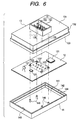
- Fig. 5 is a longitudinal cross-sectional view of the branch connection box according to the third embodiment of the present invention and Fig. 6 is an exploded perspective view of the branch connection box.
- constituting parts which are equal to those parts of the first embodiment are denoted by same reference numerals and hence, the detailed explanation thereof is omitted and the embodiment is explained hereinafter focusing on the points which are different from the first embodiment.
- the branch connection box 10'' according to the third embodiment includes a case 11 which is comprised of an upper case 13 and a lower case 14 and a circuit board 12 which is accommodated in the inside of the case 11 in a fixedly secured condition.
- a plurality (four in this embodiment) of rod-like protrusions 135 which extend to the circuit board 12 side and constitute the deflection prevention means are formed on a bottom wall 152 (that is, a main wall 131) of a connector housing 151 by an integral molding, while in the inside of the lower case 14, a plurality (four in this embodiment) of rod-like protrusions 146 which extend to the circuit board 12 side and constitute the deflection prevention means are formed at positions corresponding to the protrusions 135.
- protrusions 135, 146 are formed at contact positions which surround and are adjacent to a plurality of portions where connector terminals 153 are fixedly secured to the circuit board 12 and the protrusions 135, 146 are brought into contact with each other by way of a plurality of through holes 123 formed in the circuit board 12.
- the through holes 123 have a diameter larger than the transverse cross sections of the protrusions 135, 146 and hence, even if the position of the circuit board 12 is shifted or the like, the protrusions 135, 146 can be brought into contact with each other.
- both protrusions 135, 146 are brought into contact with each other by way of the through holes 123 of the circuit board 12 and hence, the deflection of the case can be prevented and accordingly the circuit board 12 is not deflected.
- both protrusions 135 and 146 are formed at positions which are adjacent to portions where the connector terminals 153 are fixedly secured to the circuit board 12 in this embodiment, the protrusions 135 and 146 may be formed at positions shifted a given distance from such fixedly securing portions.
- the protrusions 135, 146 are formed at positions excessively away from the fixedly securing portions, the circuit board 12 is liable to be deflected and hence, the allowable distance which can be shifted away from the fixedly securing portions is determined by the degree of deflection which depends on the kind of material and the thickness of the circuit board 12.
- the protrusions 135 are integrally formed with the upper case 13 and the protrusions 146 are integrally formed with the lower case 14, the protrusions 135, 146 may be individually formed of insulating material such as synthetic resin, ceramic or the like and thereafter may be fixedly secured to the upper case 13 and the lower case 14 by an adhesive or screw means.
- the protrusions 135, 146 can have the given length and hence, both protrusions 135, 146 can be assuredly brought into contact with the circuit board 12 thus the deflection of the case can be effectively prevented.
- both protrusions 135 and 146 may be formed to have a length which makes the protrusions 135 and 146 slightly away from the circuit board 12 under the condition that the pressing force toward the circuit board 12 side is not yet applied to the upper case 13. In such a case, also, under the condition that the pressing force is applied to the upper case 13, the circuit board 12 is readily brought into contact with both protrusions 135, 146 and hence, the deflection of the upper case 13 can be effectively prevented.
- the connector terminals 153 fixedly mounted on the upper case 13 are of a male type
- the connector terminals 153 may be of a female type.
- the connector terminal 171 of the external connector 17 becomes a male type.
- the upper case 13 and the lower case 14 are formed in recesses having openings, either one of them may adopt a plate-like shape. What is important is that the case is constructed by combining the upper case 13 and the lower case 14.
- any one of the protrusions 134, 135, 146, 145 are made of four rod-like protrusions, the shape and the number of the protrusions can be arbitrarily determined.
- the branch connection box of the present invention can be also used as a junction box of an automobile which accommodates a bus bar board or the like in the case 11.
- the deflection prevention means for preventing the deflection of the case generated upon inserting an external connector terminal into the connector terminals under pressure is integrally formed with the case, and hence the branch connection box which can assuredly prevent the deflection of the case which occur at the time of inserting the external connector terminal into the connector terminals under pressure can be realized.
- the case is comprised of the first case member and the second case member, the connector terminals are fixedly mounted on the first case member, the circuit board is accommodated in the case such that the one surface of the circuit board faces the first case member in an opposed manner and the other surface of the circuit board faces the second case member in an opposed manner, and hence the branch connection box where the case can be easily constructed, the connector can be easily and integrally formed with the case, and the circuit board can be easily accommodated in the case can be realized.
- the deflection prevention means is comprised of a plurality of protrusions formed on the second case member such that the protrusions are brought into contact with the other surface of the circuit board and hence, a branch connection box where even if the case is pressed toward the circuit board side at the time of inserting the external connector terminal into the connector terminals under pressure, the deflection of the case can be effectively prevented can be realized.
- a plurality of protrusions are formed such that the protrusions are brought into contact with the circuit board at positions adjacent to portions where the connector terminals are fixedly secured to the circuit board, and hence a branch connection box where even if the case is pressed to the circuit board side, the deflection of the case can be effectively prevented can be realized.
- the deflection prevention means includes a plurality of second protrusions integrally formed on the first case member such that the second protrusions are brought into contact with one surface of the circuit board in addition to a plurality of first protrusions formed on the second case member, and hence a branch connection box even if the case is pressed toward the circuit board side, the deflection of the case can be further assuredly prevented can be realized.
- a plurality of second protrusions are formed such that the second protrusions respectively face a plurality of first protrusions in an opposed manner and hence, the occurrence of unnecessary stress on the circuit board can be effectively prevented.
- the deflection prevention means is comprised of a plurality of protrusions integrally formed on the first case member and a plurality of protrusions integrally formed on the second case member, and the protrusions of the first case member and the protrusions of the second case member are brought into contact with each other by way of through holes formed in the circuit board and hence, a branch connection box where even if the case is pressed toward the circuit board side, no unnecessary pressing force acts on the circuit board thus effectively preventing the deflection of the case can be realized.
- the protrusions of the first case member and the protrusions of the second case member are formed such that both protrusions are brought into contact with each other at positions adjacent to portions where the connector terminals are fixedly secured to the circuit board and hence, a branch connection box where the protrusions of the first case member and the protrusions of the second case member are brought into contact with each other in a narrow range in open face directions of the first case member and the second case member so that the deflection of the case can be assuredly prevented can be realized.
Landscapes
- Connection Or Junction Boxes (AREA)
- Casings For Electric Apparatus (AREA)
- Mounting Of Printed Circuit Boards And The Like (AREA)
- Coupling Device And Connection With Printed Circuit (AREA)
Abstract
Description
Claims (8)
- A branch connection box, comprising:a case in which a circuit board is fixedly accomodated;a plurality of connector terminals fixedly mounted to said case, said connector terminals having respective one ends thereof positioned outside said case and respective other ends thereof disposed inside said case, said respective other ends of said connector terminals being fixedly secured to the circuit board; anddeflection prevention means for preventing the deflection of said case generated upon inserting an external connector terminal into said connector terminals under pressure, said deflection prevention means being integrally formed with said case.
- A branch connection box according to claim 1, wherein said case comprises a first case member and a second case member, said connector terminals are fixedly mounted on said first case member, said circuit board is accommodated in said case such that one surface of said circuit board faces said first case member in an opposed manner and the other surface of said circuit board faces said second case member in an opposed manner.
- A branch connection box according to claim 2, wherein said deflection prevention means comprises a plurality of protrusions formed on said second case member such that said protrusions are brought into contact with the other surface of said circuit board.
- A branch connection box according to claim 3, wherein a plurality of said protrusions are formed such that said protrusions are brought into contact with said circuit board at positions adjacent to portions where said connector terminals are fixedly secured to said circuit board.
- A branch connection box according to claim 3, wherein said deflection prevention means includes a plurality of second protrusions formed on said first case member such that said second protrusions are brought into contact with one surface of said circuit board in addition to a plurality of first protrusions formed on said second case member.
- A branch connection box according to claim 5, wherein a plurality of said second protrusions are formed such that said second protrusions respectively face a plurality of said first protrusions in an opposed manner by way of said circuit board.
- A branch connection box according to claim 2, wherein said deflection prevention means comprises a plurality of protrusions integrally formed on said first case member and a plurality of protrusions integrally formed on said second case member, and said protrusions of said first case member and said protrusions of said second case member are brought into contact with each other by way of thorough holes formed in said circuit board.
- A branch connection box according to claim 7, wherein said protrusions of said first case member and said protrusions of said second case member are formed such that both protrusions are brought into contact with each other at positions adjacent to portions where said connector terminals are fixedly secured to said circuit board.
Applications Claiming Priority (2)
| Application Number | Priority Date | Filing Date | Title |
|---|---|---|---|
| JP06700899A JP3673422B2 (en) | 1999-03-12 | 1999-03-12 | Branch connection box |
| JP6700899 | 1999-03-12 |
Publications (3)
| Publication Number | Publication Date |
|---|---|
| EP1034983A2 true EP1034983A2 (en) | 2000-09-13 |
| EP1034983A3 EP1034983A3 (en) | 2001-05-16 |
| EP1034983B1 EP1034983B1 (en) | 2003-08-13 |
Family
ID=13332477
Family Applications (1)
| Application Number | Title | Priority Date | Filing Date |
|---|---|---|---|
| EP20000105085 Expired - Lifetime EP1034983B1 (en) | 1999-03-12 | 2000-03-10 | Branch connection box |
Country Status (3)
| Country | Link |
|---|---|
| EP (1) | EP1034983B1 (en) |
| JP (1) | JP3673422B2 (en) |
| DE (1) | DE60004418T2 (en) |
Cited By (12)
| Publication number | Priority date | Publication date | Assignee | Title |
|---|---|---|---|---|
| EP1460723A3 (en) * | 2003-03-21 | 2005-04-27 | The Boeing Company | Connector interface pad for structurally integrated wiring |
| EP1618770A4 (en) * | 2003-04-28 | 2009-01-07 | Motorola Inc | Electronic control module for a removable connector and methods of assembling same |
| WO2010000524A1 (en) | 2008-07-03 | 2010-01-07 | Robert Bosch Gmbh | Control unit for personal protection means for a vehicle and method for assembling such a control unit |
| US8971047B2 (en) | 2011-09-28 | 2015-03-03 | Samsung Electronics Co., Ltd. | Printed circuit board assembly |
| CN104871410A (en) * | 2013-02-20 | 2015-08-26 | 三菱重工汽车空调系统株式会社 | Inverter-integrated electric compressor |
| CN105075095A (en) * | 2013-04-26 | 2015-11-18 | 三菱重工汽车空调系统株式会社 | Inverter-integrated electric compressor |
| RU2593597C1 (en) * | 2014-01-24 | 2016-08-10 | Эбершпехер Клаймит Контрол Системз Гмбх Унд Ко. Кг | Control unit for vehicle heating device |
| US9585253B2 (en) | 2015-03-05 | 2017-02-28 | Denso Corporation | Electronic device |
| US9722474B2 (en) | 2013-02-21 | 2017-08-01 | Mitsubishi Heavy Industries Automotive Thermal Systems Co., Ltd. | Inverter-integrated electric compressor |
| US9735644B2 (en) | 2012-12-11 | 2017-08-15 | Mitsubishi Heavy Industries Automotive Thermal Systems Co., Ltd. | Inverter-integrated electric compressor |
| US10122237B2 (en) | 2013-03-07 | 2018-11-06 | Mitsubishi Heavy Industries Thermal Systems, Ltd. | Inverter circuit board and inverter-containing electric compressor using same |
| EP3675298B1 (en) * | 2018-12-28 | 2023-03-01 | Yazaki Corporation | Electrical connection box |
Families Citing this family (25)
| Publication number | Priority date | Publication date | Assignee | Title |
|---|---|---|---|---|
| JP2000294961A (en) * | 1999-04-01 | 2000-10-20 | Harness Syst Tech Res Ltd | Joint box case and joint box assembling method |
| US20060077640A1 (en) * | 2002-05-14 | 2006-04-13 | Sumitomo Electric Industries, Ltd. | Optical module |
| JP2004247700A (en) * | 2002-05-14 | 2004-09-02 | Sumitomo Electric Ind Ltd | Optical module |
| JP2005130633A (en) * | 2003-10-24 | 2005-05-19 | Yazaki Corp | Electrical junction box |
| KR101108050B1 (en) * | 2004-11-10 | 2012-01-25 | 엘지전자 주식회사 | Remote monitor device of home appliance |
| JP2006331803A (en) * | 2005-05-25 | 2006-12-07 | Denso Corp | Electronic control device |
| JP2010251644A (en) * | 2009-04-20 | 2010-11-04 | Denso Wave Inc | Security device |
| JP5587152B2 (en) * | 2010-11-30 | 2014-09-10 | 住友電装株式会社 | Electrical junction box |
| WO2013008632A1 (en) * | 2011-07-11 | 2013-01-17 | 日本電気株式会社 | Piezoelectric vibration sensor |
| JP2014154474A (en) * | 2013-02-13 | 2014-08-25 | Panasonic Corp | Usb receptacle |
| DE102013003800A1 (en) * | 2013-03-05 | 2014-09-11 | Wabco Gmbh | Housing for receiving a printed circuit board with at least one connector interface, electronic module with such housing, motor vehicle and method for producing such a housing or electronic module |
| KR101636288B1 (en) * | 2014-12-23 | 2016-07-06 | 주식회사 유라코퍼레이션 | Junction box |
| JP6544181B2 (en) * | 2015-09-29 | 2019-07-17 | 株式会社デンソー | Electronic control unit |
| JP6542642B2 (en) * | 2015-11-11 | 2019-07-10 | 日立オートモティブシステムズ株式会社 | Electronic control unit |
| JP6827212B2 (en) * | 2016-12-20 | 2021-02-10 | パナソニックIpマネジメント株式会社 | Sensor device and lighting equipment |
| JP6890275B2 (en) * | 2017-07-20 | 2021-06-18 | パナソニックIpマネジメント株式会社 | USB outlet |
| JP7081250B2 (en) * | 2018-03-22 | 2022-06-07 | 株式会社デンソー | Power converter |
| JP7076265B2 (en) * | 2018-04-03 | 2022-05-27 | スリーエム イノベイティブ プロパティズ カンパニー | connector |
| KR102151781B1 (en) * | 2019-03-07 | 2020-09-03 | 엘에스일렉트릭(주) | Structure for supporting PCB |
| JP7289107B2 (en) * | 2019-03-11 | 2023-06-09 | パナソニックIpマネジメント株式会社 | USB outlet |
| JP7317689B2 (en) * | 2019-12-20 | 2023-07-31 | 矢崎総業株式会社 | Electrical junction box, wire harness, and electrical junction box manufacturing method |
| JP7378897B2 (en) * | 2019-12-20 | 2023-11-14 | 矢崎総業株式会社 | Electrical junction box and wire harness |
| JP2020113790A (en) * | 2020-04-03 | 2020-07-27 | パナソニックIpマネジメント株式会社 | USB outlet |
| KR102518754B1 (en) * | 2021-04-07 | 2023-04-06 | 주식회사 경신 | Junction-box of vehicle |
| JP7732867B2 (en) * | 2021-11-18 | 2025-09-02 | 矢崎総業株式会社 | Electrical connectors and electrical junction boxes |
Family Cites Families (4)
| Publication number | Priority date | Publication date | Assignee | Title |
|---|---|---|---|---|
| JPS6261856A (en) * | 1985-09-12 | 1987-03-18 | Yazaki Corp | Wiring device assembled with functions for automobile |
| JPH0614475B2 (en) * | 1989-06-09 | 1994-02-23 | 矢崎総業株式会社 | Connection structure of bus bar and insulation displacement terminal for branch in electric junction box |
| DE3936906C2 (en) * | 1989-11-06 | 1995-02-02 | Telefunken Microelectron | Housing for automotive electronics |
| JP3405249B2 (en) * | 1999-02-01 | 2003-05-12 | 住友電装株式会社 | Electrical junction box |
-
1999
- 1999-03-12 JP JP06700899A patent/JP3673422B2/en not_active Expired - Fee Related
-
2000
- 2000-03-10 EP EP20000105085 patent/EP1034983B1/en not_active Expired - Lifetime
- 2000-03-10 DE DE2000604418 patent/DE60004418T2/en not_active Expired - Lifetime
Cited By (19)
| Publication number | Priority date | Publication date | Assignee | Title |
|---|---|---|---|---|
| EP1460723A3 (en) * | 2003-03-21 | 2005-04-27 | The Boeing Company | Connector interface pad for structurally integrated wiring |
| EP1618770A4 (en) * | 2003-04-28 | 2009-01-07 | Motorola Inc | Electronic control module for a removable connector and methods of assembling same |
| WO2010000524A1 (en) | 2008-07-03 | 2010-01-07 | Robert Bosch Gmbh | Control unit for personal protection means for a vehicle and method for assembling such a control unit |
| US8693205B2 (en) | 2008-07-03 | 2014-04-08 | Robert Bosch Gmbh | Control unit for personal protection device for a vehicle and method for assembling such a control unit |
| US8971047B2 (en) | 2011-09-28 | 2015-03-03 | Samsung Electronics Co., Ltd. | Printed circuit board assembly |
| DE112013005919B4 (en) | 2012-12-11 | 2019-08-14 | Mitsubishi Heavy Industries Thermal Systems, Ltd. | Electric compressor with integrated inverter |
| US9735644B2 (en) | 2012-12-11 | 2017-08-15 | Mitsubishi Heavy Industries Automotive Thermal Systems Co., Ltd. | Inverter-integrated electric compressor |
| CN104871410A (en) * | 2013-02-20 | 2015-08-26 | 三菱重工汽车空调系统株式会社 | Inverter-integrated electric compressor |
| US9948165B2 (en) | 2013-02-20 | 2018-04-17 | Mitsubishi Heavy Industries Automotive Thermal Systems Co., Ltd. | Inverter-integrated electric compressor |
| CN104871410B (en) * | 2013-02-20 | 2017-09-01 | 三菱重工汽车空调系统株式会社 | Inverter-integrated electric compressor |
| US9722474B2 (en) | 2013-02-21 | 2017-08-01 | Mitsubishi Heavy Industries Automotive Thermal Systems Co., Ltd. | Inverter-integrated electric compressor |
| US10122237B2 (en) | 2013-03-07 | 2018-11-06 | Mitsubishi Heavy Industries Thermal Systems, Ltd. | Inverter circuit board and inverter-containing electric compressor using same |
| CN105075095B (en) * | 2013-04-26 | 2017-08-25 | 三菱重工汽车空调系统株式会社 | Inverter-integrated electric compressor |
| US10122247B2 (en) | 2013-04-26 | 2018-11-06 | Mitsubishi Heavy Industries Thermal Systems, Ltd. | Inverter-integrated electric compressor |
| CN105075095A (en) * | 2013-04-26 | 2015-11-18 | 三菱重工汽车空调系统株式会社 | Inverter-integrated electric compressor |
| US9472906B2 (en) | 2014-01-24 | 2016-10-18 | Eberspächer Climate Control Systems GmbH & Co. KG | Control device for a vehicle heater |
| RU2593597C1 (en) * | 2014-01-24 | 2016-08-10 | Эбершпехер Клаймит Контрол Системз Гмбх Унд Ко. Кг | Control unit for vehicle heating device |
| US9585253B2 (en) | 2015-03-05 | 2017-02-28 | Denso Corporation | Electronic device |
| EP3675298B1 (en) * | 2018-12-28 | 2023-03-01 | Yazaki Corporation | Electrical connection box |
Also Published As
| Publication number | Publication date |
|---|---|
| DE60004418D1 (en) | 2003-09-18 |
| EP1034983B1 (en) | 2003-08-13 |
| JP2000261160A (en) | 2000-09-22 |
| DE60004418T2 (en) | 2004-03-11 |
| JP3673422B2 (en) | 2005-07-20 |
| EP1034983A3 (en) | 2001-05-16 |
Similar Documents
| Publication | Publication Date | Title |
|---|---|---|
| EP1034983B1 (en) | Branch connection box | |
| EP1005109B1 (en) | Electronic control unit with electrical connector | |
| CA1069197A (en) | Solderless electrical contact | |
| US5951336A (en) | Terminal fitting | |
| US10741973B2 (en) | Electrical cable connector | |
| US7118409B2 (en) | Connector and cable retainer | |
| KR102875482B1 (en) | Cable protection cover for increasing pull-out resistance | |
| EP0657959B1 (en) | Electrical connector assembly for mounting on a printed circuit board | |
| US20050272278A1 (en) | Electrical terminal connection, especially for connecting an outer conductior of a coaxial cable | |
| EP0874419B1 (en) | Connector plug | |
| KR20010085187A (en) | Terminal | |
| US20220069488A1 (en) | Harness component | |
| KR20050085717A (en) | Flexible cable electrical connector | |
| US6309244B1 (en) | Connector assembly and power shunt contact | |
| US4569566A (en) | Plug and receptacle connector assembly | |
| US7131874B2 (en) | Electrical connector having first and second terminals | |
| US20220045446A1 (en) | Harness component | |
| US6488541B1 (en) | Connector | |
| US6530786B2 (en) | Printed circuit board-connecting connector | |
| US6340321B2 (en) | Electrical connector | |
| US5879183A (en) | Press-connecting terminal | |
| US6494738B2 (en) | Electric-wire holding structure | |
| CA2225219C (en) | Electrical connector with pin retention | |
| JP4597750B2 (en) | Female terminal fittings and connectors | |
| JPH0461773A (en) | Structure of connector mounting part |
Legal Events
| Date | Code | Title | Description |
|---|---|---|---|
| PUAI | Public reference made under article 153(3) epc to a published international application that has entered the european phase |
Free format text: ORIGINAL CODE: 0009012 |
|
| AK | Designated contracting states |
Kind code of ref document: A2 Designated state(s): DE FR GB |
|
| AX | Request for extension of the european patent |
Free format text: AL;LT;LV;MK;RO;SI |
|
| PUAL | Search report despatched |
Free format text: ORIGINAL CODE: 0009013 |
|
| AK | Designated contracting states |
Kind code of ref document: A3 Designated state(s): AT BE CH CY DE DK ES FI FR GB GR IE IT LI LU MC NL PT SE |
|
| AX | Request for extension of the european patent |
Free format text: AL;LT;LV;MK;RO;SI |
|
| RIC1 | Information provided on ipc code assigned before grant |
Free format text: 7B 60R 16/02 A, 7H 01R 9/24 B, 7H 01R 13/703 B, 7H 05K 1/18 B |
|
| 17P | Request for examination filed |
Effective date: 20010626 |
|
| AKX | Designation fees paid |
Free format text: DE FR GB |
|
| 17Q | First examination report despatched |
Effective date: 20020125 |
|
| GRAH | Despatch of communication of intention to grant a patent |
Free format text: ORIGINAL CODE: EPIDOS IGRA |
|
| RAP1 | Party data changed (applicant data changed or rights of an application transferred) |
Owner name: AUTONETWORKS TECHNOLOGIES, LTD. Owner name: SUMITOMO ELECTRIC INDUSTRIES, LTD. Owner name: SUMITOMO WIRING SYSTEMS, LTD. |
|
| GRAA | (expected) grant |
Free format text: ORIGINAL CODE: 0009210 |
|
| GRAS | Grant fee paid |
Free format text: ORIGINAL CODE: EPIDOSNIGR3 |
|
| AK | Designated contracting states |
Designated state(s): DE FR GB |
|
| REG | Reference to a national code |
Ref country code: GB Ref legal event code: FG4D |
|
| REF | Corresponds to: |
Ref document number: 60004418 Country of ref document: DE Date of ref document: 20030918 Kind code of ref document: P |
|
| ET | Fr: translation filed | ||
| PLBE | No opposition filed within time limit |
Free format text: ORIGINAL CODE: 0009261 |
|
| STAA | Information on the status of an ep patent application or granted ep patent |
Free format text: STATUS: NO OPPOSITION FILED WITHIN TIME LIMIT |
|
| 26N | No opposition filed |
Effective date: 20040514 |
|
| PGFP | Annual fee paid to national office [announced via postgrant information from national office to epo] |
Ref country code: GB Payment date: 20090304 Year of fee payment: 10 |
|
| PGFP | Annual fee paid to national office [announced via postgrant information from national office to epo] |
Ref country code: FR Payment date: 20090316 Year of fee payment: 10 |
|
| GBPC | Gb: european patent ceased through non-payment of renewal fee |
Effective date: 20100310 |
|
| REG | Reference to a national code |
Ref country code: FR Ref legal event code: ST Effective date: 20101130 |
|
| PG25 | Lapsed in a contracting state [announced via postgrant information from national office to epo] |
Ref country code: FR Free format text: LAPSE BECAUSE OF NON-PAYMENT OF DUE FEES Effective date: 20100331 |
|
| PG25 | Lapsed in a contracting state [announced via postgrant information from national office to epo] |
Ref country code: GB Free format text: LAPSE BECAUSE OF NON-PAYMENT OF DUE FEES Effective date: 20100310 |
|
| PGFP | Annual fee paid to national office [announced via postgrant information from national office to epo] |
Ref country code: DE Payment date: 20130306 Year of fee payment: 14 |
|
| REG | Reference to a national code |
Ref country code: DE Ref legal event code: R119 Ref document number: 60004418 Country of ref document: DE |
|
| REG | Reference to a national code |
Ref country code: DE Ref legal event code: R119 Ref document number: 60004418 Country of ref document: DE Effective date: 20141001 |
|
| PG25 | Lapsed in a contracting state [announced via postgrant information from national office to epo] |
Ref country code: DE Free format text: LAPSE BECAUSE OF NON-PAYMENT OF DUE FEES Effective date: 20141001 |