EP1034823A2 - Amusement machine with movable seat - Google Patents
Amusement machine with movable seat Download PDFInfo
- Publication number
- EP1034823A2 EP1034823A2 EP00200632A EP00200632A EP1034823A2 EP 1034823 A2 EP1034823 A2 EP 1034823A2 EP 00200632 A EP00200632 A EP 00200632A EP 00200632 A EP00200632 A EP 00200632A EP 1034823 A2 EP1034823 A2 EP 1034823A2
- Authority
- EP
- European Patent Office
- Prior art keywords
- seat
- child
- movable seat
- crank mechanism
- control system
- Prior art date
- Legal status (The legal status is an assumption and is not a legal conclusion. Google has not performed a legal analysis and makes no representation as to the accuracy of the status listed.)
- Granted
Links
- 230000002596 correlated effect Effects 0.000 claims abstract description 7
- 230000003387 muscular Effects 0.000 claims abstract description 5
- 230000001276 controlling effect Effects 0.000 claims description 4
- 238000005259 measurement Methods 0.000 claims description 2
- 230000005540 biological transmission Effects 0.000 description 4
- 230000000875 corresponding effect Effects 0.000 description 2
- 239000012530 fluid Substances 0.000 description 2
- 238000012986 modification Methods 0.000 description 2
- 230000004048 modification Effects 0.000 description 2
- 230000007423 decrease Effects 0.000 description 1
- 230000001419 dependent effect Effects 0.000 description 1
- 230000005611 electricity Effects 0.000 description 1
- 230000009347 mechanical transmission Effects 0.000 description 1
- 230000000630 rising effect Effects 0.000 description 1
- 238000005096 rolling process Methods 0.000 description 1
Images


Classifications
-
- A—HUMAN NECESSITIES
- A63—SPORTS; GAMES; AMUSEMENTS
- A63G—MERRY-GO-ROUNDS; SWINGS; ROCKING-HORSES; CHUTES; SWITCHBACKS; SIMILAR DEVICES FOR PUBLIC AMUSEMENT
- A63G31/00—Amusement arrangements
- A63G31/16—Amusement arrangements creating illusions of travel
Definitions
- This invention relates to an amusement machine comprising at least one movable seat having typically a pleasing and captivating form (for example having the form of a vehicle), carried by a movable structure arranged to movingly transport a child (or a user generally), and mover means for moving the movable structure.
- An object of the invention is to provide a machine of the stated type, in which the user can interact with the seat movement to derive amusement or pleasure therefrom.
- the invention provides an amusement machine having, applied to the seat, a crank mechanism to be operated by the muscular force of the child, and a control system for the machine movements which is able to vary one or more characteristics of the seat movement in a manner correlated with the speed with which the crank mechanism is operated by the child seated on the seat.
- said crank mechanism comprises a wheel or other rotary body rotated by the action of the child on the crank mechanism, the control system comprising means for measuring the rotational speed of said wheel or rotary body, and a controlling microprocessor connected to said measurement means to vary, via inverter means, characteristics of the seat movement in a manner correlated with the speed with which the crank mechanism is rotated.
- the seat also comprises a pedalled crank which operates said wheel, and is operated by the legs of the child carried by the seat.
- the machine comprises a movable seat, on which the child sits via a seating portion 11, in such a manner as to be movably transported with it.
- This seat preferably has a form which is pleasurable and attractive for the child, for example the form of a vehicle driving seat.
- the seat 10 is carried by a movable structure 20 able to movingly transport a child, and with which mover means for moving the structure 20 are associated.
- a fixed base 15 comprising an annularly extending rail 16 which rests on the ground.
- the rail 16 supports a movable base 21 provided with idle wheels which roll along the rail 16. While rolling along the rail 16, the movable base 21 is constrained to rotate about a vertical axis A by means of a vertical pin 22 fixed to the centre of the base 21 and coupled to a bush 17 rigid with the fixed base 15.
- the movable base 21 is connected to mover means for rotating the base 21 about the axis A.
- the movable base 21 carries a geared motor 23 which operates a sprocket 24 connected by a transmission chain 25 to a sprocket 26 of vertical axis fixed to the bush 17.
- the movable base 21 supports said movable structure 20 via interposed raising means 40.
- Said raising means 40 are substantially identical to those used in fork lift trucks.
- Said means 40 comprise a pair of vertical rails 41 fixed to the movable base 21 at their lower ends and fixed together by a horizontal cross-member 41a.
- a vertical rectangular frame 42 is positioned between the two rails 41 and is vertically slidable along these rails 41, to which it is slidingly constrained by idle wheels 42a.
- the two vertical sides 43 of the frame 42 define two vertical rails, between which there is positioned a carriage 44 slidable vertically along these rails, to which it is slidingly constrained by idle wheels 44a.
- the means 40 also comprise a cylinder-piston unit 45 of vertical axis, having its cylinder fixed to the cross-member 41a, its rod extending upwards and fixed at its upper end to a cross-member 42b of the frame 42.
- a transmission chain 46 is provided having one end fixed to the fixed cross-member 41a and its other end fixed to the movable carriage 44. The chain 46 passes about an idle sprocket 47 pivoted to the upper cross-member 42c of the movable frame 42.
- every movement of the rod of the cylinder-piston unit 45 produces a corresponding movement of the carriage 44 but of double the length.
- the movable structure 20 is fixed to said carriage 44, and is hence raised in a vertical direction by the action of the cylinder-piston unit 45.
- the movable structure 20 carries the entire movable seat 10, which in addition to the seating portion 11 comprises a crank mechanism 30 to be driven by the muscular force of the child.
- the crank mechanism 30 comprises a (double) crank 31 with pedals 32, which is positioned in the front part of the seat 10 in front of the seating portion 11 and is operated by the legs of the child seated on the seating portion 11.
- the crank mechanism also comprises a pulley wheel 38 (or a chain sprocket) applied to the shaft of the crank 31, to rotate via a belt 33 (or a chain) a second pulley wheel 34 (or a sprocket) keyed onto a second shaft 35 carrying a flywheel (not shown in the figures) on which there preferably acts a friction brake.
- the described crank mechanism 30 is arranged to be driven by the muscular force of the child positioned on the movable seat, who rotates the pulley wheel 34 (or other rotary body).
- the seat 10 can advantageously comprise a housing (not shown in the figures) enclosing the seating portion 11, the movable base 21 and the entire crank mechanism, and having a form which imitates a vehicle (or an animal, etc.) to increase the child enjoyment and amusement.
- the seat is suitable for enclosure within a housing imitating a helicopter or a similar flying vehicle.
- a simulated control device imitating an aircraft control stick positioned in front of the seating portion 11, and a rotating disc 14 and rotating propeller 13, these being positioned above the seating portion 11, to imitate the rotary members of a helicopter or the like.
- the propeller 13 and the disc 14 are rotated by a mechanical transmission operated by operating the crank mechanism 30.
- a pair of bevel gears are provided, of which one, 36, is keyed onto the shaft 35 and engages the other gear 37, which is keyed onto a transmission shaft 39 (see Figure 4) housed within a vertical column 18 which is rigidly fixed to the seating portion 11 and supports the disc 14, the propeller 13 and other transmission shafts and bevel gears (of known type and not further described).
- an operating circuit 50 (shown schematically in Figure 5) comprising a pump 51 driven by a relative motor 52 and having its delivery feeding the active chamber 45' of the cylinder-piston unit 45 via a line 53.
- This chamber is the lower chamber of the cylinder-piston unit 45, its expansion causing the rod of the unit to advance upwards.
- a solenoid valve 54 arranged to deviate that oil flow directed towards the lower chamber 45' to the sump 55 via a discharge line 54'.
- a second valve 56 which enables the oil to pass without throttling when the flow is directed towards the lower chamber 45'. This valve throttles the oil flow during its return from the lower chamber 45'.
- the machine comprises a system for controlling the machine movements which inter alia enables one or more characteristics of the seat movement to be varied, in a manner correlated with the speed with which the crank mechanism 30 is operated by the child seated on the seat 10.
- This control system comprises firstly a controlling microprocessor 61 arranged to control substantially the entire machine operation. It also comprises means connected to the microprocessor 61 to measure the rotational speed of the wheel 34 (or of another rotary body operated by the crank mechanism 30). Specifically, the wheel 34 comprises holes 34' distributed angularly about the axis of rotation of the shaft 35, a sensor device (encoder) being provided to sense the presence of the holes 34' and feed a consequent signal to the microprocessor 61.
- the device 62 could instead be applied to another rotary part provided it is rotated by the crank 31.
- control system is arranged to act on the operating circuit 50 for the raising means 40, on the basis of the rotational speed of said wheel 34, to vary characteristics of the raising movement.
- control system is programmed to act on the operating circuit 50 in such a manner as to raise the movable seat 10 if the rotational speed of the wheel exceeds a predetermined value, and to lower the movable seat if said speed is less than a predetermined value, or vice versa.
- the microprocessor 61 calculates this speed on the basis of the signals received from the encoder 62, to act on the valve 54 so that this closes the line 54' and opens the line 53.
- the pressurized oil leaving the pump 51 is consequently fed to the chamber of the cylinder-piston unit to raise the seat 10 by the described raising means 40.
- the circuit 50 also comprises an adjustable flow limiting valve 57 which limits the flow rate to the chamber 45'. By adjusting this valve it is hence possible to regulate the speed with which the seat 10 is raised.
- the seat 10 has reached its maximum height (corresponding to the maximum emergence of the rod of the cylinder-piston unit 45), it halts in this position and the oil leaving the pump 52 is fed directly to the sump by the same valve 57.
- the microprocessor 61 acts on the valve 54 such that this closes the line 53 and opens the discharge line 54'. consequently the oil leaving the pump 51 is fed to the sump 55 while the seat 10 descends downwards because of its weight.
- the fluid present in the chamber 45' being subjected to the pressure caused by the weight of the seat 10 acting on the rod of the cylinder-piston unit 45, is expelled from the chamber 45' (and fed to the sump via the line 54').
- This fluid outflow causes the rod of the cylinder-piston unit 45 to descend (together with the seat 10), and is controlled by the throttling produced by the valve 56, the adjustment of which determines the speed with which the seat 10 is lowered.
- the movable seat 10 can also be made to rotate about the axis A, together with the movable base, by the action of the geared motor 23.
- the microprocessor 61 is also able to vary the rotational speed of the geared motor 23, to consequently vary the speed with which the seat 10 is rotated about the axis A, this being dependent on the speed with which the crank 31 is operated.
- control system can also be made to rotate the seat for a number of revolutions in one direction then a number of revolutions in the opposite direction.
- the machine also comprises a coin box 64 connected to the microprocessor 61, and into which the user inserts a coin (or a suitable token) to initiate the ride, and possibly loudspeaker means 65 to increase the enjoyment of the user.
- a coin box 64 connected to the microprocessor 61, and into which the user inserts a coin (or a suitable token) to initiate the ride, and possibly loudspeaker means 65 to increase the enjoyment of the user.
- the microprocessor 61, the sensor device 62, the inverter means 63, the geared motor 23 and the entire operating circuit 50 for the cylinder-piston unit 45 are all rotated by the movable base 21.
- electrical power is fed to the motor 52, to the motor 23 via the inverter 63, and to the microprocessor via a sliding contact unit 27 comprising a series of blades 28 which move with the movable base 21 and slide along fixed circular tracks 29 (see Figure 5).
- a power cable 71 connected to the electricity mains, is connected to the fixed tracks 29.
- a switch 72 operated by the coin box 64 is connected into the cable 71 to close the contact only against payment of a coin.
- a cable 73 powers the microprocessor 61, another cable 74 powers the inverter 63 and a further cable 75 powers the motor 52.
- the user firstly energizes the machine by inserting a coin (or token) into the coin box 64.
- the motor 23 rotates the movable base 21 a few turns in one direction and a few turns in the other, and with it the seat 10.
- the microprocessor 61 which measures this speed on the basis of the signals which it receives from the sensor 62, maintains the rotational speed of the movable base 21 low.
- the microprocessor 61 also acts on the valve 54 to close the line 53 and open the discharge line 54'. This causes the seat 10 to remain in its lowest position, or to descend into this position.
- the microprocessor 61 varies the rotational speed of the base 21 by acting on the motor 23 via the inverter 63.
- the microprocessor 61 also acts on the valve 54 to cause the pressurized oil from the pump 51 to feed the chamber 45', consequently causing the seat 10 to rise by the action of the described raising means 40.
- the movable seat can be made to move in the vertical direction (as heretofore described) it can be made to move in a different direction eg. forwards and rearwards, including horizontally.
- the seat instead of being rotated about a vertical axis A, the seat can be rotated about an inclined or horizontal axis, and it can also be made to oscillate in one direction and the other through angles of less than 360°.
Landscapes
- Seats For Vehicles (AREA)
- Toys (AREA)
- Glass Compositions (AREA)
- Soil Working Implements (AREA)
- Chair Legs, Seat Parts, And Backrests (AREA)
- Special Chairs (AREA)
- Chairs Characterized By Structure (AREA)
Abstract
Description
- This invention relates to an amusement machine comprising at least one movable seat having typically a pleasing and captivating form (for example having the form of a vehicle), carried by a movable structure arranged to movingly transport a child (or a user generally), and mover means for moving the movable structure.
- An object of the invention is to provide a machine of the stated type, in which the user can interact with the seat movement to derive amusement or pleasure therefrom.
- This and further objects are attained by the invention as characterised in the claims.
- The invention provides an amusement machine having, applied to the seat, a crank mechanism to be operated by the muscular force of the child, and a control system for the machine movements which is able to vary one or more characteristics of the seat movement in a manner correlated with the speed with which the crank mechanism is operated by the child seated on the seat.
- Specifically, said crank mechanism comprises a wheel or other rotary body rotated by the action of the child on the crank mechanism, the control system comprising means for measuring the rotational speed of said wheel or rotary body, and a controlling microprocessor connected to said measurement means to vary, via inverter means, characteristics of the seat movement in a manner correlated with the speed with which the crank mechanism is rotated.
- The seat also comprises a pedalled crank which operates said wheel, and is operated by the legs of the child carried by the seat.
- The invention is described in detail hereinafter with the aid of the accompanying figures, which illustrate a non-exclusive embodiment thereof.
- Figure 1 is a general perspective view of the machine of the invention.
- Figure 2 is a vertical side elevation of Figure 1.
- Figure 3 is a rear facing view of the rear part of the machine of Figure 1.
- Figure 4 is a sectional detail of the machine, regarding the crank mechanism applied to the movable seat.
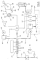
- Figure 5 is a general scheme of the machine control system and of the system for operating the seat raising means.
-
- The machine comprises a movable seat, on which the child sits via a
seating portion 11, in such a manner as to be movably transported with it. This seat preferably has a form which is pleasurable and attractive for the child, for example the form of a vehicle driving seat. - The
seat 10 is carried by amovable structure 20 able to movingly transport a child, and with which mover means for moving thestructure 20 are associated. - In the embodiment shown in the figures, there is provided a
fixed base 15 comprising an annularly extendingrail 16 which rests on the ground. Therail 16 supports amovable base 21 provided with idle wheels which roll along therail 16. While rolling along therail 16, themovable base 21 is constrained to rotate about a vertical axis A by means of avertical pin 22 fixed to the centre of thebase 21 and coupled to abush 17 rigid with thefixed base 15. - The
movable base 21 is connected to mover means for rotating thebase 21 about the axis A. In detail, themovable base 21 carries a gearedmotor 23 which operates asprocket 24 connected by atransmission chain 25 to asprocket 26 of vertical axis fixed to thebush 17. - The
movable base 21 supports saidmovable structure 20 via interposedraising means 40. - Said
raising means 40 are substantially identical to those used in fork lift trucks. Said means 40 comprise a pair ofvertical rails 41 fixed to themovable base 21 at their lower ends and fixed together by ahorizontal cross-member 41a. A verticalrectangular frame 42 is positioned between the tworails 41 and is vertically slidable along theserails 41, to which it is slidingly constrained byidle wheels 42a. The twovertical sides 43 of theframe 42 define two vertical rails, between which there is positioned acarriage 44 slidable vertically along these rails, to which it is slidingly constrained byidle wheels 44a. - The
means 40 also comprise a cylinder-piston unit 45 of vertical axis, having its cylinder fixed to thecross-member 41a, its rod extending upwards and fixed at its upper end to across-member 42b of theframe 42. Atransmission chain 46 is provided having one end fixed to thefixed cross-member 41a and its other end fixed to themovable carriage 44. Thechain 46 passes about anidle sprocket 47 pivoted to theupper cross-member 42c of themovable frame 42. - By virtue of the described mechanism, every movement of the rod of the cylinder-
piston unit 45 produces a corresponding movement of thecarriage 44 but of double the length. Whereas thevertical rails 41 are fixed to theframe 21, themovable structure 20 is fixed to saidcarriage 44, and is hence raised in a vertical direction by the action of the cylinder-piston unit 45. - The
movable structure 20 carries the entiremovable seat 10, which in addition to theseating portion 11 comprises acrank mechanism 30 to be driven by the muscular force of the child. - The
crank mechanism 30 comprises a (double)crank 31 withpedals 32, which is positioned in the front part of theseat 10 in front of theseating portion 11 and is operated by the legs of the child seated on theseating portion 11. The crank mechanism also comprises a pulley wheel 38 (or a chain sprocket) applied to the shaft of thecrank 31, to rotate via a belt 33 (or a chain) a second pulley wheel 34 (or a sprocket) keyed onto asecond shaft 35 carrying a flywheel (not shown in the figures) on which there preferably acts a friction brake. - The described
crank mechanism 30 is arranged to be driven by the muscular force of the child positioned on the movable seat, who rotates the pulley wheel 34 (or other rotary body). - The
seat 10 can advantageously comprise a housing (not shown in the figures) enclosing theseating portion 11, themovable base 21 and the entire crank mechanism, and having a form which imitates a vehicle (or an animal, etc.) to increase the child enjoyment and amusement. For example, in the embodiment shown in the figures, the seat is suitable for enclosure within a housing imitating a helicopter or a similar flying vehicle. For this purpose, there are provided a simulated control device imitating an aircraft control stick positioned in front of theseating portion 11, and a rotatingdisc 14 and rotatingpropeller 13, these being positioned above theseating portion 11, to imitate the rotary members of a helicopter or the like. Advantageously, thepropeller 13 and thedisc 14 are rotated by a mechanical transmission operated by operating thecrank mechanism 30. In this respect, a pair of bevel gears are provided, of which one, 36, is keyed onto theshaft 35 and engages theother gear 37, which is keyed onto a transmission shaft 39 (see Figure 4) housed within avertical column 18 which is rigidly fixed to theseating portion 11 and supports thedisc 14, thepropeller 13 and other transmission shafts and bevel gears (of known type and not further described). - With the cylinder-
piston unit 45 there is associated an operating circuit 50 (shown schematically in Figure 5) comprising apump 51 driven by arelative motor 52 and having its delivery feeding the active chamber 45' of the cylinder-piston unit 45 via aline 53. This chamber is the lower chamber of the cylinder-piston unit 45, its expansion causing the rod of the unit to advance upwards. - In the
line 53 there is provided asolenoid valve 54 arranged to deviate that oil flow directed towards the lower chamber 45' to thesump 55 via a discharge line 54'. In theline 53 there is also asecond valve 56 which enables the oil to pass without throttling when the flow is directed towards the lower chamber 45'. This valve throttles the oil flow during its return from the lower chamber 45'. - According to the invention, the machine comprises a system for controlling the machine movements which inter alia enables one or more characteristics of the seat movement to be varied, in a manner correlated with the speed with which the
crank mechanism 30 is operated by the child seated on theseat 10. - This control system comprises firstly a controlling
microprocessor 61 arranged to control substantially the entire machine operation. It also comprises means connected to themicroprocessor 61 to measure the rotational speed of the wheel 34 (or of another rotary body operated by the crank mechanism 30). Specifically, thewheel 34 comprises holes 34' distributed angularly about the axis of rotation of theshaft 35, a sensor device (encoder) being provided to sense the presence of the holes 34' and feed a consequent signal to themicroprocessor 61. - The
device 62 could instead be applied to another rotary part provided it is rotated by thecrank 31. - In particular, the control system is arranged to act on the
operating circuit 50 for theraising means 40, on the basis of the rotational speed of saidwheel 34, to vary characteristics of the raising movement. In a preferred but not exclusive application, the control system is programmed to act on theoperating circuit 50 in such a manner as to raise themovable seat 10 if the rotational speed of the wheel exceeds a predetermined value, and to lower the movable seat if said speed is less than a predetermined value, or vice versa. - In detail, when during operation the child seated on the
seat 10 operates thecrank 31 with his feet at a speed exceeding the predetermined speed, themicroprocessor 61 calculates this speed on the basis of the signals received from theencoder 62, to act on thevalve 54 so that this closes the line 54' and opens theline 53. The pressurized oil leaving thepump 51 is consequently fed to the chamber of the cylinder-piston unit to raise theseat 10 by the described raising means 40. Thecircuit 50 also comprises an adjustableflow limiting valve 57 which limits the flow rate to the chamber 45'. By adjusting this valve it is hence possible to regulate the speed with which theseat 10 is raised. When theseat 10 has reached its maximum height (corresponding to the maximum emergence of the rod of the cylinder-piston unit 45), it halts in this position and the oil leaving thepump 52 is fed directly to the sump by thesame valve 57. - If instead the
crank 31 is operated at a speed lower than the predetermined speed, themicroprocessor 61 acts on thevalve 54 such that this closes theline 53 and opens thedischarge line 54'. consequently the oil leaving thepump 51 is fed to thesump 55 while theseat 10 descends downwards because of its weight. The fluid present in the chamber 45', being subjected to the pressure caused by the weight of theseat 10 acting on the rod of the cylinder-piston unit 45, is expelled from the chamber 45' (and fed to the sump via the line 54'). This fluid outflow causes the rod of the cylinder-piston unit 45 to descend (together with the seat 10), and is controlled by the throttling produced by thevalve 56, the adjustment of which determines the speed with which theseat 10 is lowered. - In the embodiment shown in the figures, besides rising and descending in a vertical or inclined direction, the
movable seat 10 can also be made to rotate about the axis A, together with the movable base, by the action of the gearedmotor 23. In this case, using an inverter means 63, themicroprocessor 61 is also able to vary the rotational speed of the gearedmotor 23, to consequently vary the speed with which theseat 10 is rotated about the axis A, this being dependent on the speed with which thecrank 31 is operated. - In addition the control system can also be made to rotate the seat for a number of revolutions in one direction then a number of revolutions in the opposite direction.
- Typically, but not exclusively, the machine also comprises a
coin box 64 connected to themicroprocessor 61, and into which the user inserts a coin (or a suitable token) to initiate the ride, and possibly loudspeaker means 65 to increase the enjoyment of the user. - The
microprocessor 61, thesensor device 62, the inverter means 63, the gearedmotor 23 and theentire operating circuit 50 for the cylinder-piston unit 45 are all rotated by themovable base 21. Hence electrical power is fed to themotor 52, to themotor 23 via theinverter 63, and to the microprocessor via a slidingcontact unit 27 comprising a series ofblades 28 which move with themovable base 21 and slide along fixed circular tracks 29 (see Figure 5). - A
power cable 71, connected to the electricity mains, is connected to the fixed tracks 29. Aswitch 72 operated by thecoin box 64 is connected into thecable 71 to close the contact only against payment of a coin. From the contact unit 27 acable 73 powers themicroprocessor 61, anothercable 74 powers theinverter 63 and afurther cable 75 powers themotor 52. - In operation, the user firstly energizes the machine by inserting a coin (or token) into the
coin box 64. After the machine has been energized in this manner, themotor 23 rotates the movable base 21 a few turns in one direction and a few turns in the other, and with it theseat 10. If the child seated on theseat 10 operates thecrank 31 with a speed less than a predetermined value, themicroprocessor 61, which measures this speed on the basis of the signals which it receives from thesensor 62, maintains the rotational speed of themovable base 21 low. Themicroprocessor 61 also acts on thevalve 54 to close theline 53 and open the discharge line 54'. This causes theseat 10 to remain in its lowest position, or to descend into this position. - If instead the rotational speed of the
crank 31 exceeds the predetermined value, themicroprocessor 61 varies the rotational speed of the base 21 by acting on themotor 23 via theinverter 63. Themicroprocessor 61 also acts on thevalve 54 to cause the pressurized oil from thepump 51 to feed the chamber 45', consequently causing theseat 10 to rise by the action of the described raising means 40. - Essentially, if the child pedals quickly, he increases the rotational speed about the axis A of the
seat 10 on which he is seated and causes theseat 10 to rise. In contrast, if he pedals slowly or not at all, theseat 10 returns to its lowest position and the rotational speed decreases. - Numerous modifications can be made to the invention particularly with regard to those movement characteristics of the movable seat which change in relation to the speed with which the crank mechanism is operated by the child. For example, instead of the movable seat being made to move in the vertical direction (as heretofore described) it can be made to move in a different direction eg. forwards and rearwards, including horizontally. Alternatively, instead of being rotated about a vertical axis A, the seat can be rotated about an inclined or horizontal axis, and it can also be made to oscillate in one direction and the other through angles of less than 360°.
- Numerous modifications of a practical and applicational nature can be made to the invention, but without leaving the scope of the inventive idea as hereinafter claimed.
Claims (7)
- An amusement machine comprising at least one movable seat (10) carried by a movable structure (20) arranged to movingly transport a child, and means for moving said structure (10), characterised by comprising, applied to the movable seat (10), a crank mechanism (30) to be operated by the muscular force of the child, and a control system for the machine movements which is able to vary characteristics of the seat movement in a manner correlated with the speed with which the crank mechanism (30) is operated by the child seated on the seat (10).
- An amusement machine as claimed in claim 1, characterised in that said crank mechanism (30) comprises a wheel (14), or another rotary body, which is rotated by the action of the child on the crank mechanism (30), the control system comprising means (62) for measuring the rotation of said wheel (34) or rotary body. and a controlling microprocessor (61) connected to the measurement means (62) to vary characteristics of the movement of the seat (10) in a manner correlated with the speed with which the crank mechanism (30) is rotated.
- An amusement machine as claimed in claim 2, characterised in that the movable seat (10) comprises a pedalled crank (31) which operates said wheel (34), and is operated by the legs of the child carried by the seat.
- An amusement machine as claimed in claim 2, characterised in that said movable seat (10) is raised by raising means (40), the control system being arranged to act on the operating circuit (50) of the raising means (40) on the basis of the rotational speed of said wheel (34), to vary characteristics of the raising movement.
- An amusement machine as claimed in claim 4, characterised in that the control system is arranged to act on the operating circuit (50) of the raising means (40) in such a manner as to raise the movable seat (10) if the rotational speed of said wheel (34) exceeds a predetermined value, and to lower said movable seat (10) if said speed is less than a predetermined value, or vice versa.
- An amusement machine as claimed in claim 5, characterised in that the raising means (40) comprise a hydraulic cylinder-piston unit (45) having an active chamber (45'), said operating circuit (50) of the cylinder-piston unit (45) comprising a pump (51) and a hydraulic circuit which feeds the lower chamber (45') of the cylinder-piston unit and has a solenoid valve (54) operable by the control system to deviate to teh sump that oil flow directed towards the active chamber (45'), and a valve (56) which enables the oil to pass to the lower chamber (45') of the cylinder-piston unit without throttling, but throttles the oil flow returning from the active chamber (45').
- An amusement machine as claimed in claim 4, characterised in that said movable seat (10) is carried by a base (21) rotating about an axis A and connected to drive means (23) which rotate the base (21) about the axis A, the control system being arranged to vary the rotational speed of the movable seat (10) about said axis A in a manner correlated with the speed with which the crank mechanism (30) is operated by the child seated on the seat.
Applications Claiming Priority (3)
| Application Number | Priority Date | Filing Date | Title |
|---|---|---|---|
| ITRE990000 | 1999-03-09 | ||
| IT1999RE000030A IT1310948B1 (en) | 1999-03-09 | 1999-03-09 | FUN MACHINE WITH MOBILE STATION. |
| ITRE990030 | 1999-03-09 |
Publications (3)
| Publication Number | Publication Date |
|---|---|
| EP1034823A2 true EP1034823A2 (en) | 2000-09-13 |
| EP1034823A3 EP1034823A3 (en) | 2001-05-16 |
| EP1034823B1 EP1034823B1 (en) | 2005-07-27 |
Family
ID=11399394
Family Applications (1)
| Application Number | Title | Priority Date | Filing Date |
|---|---|---|---|
| EP00200632A Expired - Lifetime EP1034823B1 (en) | 1999-03-09 | 2000-02-24 | Amusement machine with movable seat |
Country Status (5)
| Country | Link |
|---|---|
| EP (1) | EP1034823B1 (en) |
| AT (1) | ATE300342T1 (en) |
| DE (1) | DE60021453T2 (en) |
| ES (1) | ES2244390T3 (en) |
| IT (1) | IT1310948B1 (en) |
Cited By (3)
| Publication number | Priority date | Publication date | Assignee | Title |
|---|---|---|---|---|
| US8298036B2 (en) | 2006-08-04 | 2012-10-30 | Zen Design Group, Ltd. | Dynamo powered amusement device |
| EP2632794A4 (en) * | 2010-10-26 | 2014-05-07 | Aba Science Play Ltd | Helicopter amusement apparatus |
| WO2016079666A1 (en) | 2014-11-17 | 2016-05-26 | Antonio Zamperla S.P.A. | Vehicle for rotating carousel |
Families Citing this family (1)
| Publication number | Priority date | Publication date | Assignee | Title |
|---|---|---|---|---|
| ITMI20062185A1 (en) * | 2006-11-14 | 2008-05-15 | Zamperla Antonio Spa | FUN ROTARY DEVICE FOR FUN |
Family Cites Families (4)
| Publication number | Priority date | Publication date | Assignee | Title |
|---|---|---|---|---|
| US2896947A (en) * | 1957-02-04 | 1959-07-28 | Jacobs Peter Charles | Captive passenger carrying powered aircraft |
| US3137500A (en) * | 1960-06-27 | 1964-06-16 | Norstan Res & Dev Company | Aviation type amusement device |
| FR2618690B1 (en) * | 1987-07-28 | 1991-02-01 | Roche Jean Jose | ELEVATOR WITH ASCENDING EFFECT |
| US5240417A (en) * | 1991-03-14 | 1993-08-31 | Atari Games Corporation | System and method for bicycle riding simulation |
-
1999
- 1999-03-09 IT IT1999RE000030A patent/IT1310948B1/en active
-
2000
- 2000-02-24 DE DE60021453T patent/DE60021453T2/en not_active Expired - Lifetime
- 2000-02-24 EP EP00200632A patent/EP1034823B1/en not_active Expired - Lifetime
- 2000-02-24 AT AT00200632T patent/ATE300342T1/en not_active IP Right Cessation
- 2000-02-24 ES ES00200632T patent/ES2244390T3/en not_active Expired - Lifetime
Non-Patent Citations (1)
| Title |
|---|
| None |
Cited By (4)
| Publication number | Priority date | Publication date | Assignee | Title |
|---|---|---|---|---|
| US8298036B2 (en) | 2006-08-04 | 2012-10-30 | Zen Design Group, Ltd. | Dynamo powered amusement device |
| EP2632794A4 (en) * | 2010-10-26 | 2014-05-07 | Aba Science Play Ltd | Helicopter amusement apparatus |
| WO2016079666A1 (en) | 2014-11-17 | 2016-05-26 | Antonio Zamperla S.P.A. | Vehicle for rotating carousel |
| US10016690B2 (en) | 2014-11-17 | 2018-07-10 | Antonio Zamperla S.P.A. | Vehicle for rotating carousel |
Also Published As
| Publication number | Publication date |
|---|---|
| ITRE990030A0 (en) | 1999-03-09 |
| EP1034823A3 (en) | 2001-05-16 |
| DE60021453D1 (en) | 2005-09-01 |
| ITRE990030A1 (en) | 2000-09-09 |
| IT1310948B1 (en) | 2002-02-27 |
| EP1034823B1 (en) | 2005-07-27 |
| ATE300342T1 (en) | 2005-08-15 |
| DE60021453T2 (en) | 2005-12-29 |
| ES2244390T3 (en) | 2005-12-16 |
Similar Documents
| Publication | Publication Date | Title |
|---|---|---|
| CA2462989C (en) | Treadmill for performing physical exercise having simplified actuation means | |
| US7604572B2 (en) | Apparatus and method for wheelchair aerobic stationary exercise | |
| US4475613A (en) | Power operated chair | |
| US3981612A (en) | Wave Producing apparatus | |
| US6402626B1 (en) | Bucking machine | |
| US5352167A (en) | Inclination drive mechanism for a treadmill | |
| EP2223722A1 (en) | Adaptive motion exercise device with plural crank assemblies | |
| US20050159278A1 (en) | Variably configured exercise device | |
| EP2208514A2 (en) | Adaptive motion exercise device with oscillating track | |
| US4750565A (en) | Turf aerating apparatus | |
| EP2996971B1 (en) | Linear motion conveyor | |
| US4602687A (en) | Drive mechanism for turf aerating apparatus | |
| NZ204250A (en) | Amusement device:spherical capsule supported by air stream | |
| EP1034823B1 (en) | Amusement machine with movable seat | |
| KR101209384B1 (en) | A height adjustable pitching machine | |
| US4645012A (en) | Turf aerating apparatus | |
| EP2081658A2 (en) | Amusement merry-go-round device | |
| JP2009509628A5 (en) | ||
| KR101197184B1 (en) | Simulator for board sports | |
| KR101050780B1 (en) | 4 degree of freedom ridebot for riding | |
| CN219922018U (en) | A VR device that can rotate freely at multiple angles | |
| US3507222A (en) | Robot ride | |
| KR101064864B1 (en) | Equestrian Motion Drive | |
| US20040147372A1 (en) | Adjustable cushioning apparatus for a treadmill | |
| CN212369524U (en) | Climbing machine |
Legal Events
| Date | Code | Title | Description |
|---|---|---|---|
| PUAI | Public reference made under article 153(3) epc to a published international application that has entered the european phase |
Free format text: ORIGINAL CODE: 0009012 |
|
| AK | Designated contracting states |
Kind code of ref document: A2 Designated state(s): AT BE CH CY DE DK ES FI FR GB GR IE IT LI LU MC NL PT SE |
|
| AX | Request for extension of the european patent |
Free format text: AL;LT;LV;MK;RO;SI |
|
| PUAL | Search report despatched |
Free format text: ORIGINAL CODE: 0009013 |
|
| AK | Designated contracting states |
Kind code of ref document: A3 Designated state(s): AT BE CH CY DE DK ES FI FR GB GR IE IT LI LU MC NL PT SE |
|
| AX | Request for extension of the european patent |
Free format text: AL;LT;LV;MK;RO;SI |
|
| 17P | Request for examination filed |
Effective date: 20011030 |
|
| AKX | Designation fees paid |
Free format text: AT BE CH CY DE DK ES FI FR GB GR IE IT LI LU MC NL PT SE |
|
| AXX | Extension fees paid |
Free format text: AL PAYMENT 20011030;RO PAYMENT 20011030 |
|
| 17Q | First examination report despatched |
Effective date: 20031121 |
|
| GRAP | Despatch of communication of intention to grant a patent |
Free format text: ORIGINAL CODE: EPIDOSNIGR1 |
|
| GRAS | Grant fee paid |
Free format text: ORIGINAL CODE: EPIDOSNIGR3 |
|
| GRAA | (expected) grant |
Free format text: ORIGINAL CODE: 0009210 |
|
| AK | Designated contracting states |
Kind code of ref document: B1 Designated state(s): AT BE CH CY DE DK ES FI FR GB GR IE IT LI LU MC NL PT SE |
|
| AX | Request for extension of the european patent |
Extension state: AL RO |
|
| PG25 | Lapsed in a contracting state [announced via postgrant information from national office to epo] |
Ref country code: CH Free format text: LAPSE BECAUSE OF FAILURE TO SUBMIT A TRANSLATION OF THE DESCRIPTION OR TO PAY THE FEE WITHIN THE PRESCRIBED TIME-LIMIT Effective date: 20050727 Ref country code: BE Free format text: LAPSE BECAUSE OF FAILURE TO SUBMIT A TRANSLATION OF THE DESCRIPTION OR TO PAY THE FEE WITHIN THE PRESCRIBED TIME-LIMIT Effective date: 20050727 Ref country code: NL Free format text: LAPSE BECAUSE OF FAILURE TO SUBMIT A TRANSLATION OF THE DESCRIPTION OR TO PAY THE FEE WITHIN THE PRESCRIBED TIME-LIMIT Effective date: 20050727 Ref country code: AT Free format text: LAPSE BECAUSE OF FAILURE TO SUBMIT A TRANSLATION OF THE DESCRIPTION OR TO PAY THE FEE WITHIN THE PRESCRIBED TIME-LIMIT Effective date: 20050727 Ref country code: LI Free format text: LAPSE BECAUSE OF FAILURE TO SUBMIT A TRANSLATION OF THE DESCRIPTION OR TO PAY THE FEE WITHIN THE PRESCRIBED TIME-LIMIT Effective date: 20050727 Ref country code: FI Free format text: LAPSE BECAUSE OF FAILURE TO SUBMIT A TRANSLATION OF THE DESCRIPTION OR TO PAY THE FEE WITHIN THE PRESCRIBED TIME-LIMIT Effective date: 20050727 |
|
| REG | Reference to a national code |
Ref country code: GB Ref legal event code: FG4D |
|
| REG | Reference to a national code |
Ref country code: CH Ref legal event code: EP |
|
| REG | Reference to a national code |
Ref country code: IE Ref legal event code: FG4D |
|
| REF | Corresponds to: |
Ref document number: 60021453 Country of ref document: DE Date of ref document: 20050901 Kind code of ref document: P |
|
| PG25 | Lapsed in a contracting state [announced via postgrant information from national office to epo] |
Ref country code: SE Free format text: LAPSE BECAUSE OF FAILURE TO SUBMIT A TRANSLATION OF THE DESCRIPTION OR TO PAY THE FEE WITHIN THE PRESCRIBED TIME-LIMIT Effective date: 20051027 Ref country code: DK Free format text: LAPSE BECAUSE OF FAILURE TO SUBMIT A TRANSLATION OF THE DESCRIPTION OR TO PAY THE FEE WITHIN THE PRESCRIBED TIME-LIMIT Effective date: 20051027 Ref country code: GR Free format text: LAPSE BECAUSE OF FAILURE TO SUBMIT A TRANSLATION OF THE DESCRIPTION OR TO PAY THE FEE WITHIN THE PRESCRIBED TIME-LIMIT Effective date: 20051027 |
|
| REG | Reference to a national code |
Ref country code: ES Ref legal event code: FG2A Ref document number: 2244390 Country of ref document: ES Kind code of ref document: T3 |
|
| PG25 | Lapsed in a contracting state [announced via postgrant information from national office to epo] |
Ref country code: PT Free format text: LAPSE BECAUSE OF FAILURE TO SUBMIT A TRANSLATION OF THE DESCRIPTION OR TO PAY THE FEE WITHIN THE PRESCRIBED TIME-LIMIT Effective date: 20051227 |
|
| REG | Reference to a national code |
Ref country code: CH Ref legal event code: PL |
|
| NLV1 | Nl: lapsed or annulled due to failure to fulfill the requirements of art. 29p and 29m of the patents act | ||
| PG25 | Lapsed in a contracting state [announced via postgrant information from national office to epo] |
Ref country code: IE Free format text: LAPSE BECAUSE OF NON-PAYMENT OF DUE FEES Effective date: 20060224 |
|
| PG25 | Lapsed in a contracting state [announced via postgrant information from national office to epo] |
Ref country code: LU Free format text: LAPSE BECAUSE OF NON-PAYMENT OF DUE FEES Effective date: 20060228 Ref country code: MC Free format text: LAPSE BECAUSE OF NON-PAYMENT OF DUE FEES Effective date: 20060228 |
|
| PLBE | No opposition filed within time limit |
Free format text: ORIGINAL CODE: 0009261 |
|
| STAA | Information on the status of an ep patent application or granted ep patent |
Free format text: STATUS: NO OPPOSITION FILED WITHIN TIME LIMIT |
|
| 26N | No opposition filed |
Effective date: 20060428 |
|
| EN | Fr: translation not filed | ||
| PG25 | Lapsed in a contracting state [announced via postgrant information from national office to epo] |
Ref country code: FR Free format text: LAPSE BECAUSE OF FAILURE TO SUBMIT A TRANSLATION OF THE DESCRIPTION OR TO PAY THE FEE WITHIN THE PRESCRIBED TIME-LIMIT Effective date: 20060922 |
|
| REG | Reference to a national code |
Ref country code: IE Ref legal event code: MM4A |
|
| PG25 | Lapsed in a contracting state [announced via postgrant information from national office to epo] |
Ref country code: FR Free format text: LAPSE BECAUSE OF FAILURE TO SUBMIT A TRANSLATION OF THE DESCRIPTION OR TO PAY THE FEE WITHIN THE PRESCRIBED TIME-LIMIT Effective date: 20050727 Ref country code: CY Free format text: LAPSE BECAUSE OF FAILURE TO SUBMIT A TRANSLATION OF THE DESCRIPTION OR TO PAY THE FEE WITHIN THE PRESCRIBED TIME-LIMIT Effective date: 20050727 |
|
| REG | Reference to a national code |
Ref country code: GB Ref legal event code: 732E Free format text: REGISTERED BETWEEN 20091126 AND 20091202 |
|
| REG | Reference to a national code |
Ref country code: ES Ref legal event code: PC2A |
|
| PGFP | Annual fee paid to national office [announced via postgrant information from national office to epo] |
Ref country code: DE Payment date: 20150219 Year of fee payment: 16 |
|
| PGFP | Annual fee paid to national office [announced via postgrant information from national office to epo] |
Ref country code: GB Payment date: 20150218 Year of fee payment: 16 |
|
| REG | Reference to a national code |
Ref country code: DE Ref legal event code: R119 Ref document number: 60021453 Country of ref document: DE |
|
| GBPC | Gb: european patent ceased through non-payment of renewal fee |
Effective date: 20160224 |
|
| PG25 | Lapsed in a contracting state [announced via postgrant information from national office to epo] |
Ref country code: GB Free format text: LAPSE BECAUSE OF NON-PAYMENT OF DUE FEES Effective date: 20160224 Ref country code: DE Free format text: LAPSE BECAUSE OF NON-PAYMENT OF DUE FEES Effective date: 20160901 |
|
| PGFP | Annual fee paid to national office [announced via postgrant information from national office to epo] |
Ref country code: ES Payment date: 20170213 Year of fee payment: 18 Ref country code: IT Payment date: 20170208 Year of fee payment: 18 |
|
| PG25 | Lapsed in a contracting state [announced via postgrant information from national office to epo] |
Ref country code: IT Free format text: LAPSE BECAUSE OF NON-PAYMENT OF DUE FEES Effective date: 20180224 |
|
| REG | Reference to a national code |
Ref country code: ES Ref legal event code: FD2A Effective date: 20190801 |
|
| PG25 | Lapsed in a contracting state [announced via postgrant information from national office to epo] |
Ref country code: ES Free format text: LAPSE BECAUSE OF NON-PAYMENT OF DUE FEES Effective date: 20180225 |