EP1034432B1 - Verfahren und vorrichtung zur bewegungserfassung an mikropartikeln - Google Patents
Verfahren und vorrichtung zur bewegungserfassung an mikropartikeln Download PDFInfo
- Publication number
- EP1034432B1 EP1034432B1 EP98958250A EP98958250A EP1034432B1 EP 1034432 B1 EP1034432 B1 EP 1034432B1 EP 98958250 A EP98958250 A EP 98958250A EP 98958250 A EP98958250 A EP 98958250A EP 1034432 B1 EP1034432 B1 EP 1034432B1
- Authority
- EP
- European Patent Office
- Prior art keywords
- dispenser
- detector
- micro
- coordinates
- particles
- Prior art date
- Legal status (The legal status is an assumption and is not a legal conclusion. Google has not performed a legal analysis and makes no representation as to the accuracy of the status listed.)
- Expired - Lifetime
Links
Images


Classifications
-
- B—PERFORMING OPERATIONS; TRANSPORTING
- B01—PHYSICAL OR CHEMICAL PROCESSES OR APPARATUS IN GENERAL
- B01L—CHEMICAL OR PHYSICAL LABORATORY APPARATUS FOR GENERAL USE
- B01L3/00—Containers or dishes for laboratory use, e.g. laboratory glassware; Droppers
- B01L3/02—Burettes; Pipettes
- B01L3/0241—Drop counters; Drop formers
-
- G—PHYSICS
- G01—MEASURING; TESTING
- G01N—INVESTIGATING OR ANALYSING MATERIALS BY DETERMINING THEIR CHEMICAL OR PHYSICAL PROPERTIES
- G01N35/00—Automatic analysis not limited to methods or materials provided for in any single one of groups G01N1/00 - G01N33/00; Handling materials therefor
- G01N2035/00178—Special arrangements of analysers
- G01N2035/00237—Handling microquantities of analyte, e.g. microvalves, capillary networks
-
- G—PHYSICS
- G01—MEASURING; TESTING
- G01N—INVESTIGATING OR ANALYSING MATERIALS BY DETERMINING THEIR CHEMICAL OR PHYSICAL PROPERTIES
- G01N35/00—Automatic analysis not limited to methods or materials provided for in any single one of groups G01N1/00 - G01N33/00; Handling materials therefor
- G01N35/10—Devices for transferring samples or any liquids to, in, or from, the analysis apparatus, e.g. suction devices, injection devices
- G01N2035/1027—General features of the devices
- G01N2035/1034—Transferring microquantities of liquid
Definitions
- the invention relates to a method for detecting Movement properties of microparticles from a Microdispenser unit can be moved onto a target, in particular a method for recording impact points and speeds of microparticles and a position calibration method for a microdispenser unit with a variety of individual microdispensers.
- the invention also relates to devices for implementing the Method and device for microparticle detection.
- microdispenser it is generally known that the smallest amounts of substance or solution in the form of small solid particles or droplets (microparticles) using a microdispenser on a To place the substrate.
- the microdispenser allows one targeted pipetting of certain volumes and positioning according to certain location coordinates.
- To the successive Placing different substances has one Microdispenser usually has a dispensing head several dispensers for positioning the respective Substances are set up.
- To the substances for example for reaction purposes or to create defined microsubstance grids To be able to position it precisely required the target positions of the dispensed particles to know exactly.
- the position of a dispensing head is usually related manipulable on a target substrate with an actuating device, with which certain head positions can be adjusted.
- the dispensers At Fixed attachment of the individual dispensers of the dispensing head the dispensers have defined reference positions, resulting from the head position and the relative arrangement of the respective dispenser in relation to a reference dispenser result.
- the practical application of dispensing heads shows that at given reference positions the dispenser on the Impact points are formed, their relative coordinates do not correspond to the relative coordinates of the dispensers. This is shown schematically in FIG. 8 using the example of a Dispenser row 30 explained.
- the individual dispensers 30a, 30b, 30c, ... are arranged in a straight row. It can act, for example, micropipettes or the like which micro drops are shot onto a substrate 60.
- the Impact points 61a, 61b, 61c are due to minimal misalignments the dispenser or mechanical instabilities no longer arranged in a straight line, which is special clearly in the lowest part of Fig. 8 by the overlay the dispenser positions and the points of impact are recognizable. This behavior is particularly problematic when a first substance from a first dispenser onto the substrate is moved and after subsequent movement of the dispensing head a second substance from a second dispenser exactly the same substrate position as the first substance should be moved.
- the actuator of the Dispensing head in addition to the dispenser relative positions information about the corresponding impact points relative positions the dispensing head.
- the invention has for its object an improved Process for recording the movement properties of Microparticles, especially from their impact points and / or speeds on target substrates, that has high reliability and is easy to implement is.
- the object of the invention is also a Device for implementing such a method, in particular an improved microparticle detector device, specify.
- the relative coordinates of the impact points and / or their Deviation from the relative coordinates of the dispenser positions detected with a particle detector device the two each linearly limited interaction areas spanning a target level has and for emitting a detector signal is set up as soon as a microparticle in one of the Areas of interaction occurs.
- Reference dispenser coordinates each at the actuating device set dispensing head coordinates.
- the dispensing head is then opened during a measuring step a measuring path that corresponds to one of the calibration paths or runs parallel to one of them over which Detector device driven so that each time it is reached one of the interaction areas of one of the other dispensers (Measuring dispenser) emits a sequence of microparticles.
- the dispenser position becomes relative the position of the dispensing head and the point of impact determined on the interaction area.
- the microparticle speed capture it is possible to in addition to the movement parameters mentioned above, the microparticle speed capture.
- a device is according to a first Point of view by said detector device with two linearly limited interaction areas spanning a target level educated.
- the measuring principle is the detector device as an electroacoustic Sensor or designed as an electro-optical sensor.
- each of the other non-parallel interaction areas through a vibration element formed that at least one straight boundary has when reached by a microparticle the sequences of Microparticles in the vibration element a mechanical Vibration is triggered.
- the mechanical vibration is with converted into a detector signal by a suitable sound transducer, which indicates suitable signal processing, which of the interaction areas of a microparticle was hit.
- the vibration element preferably has the Form of a tensioned elastic thread with a Membrane of a microphone is connected, which acts as a transducer acts.
- the detector device has two just spanned at a predetermined angle ( ⁇ 0) aligned threads, preferably of metal, which are the target plane span and connected to a microphone are.
- ⁇ 0 predetermined angle aligned threads, preferably of metal, which are the target plane span and connected to a microphone are.
- an apparatus from a combination of the above Detector device with a signal processing circuit and a position sensor with an actuating device Interacting dispensing head.
- a combination of the above Detector device with a signal processing circuit and a position sensor with an actuating device Interacting dispensing head is advantageously for the calibration of the impact points of a Group of dispensers of a dispensing head can be used.
- the invention has the advantage that the points of impact a dispensing head or a corresponding microparticle placement device fully automated, fast and reliable can be determined.
- the position is determined with a simply built detector while avoiding conventional ones Image recognition method.
- the advantages of the invention also in immunity, speed, accuracy and the relatively low cost of the detector.
- the invention is based on the example of a horizontal manipulable dispensing head with a linear dispenser arrangement, for example by a group of piezoelectric working micropipettes is formed to Apply microscopic droplets to a substrate described.
- the invention is not based on such Micropipette arrangement with vertical drop movement limited, but correspondingly with all types of microparticle placement devices applicable, which is also two-dimensional Wear dispenser assemblies or for particle movement set up with horizontal motion components could be.
- a microparticle is therefore a liquid drop or solid body with a characteristic size, which in the Submillimeter range (visible up to the wavelength Light) is enough.
- the invention is also described with reference to the embodiment of the detector device as electroacoustic Sensor described. The corresponding process steps calibration, impact point determination, dispensing head positioning, Signal evaluation etc. are however in the case of an electro-optical sensor without restriction applicable.
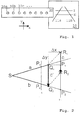
- Fig. 1 shows schematically the relative orientation of a Dispensing head 30 and a detector device 10 in Top view.
- the dispensing head 30 is in the drawing plane in movable in the x and y directions.
- the x and y directions span a plane parallel to that of the detector wires 11a, 11b spanned target level.
- the dispensing head 30 several times along at least two straight, parallel, spaced-apart routes I, II, their vertical Projections onto the target plane the detector wires 11a, 11b cut, passed over the detector device.
- the Dispensing head is equipped with an actuator (see below) actuated, which is connected to a position transmitter (see below) is.
- the position encoder supplies coordinates in an environment coordinate system, the reference for everyone in the following represents the specified locations. These include the current ones Dispensing head coordinates, which for simplification with the Coordinates of a reference dispenser (e.g. dispenser 30a) be equated.
- the coordinates of the other dispensers (Measuring dispensers 30b, 30c, ...) result from the dispensing head coordinates and the known, measurable coordinates the measuring dispenser relative to the reference dispenser.
- the reference dispenser coordinates are detected at the dispensing head positions at which a microdrop emanating from the reference dispenser hits one of the detector wires 11a, 11b.
- the dispensing head is first aligned with the travel distance I and is driven over it via the detector device.
- the detector wires 11a, 11b are run over at a constant driving speed and constant drop delivery rate.
- the driving speed, the frequency, the drop diameter and the dispenser-wire distance are selected in a suitable manner depending on the respective application and the dimensions of the detector device.
- the frequency in relation to the driving speed is selected such that the number of drops per unit length is significantly less than the spatial resolution of the actuating device of the dispensing head.
- the drop delivery rate or frequency approx. 500 drops per second, the drop diameter approx. 50 to 60 ⁇ m and the dispenser wire distance approx. 2-3 mm.
- the microdroplets are passed over, it is hit by the microdroplets.
- the first streak of a microdroplet causes a deflection of the detector wire and the generation of a detector signal (described below) on which the current reference dispenser coordinates are stored.
- the storage takes place with simultaneous check whether there was an interference signal. If this is the case, the detector signal is discarded.
- the dispensing head 30 is moved on to the second detector wire 11b for detecting the reference dispenser coordinates in accordance with the point P 2 .
- the same sequence then takes place along the parallel, spaced-apart travel route II.
- the distance between the travel routes I, II is selected to achieve sufficient measuring accuracy and can, for example, approx. 1 to 3 cm.
- the impact points of microdroplets are determined from each of the other measuring pipettes 30b, 30c In the first calibration steps, depending on the substance, contamination of the detector wires is expected along these routes, traveled along a third, parallel route via the detector device 10.
- the more or simple passing over of the detector device can be combined with a simultaneous adjustment of the dispensing head perpendicular to the direction of travel, so that the detector wire is hit by a microdrop at a different point.
- the points of impact of microdroplets from measuring dispensers are referred to below as Q 1 , Q 2 .
- the impact points Q 1 , Q 2 of the microdrops from the measuring dispensers are calculated as follows (see FIG. 2).
- the straight line equations of the detector wires are determined from the reference dispenser coordinates for the reference impact points P 1 , P 3 and P 2 , P 4, respectively.
- the coordinates of the (imaginary) intersection S of the two detector wires are then determined from the straight line equations.
- result from the ray set as follows:
- (
- (
- the coordinates of the points Q 1 , Q 2 determined in this way relate to the above-mentioned coordinate system of the position transmitter.
- the deviation of these coordinates ⁇ x ⁇ y from the coordinates of the measuring dispenser R 1 , R 2 represents the desired deviation of the point of impact from the position of the measuring dispenser.
- These deviation coordinates can be used within the scope of a dispensing head calibration in order to reproducibly record the points of impact of each dispenser of a dispensing head or in order to correct the position of a dispensing head during operation to implement a specific dispensing position in relation to a desired substrate impact point.
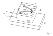
- the detector device 10 comprises two detector sections 110a, 110b, which are mounted on a support block 120 are.
- the carrier block 120 also carries a protective cover 130, which is the top of the support block 120 except for the Detector sections 110a, 110b covered.
- the protective cover 130 which releases the detector sections 110a, 110b can be alternatively provided that on the top of the support block 120 recesses made (milled) into which the parts of the detector sections 110a, 110b are let in. This will protect the detector wires against mechanical influences and sound shielding achieved against background noise.
- the detector sections 110a, 110b each have a microphone (see FIG. 4) which is connected via Connection lines 140 with the signal processing circuit 200 (s. Fig. 5) is connected.
- the support block 120 and the protective cover 130 are preferably made of a solid plastic material (e.g. plexiglass).
- the height of the support block 120 (With a support plate 121 which may be provided) can be selected in this way be that the height of the detector sections 110a, 110b about the Height of a substrate to be loaded in relation to one Dispensing head that is to be examined.
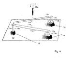
- the detector sections 110a, 110b are (without the Carrier block and the protective cover) shown in Fig. 4.
- the Detector sections 110a, 110b each comprise a detector wire (or drip catcher wire) 11a, 11b, which is vibrationally coupled is connected to a microphone 13a, 13b.
- everyone Detector wire 11a, 11b is aligned.
- This is one clamping device 14a, 15a, 14b, 15b each is provided, the one clamping bracket 14a, 14b and a carrier element 15a, 15b includes.
- Each clamping bracket 14a, 14b is by the respective Support element 15a, 15b aligned so that the clamped Detector wires 11a, 11b to each other at a predetermined angle (preferably ⁇ 90 °, e.g. around 45 °, and thereby one Spanning the detector target level.
- a predetermined angle preferably ⁇ 90 °, e.g. around 45 °, and thereby one Spanning the detector target level.
- the detector target level parallel to the x-y plane of the actuating device (not a dispensing head with the dispenser 30a.
- the ends of the detector wires 11a, 11b are each at the Ends of the clamps 14a, 14b clamped. There is a Preload in such a way that in the expected operating temperature range each detector wire is stretched so far that it is between the Clamping bracket ends straight.
- Each detector wire forms an interaction area mentioned above. By in in this case linear shape of the interaction area this has a straight limitation on all sides.
- a vibration element a vibration membrane to be used to implement the evaluation principle explained above a straight limit in terms of Formation of the impinging sequence of drops must have.
- the detector wires 11a, 11b consist of an elastic, vibratable material. It is preferably about Wires made of metals with a high sound conductivity, such as e.g. Copper, so that the positioning of the microphone in relation on the detector wire is not a problem.
- a high sound conductivity such as e.g. Copper
- Each detector coupling element 12a, 12b is with the respective microphone, preferably with the respective microphone membrane.
- the detector wires 11a, 11b have a diameter of approx. 40 ⁇ m. Generally the diameter of each detector wire is selected so that on the one hand the sound insulation is sufficiently low and on the other hand the wire stability is sufficiently high.
- the clamp diameter is approx. 0.9 mm.
- the elements of the detector sections 110a, 110b are over sound-absorbing mounts with the support block 120 (see FIG. 3) connected.
- the sound-absorbing mounts are, for example made of foam padding 16 or comparable Attenuators.
- For the carrier elements 15a, 15b a common bracket is provided. It is possible to do both Clamping bracket 14a, 14b on a common carrier element Fasten.
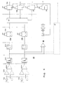
- Fig. 5 shows schematically the combination of the described Detector device 10 with a dispensing head 30 for Formation of a calibration device for the dispensing head.
- the Detector device 10 is with a signal processing circuit 20 connected to derive digital control signals set up from the detector signals of the detector device 10 and its details below with reference to Fig. 6 are described.
- the digital control signals are on a control device 50 given, for example, by a computer with two digital inputs and one digital output is formed.
- the control device 50 delivers Signals to the (x-y-z) actuator 40 with the position transmitter 41, with which the dispensing head 30 in the x-y plane parallel to the detector target plane and perpendicular to it in one z direction is movable.
- the dispensing head 30 exists for example from a plurality of rows arranged Pipettes 30a, 30b, 30c ...., which, when used as intended Use are loaded with various substances.
- the signal processing circuit 20 includes, as shown in FIG. 6, for everyone the signal converter (e.g. microphones 13a, 13b) of the detector device one digital signal channel 21a, 21b, and one each Logic circuit 22, an error display 23, hit signal circuits 24a, 24b, a reset circuit 25 and an audio device 26.
- a sound detection circuit 27 (such as RSC-164 by Sensory Inc., USA) may be provided for further Control during signal evaluation by providing a Signal on detection of a drop noise is set up.
- the digital signal channel 21a (and accordingly the second Digital signal channel 21b) contains a preamplifier 211, one Bandpass 212, a rectifier 213 and an extension circuit 214.
- the preamplifier 211 the detector signal preamplified by the microphone 13a.
- the band pass 212 the expected drop frequency spectrum is filtered out.
- Fig. 7a has a vibrating detector wire a characteristic after hitting a microdroplet Spectrum, whose frequency focus at approx. 3.5 kHz lies and on which the bandpass 212 is set up. After this The filtered detector signal has a bandpass in the form of a curve 7b (upper curve).
- the filtered detector signal becomes a rectification to form a signal with TTL level (TTL pulse) subjected to rectifier 213.
- TTL pulse TTL level
- the rectified signal has the form shown in FIG. 7b (lower Curve).
- the TTL pulse from the ⁇ sin converted the ms range.
- the concern of the extended Impulse is indicated with an LED.
- the logic circuit 22 is for the exclusion of error signals intended. If on the digital signal channels 21a, 21b TTL pulses are triggered at the same time, this means that the detector signal is not due to the impact of a Drop, but through one of the two detector wires at the same time relevant disturbance event was triggered. In this case, is on the error display 23 made a display and a Error signal to the control device 50 (see FIG. 5). If a TTL pulse is detected either on the channel during drop detection 21a or on channel 21b, then the corresponding Signal passed to one of the hit signal circuits 24a, 24b, each with an LED to indicate whether the first or second detector wire was hit. The hit signal circles 24a, 24b in turn serve to extend the display time, to enable visual observation by the operator. The digital signals from the hit signal circles are each passed to the control device 50 which is with the axis control system (Control device 40, position transmitter 41 s. Fig. 5) is connected.
- the signal processing circuit 20 also includes the reset circuit 25, on the one hand at the beginning of the measurement with a Control signal reset (e.g. to "High” or “Active”) can and after correct signal detection by the control device 50 receives a reset signal. This will also given to the hit signal circuits 24a, 24b.
- a Control signal reset e.g. to "High” or “Active”
- the audio device 26 is used to make the Drop noise. It contains an NF amplifier downstream loudspeaker whose response depends on the state a reset switch that runs with the reset circuit 25 is connected.
- an additional sound converter for each digital signal channel 215 and a preamplifier 216 may be provided, the Output signal together with the output signal of the preamplifier 211 a differential amplification at the differential amplifier 217 is subjected, whose output signal at bandpass 212 is applied.
- These additional circuit components are preferred when operating the detector device in an environment provided with a high noise level. The noise level will continuously recorded with an additional microphone and through the Differential amplifier with the useful signal from the microphone 13a Compared detector.
- the control device 50 is in addition to the processing of the Digital signals from the signal processing circuit 20 for calculation the deviation coordinates as explained above, and to provide correction signals to the position encoder 41 for functional use of the dispensing head 30 for Feeding a substrate set up.
- These correction signals advantageously allow the dispensing head 30 can be manipulated so that microdrops from each the micropipettes 30a, 30b, 30c, .... with high accuracy (Error ⁇ 10 ... 20 ⁇ m) to a predetermined substrate position can be shot. This ensures that the location accuracy the microparticle placement of any that occur Misalignments of the individual dispensers become independent and only from the accuracy of the position setting of the Actuator is dependent.
- the signal processing circuit 20 can additionally provided with a signal evaluation circuit (not shown) be used to determine the drop speed Detector signals is set up.
- a signal evaluation circuit (not shown) be used to determine the drop speed Detector signals is set up.
- the Speed of microparticles corresponding to one of the following procedures.
- the detector device According to a first Possibility of multiple bombardment of a detector section the detector device with a constant x-y dispensing head position, but always off different heights (z-direction) in relation to the respective Detector section. Depending on the height, this occurs for to differentiate the hit characteristic TTL signal Points in time. From the time differences of the arrival times and the corresponding height differences is assumed the speed of an acceleration-free movement calculated.
- piezoelectric when used working micropipettes an electric Trigger pulse for the piezoelectric encoder as a start pulse and the impact TTL signal as a final pulse for a time measurement to use, again the speed from the Ratio of the measurable flight distance to the measured start-end time results.
- the start pulse from derive the respective sound transducer. For example, at a microphone the means for electromagnetic shielding away, the microphone speaks to an electromagnetic one Pulse on which when the trigger pulse is applied from piezoelectric encoder is emitted.
Landscapes
- Health & Medical Sciences (AREA)
- Clinical Laboratory Science (AREA)
- Chemical & Material Sciences (AREA)
- Chemical Kinetics & Catalysis (AREA)
- Automatic Analysis And Handling Materials Therefor (AREA)
- Length Measuring Devices By Optical Means (AREA)
Description
- Fig. 1:
- eine schematische Draufsicht auf einen Dispensierkopf und eine Detektorvorrichtung zur Illustration des erfindungsgemäßen Verfahrens;
- Fig. 2:
- eine geometrische Darstellung zur Illustration des Auswertungsschemas gemäß der Erfindung;
- Fig. 3:
- eine Perspektivansicht einer Detektorvorrichtung gemäß der Erfindung;
- Fig. 4:
- eine Perspektivansicht von Einzelheiten einer Detektorvorrichtung gemäß Fig. 3;
- Fig. 5:
- eine schematische Blockdarstellung einer erfindungsgemäßen Kombination der Detektorvorrichtung mit der Stelleinrichtung eines Dispensierkopfes;
- Fig. 6:
- eine Blockdarstellung einer Signalverarbeitungsschaltung aus Fig. 5;
- Fign. 7A, B:
- Kurvendarstellungen zur Illustration von Signalverläufen der Detektorvorrichtung; und
- Fig. 8:
- eine Schemadarstellung der Abweichung zwischen Relativdispenserkoordinaten und Relativauftreffpunktkoordinaten.
Claims (14)
- Verfahren zur Erfassung der Auftreffpunkte von Mikropartikeln, die sich von mehreren Dispensern (30a, 30b, 30c, ...) einer Dispenserreihe (30) zu einem Träger (120) bewegen, mit den Schritten:Verfahren des Dispensierkopfes unter Abgabe einer Folge von Mikropartikeln aus einem Referenzdispenser (30a) über einer Detektorvorrichtung auf dem Träger (120) mit zwei linear begrenzten, elektroakustischen oder elektrooptischen Wechselwirkungsbereichen, die eine Targetebene aufspannen, entlang mindestens zweier, gerader paralleler Fahrstrecken (I, II),Ermitteln der Referenzdispenserkoordinaten (P1, P2) für die Dispensierkopfpositionen, in denen Mikropartikel auf die Wechselwirkungsbereiche treffen,Verfahren des Dispensierkopfes unter Abgabe einer Folge von Mikropartikeln aus mindestens einem Meßdispenser (30b, 30c ...) parallel zu den Fahrstrecken (I, II), undErmitteln von Auftreffpunktkoordinaten (Q1, Q2) für die Dispensierkopfpositionen, in denen Mikropartikel aus dem Meßdispenser auf die Wechselwirkungsbereiche treffen.
- Verfahren gemäß Anspruch 1, bei dem aus den Auftreffpunktkoordinaten (Q1, Q2), den Koordinaten des Dispensierkopfes und den Relativkoordinaten der Meßdispensern am Dispensierkopf Abweichungskoordinaten (Δx, Δy) zwischen den Auftreffpunktkoordinaten und den Meßdispenserkoordinaten ermittelt werden.
- Verfahren gemäß Anspruch 2, bei dem aus den Abweichungskoordinaten Korrektursignale für einen Positionsgeber des Dispensierkopfes zur Einstellung von Dispensern zur Bewegung der Mikropartikel auf vorbestimmte Substratpositionen ermittelt werden.
- Verfahren gemäß Anspruch 3, bei dem auf der Grundlage der Abweichungskoordinaten die Dispenserkoordinaten des Dispensierkopfes kalibriert werden.
- Verfahren gemäß einem der vorhergehenden Ansprüche, bei dem das Auftreffen eines Mikropartikels auf einen der Wechselwirkungsbereiche durch Ermittlung eines Detektorsignals erfaßt wird, das in ein Digitalsignal umgewandelt wird, dessen Anstiegsflanke für den Zeitpunkt des Auftreffens des Mikropartikels charakteristisch ist.
- Verfahren zur Erfassung der Geschwindigkeit von Mikropartikeln, die sich von mehreren Dispensern (30a, 30b, 30c, ...) einer Dispenserreihe (30) zu einem Träger (120) bewegen, mit den Schritten:Positionieren des Dispensierkopfes über einer Detektorvorrichtung mit zwei linear begrenzten, elektroakustischen oder elektrooptischen Wechselwirkungsbereichen, die eine Targetebene aufspannen, derart, daß Mikropartikel aus einem der Dispenser auf einen der Wechselwirkungsbereiche treffen,Ermitteln der Mikropartikelgeschwindigkeit aus Wegabschnitten, die die Mikropartikel auf dem Weg vom Dispenser zum Wechselwirkungsbereich durchlaufen, und den zugehörigen zum Durchlaufen der Wegabschnitte erforderlichen Zeitabschnitte.
- Verfahren gemäß Anspruch 6, bei dem der Wegabschnitt der Abstand vom Dispenser zum Wechselwirkungsbereich ist und der zugehörige Zeitabschnitt aus einem Auslösesignal des Dispensers und einem Detektorauftreffsignal der Detektorvorrichtung abgeleitet wird.
- Verfahren gemäß Anspruch 6, bei dem Mikropartikel bei verschiedenen Dispenser-Wechselwirkungsbereich-Abständen abgegeben werden, deren Differenz den Wegabschnitt für die Geschwindigkeitsmessung bildet, wobei der Zeitabschnitt aus den Detektorauftreffsignalen für die verschiedenen Dispenserabstände abgeleitet wird.
- Verfahren gemäß Anspruch 6, das mit einem Verfahren gemäß einem der Ansprüche 1 bis 5 kombiniert wird, um die Position und Geschwindigkeit von Mikropartikeln aus den Dispensern zu kalibrieren.
- Detektorvorrichtung zur Erfassung der Auftreffpunkte oder Geschwindigkeit von Mikropartikeln, die von mehreren Dispensern (30a, 30b, 30c, ...) einer Dispenserreihe (30) abgegeben werden, mit zwei linear begrenzten, elektroakustischen oder elektrooptischen Wechselwirkungsbereichen, die unter Bildung eines vorbestimmten Winkels zueinander angeordnet sind und eine Targetebene aufspannen, wobei jeder Wechselwirkungsbereich dazu eingerichtet ist, ein Detektorsignal abzugeben, wenn ein Mikropartikel auf den Wechselwirkungsbereich trifft.
- Detektorvorrichtung gemäß Anspruch 10, bei der jeder Wechselwirkungsbereich einen elektroakustischen Detektorabschnitt (110a, 110b) mit einem Schwingungselement aufweist, das mit einem Schallwandler schwingungsgekoppelt ist.
- Detektorvorrichtung gemäß Anspruch 11, bei der das Schwingungselement ein Detektordraht (11a, 11b) und der Schallwandler ein Mikrophon (13a, 13b) ist.
- Detektorvorrichtung gemäß Anspruch 10, bei der jeder Wechselwirkungsbereich einen elektrooptischen Detektorabschnitt aufweist, der von einem geraden, parallelen Lichtstrahl durchsetzt wird und mindestens ein Photoelement aufweist.
- Kalibrierungseinrichtung für einen Dispensierkopf (30) mit einer Vielzahl von Dispensern (30a, 30b, 30c....), umfassend eine Detektorvorrichtung gemäß einem der Ansprüche 10 bis 13, einen Signalverarbeitungskreis (20) und eine Steuereinrichtung (50), die zur Erfassung von Dispensierkopfkoordinaten zu den Zeitpunkten eingerichtet ist, wenn Mikropartikel aus Dispensern auf die Wechselwirkungsbereiche treffen.
Applications Claiming Priority (3)
| Application Number | Priority Date | Filing Date | Title |
|---|---|---|---|
| DE19752010A DE19752010C1 (de) | 1997-11-24 | 1997-11-24 | Verfahren und Vorrichtung zur Erfassung von Mikropartikeln |
| DE19752010 | 1997-11-24 | ||
| PCT/EP1998/007558 WO1999027372A1 (de) | 1997-11-24 | 1998-11-23 | Verfahren und vorrichtung zur bewegungserfassung an mikropartikeln |
Publications (2)
| Publication Number | Publication Date |
|---|---|
| EP1034432A1 EP1034432A1 (de) | 2000-09-13 |
| EP1034432B1 true EP1034432B1 (de) | 2003-08-06 |
Family
ID=7849654
Family Applications (1)
| Application Number | Title | Priority Date | Filing Date |
|---|---|---|---|
| EP98958250A Expired - Lifetime EP1034432B1 (de) | 1997-11-24 | 1998-11-23 | Verfahren und vorrichtung zur bewegungserfassung an mikropartikeln |
Country Status (4)
| Country | Link |
|---|---|
| US (1) | US6467328B1 (de) |
| EP (1) | EP1034432B1 (de) |
| DE (2) | DE19752010C1 (de) |
| WO (1) | WO1999027372A1 (de) |
Families Citing this family (7)
| Publication number | Priority date | Publication date | Assignee | Title |
|---|---|---|---|---|
| DE10000608C2 (de) | 2000-01-10 | 2002-05-23 | Max Planck Gesellschaft | Verfahren und Vorrichtung zur Erfassung der relativen Auftreffpositionen von Mikropartikeln |
| US6726318B2 (en) * | 2001-11-30 | 2004-04-27 | Konica Corporation | Microscopic droplet detecting device and ink-jet recording apparatus |
| DE102005010847B4 (de) * | 2005-03-07 | 2007-08-02 | Rea Elektronik Gmbh | Vorrichtung zur Messung einer austretenden Flüssigkeit |
| CN101277759A (zh) * | 2005-10-07 | 2008-10-01 | 皇家飞利浦电子股份有限公司 | 用于将物质的液滴受控地放置在基板上的喷墨设备,用于受控地放置物质的液滴的方法以及喷墨设备的使用 |
| FR3009881B1 (fr) * | 2013-08-23 | 2017-03-17 | Stmi Soc Des Techniques En Milieu Ionisant | Modelisation 3d topographique et radiologique d'un environnement |
| CN106861980A (zh) * | 2015-12-14 | 2017-06-20 | 北汽福田汽车股份有限公司 | 一种涂装机器人转速反馈系统及一种涂装机器人 |
| CN115079133B (zh) * | 2022-06-14 | 2023-05-12 | 山东沂蒙地理信息有限公司 | 一种基于激光测距技术的校准测距仪及其运行方法 |
Family Cites Families (4)
| Publication number | Priority date | Publication date | Assignee | Title |
|---|---|---|---|---|
| CH668130A5 (en) * | 1987-01-23 | 1988-11-30 | Volpi Ag | Light barrier for measuring speed of object - detects object between source and receiver from shading of receiver and contains circular to rectangular cross-sectional converters |
| US5508200A (en) | 1992-10-19 | 1996-04-16 | Tiffany; Thomas | Method and apparatus for conducting multiple chemical assays |
| EP0601213A1 (de) | 1992-10-29 | 1994-06-15 | Hamilton Bonaduz AG | Vorrichtung zum Transportieren von Waren |
| US5847722A (en) | 1995-11-21 | 1998-12-08 | Hewlett-Packard Company | Inkjet printhead alignment via measurement and entry |
-
1997
- 1997-11-24 DE DE19752010A patent/DE19752010C1/de not_active Expired - Fee Related
-
1998
- 1998-11-23 DE DE59809232T patent/DE59809232D1/de not_active Expired - Fee Related
- 1998-11-23 WO PCT/EP1998/007558 patent/WO1999027372A1/de not_active Ceased
- 1998-11-23 EP EP98958250A patent/EP1034432B1/de not_active Expired - Lifetime
- 1998-11-23 US US09/555,068 patent/US6467328B1/en not_active Expired - Fee Related
Also Published As
| Publication number | Publication date |
|---|---|
| DE59809232D1 (de) | 2003-09-11 |
| EP1034432A1 (de) | 2000-09-13 |
| US6467328B1 (en) | 2002-10-22 |
| WO1999027372A1 (de) | 1999-06-03 |
| DE19752010C1 (de) | 1999-08-19 |
Similar Documents
| Publication | Publication Date | Title |
|---|---|---|
| DE102017214574B4 (de) | Lichtsensor | |
| DE102008049821B4 (de) | Abstandssensor und Verfahren zur Ermittlung eines Abstands und/oder von Abstandsschwankungen zwischen einem Bearbeitungslaser und einem Werkstück | |
| DE19544299C2 (de) | Verfahren und Vorrichtung zum Vermessen von Strukturen | |
| EP2767964B1 (de) | Vorrichtung zur Fahrzeugvermessung | |
| EP3990887A1 (de) | Sensoranordnung zur charakterisierung von partikeln | |
| EP0565090A1 (de) | Verfahren und Vorrichtung zur Messung der Abmessung eines Objekts | |
| EP4150370B1 (de) | Verfahren zum kalibrieren und/oder justieren und steuereinheit für ein lidar-system, lidar-system und arbeitsvorrichtung | |
| EP3404441A1 (de) | Simulationsvorrichtung für ein lidar-lichtmesssystem | |
| DE19752010C1 (de) | Verfahren und Vorrichtung zur Erfassung von Mikropartikeln | |
| DE102013102659B4 (de) | Proben-Vorbereitungseinrichtung und Proben-Vorbereitungsverfahren | |
| DE19802848A1 (de) | Verfahren und Vorrichtung zum Testen eines Substrats | |
| WO2016180906A1 (de) | Vorrichtung und verfahren zur ermittlung der anzahl an feststoffpartikeln in einem fluidstrom | |
| DE102015007506B3 (de) | Vorrichtung und Verfahren zur Bestimmung einer Partikelgröße in einem Sprühstrahl | |
| DE102018215177B4 (de) | Autofokus- und Partikelsensorvorrichtung und entsprechendes Verfahren, sowie Kamera- und Partikelsensorsystem | |
| DE10000608C2 (de) | Verfahren und Vorrichtung zur Erfassung der relativen Auftreffpositionen von Mikropartikeln | |
| EP1038184B1 (de) | Vorrichtung und verfahren zur bildaufnahme an tropfenerzeugenden dispensierköpfen | |
| EP2735887A1 (de) | Optische Erfassungsvorrichtung | |
| EP1520165B1 (de) | Verfahren und vorrichtung zur durchführung der emissionsspektrometrie | |
| DE102023107515B4 (de) | Vorrichtung und Verfahren zur Erfassung mindestens eines Tropfens | |
| DE10313141A1 (de) | Verfahren und Einrichtung für die Bestimmung der vektoriellen Distanz zwischen der Kapillare und dem Bilderkennungssystem eines Wire Bonders | |
| DE102019008685B4 (de) | Optische Messanordnung und Verfahren zur Präsenzerkennung kleiner Objekte in einem Strahlengang | |
| EP2928280A2 (de) | Messmarkensystem zur Kalibrierung einer Maschine | |
| DE102007027253A1 (de) | Verfahren und Vorrichtung zum Ermitteln der Bodenfreiheit eines Fahrzeugs | |
| WO2025131730A1 (de) | Vorrichtung und verfahren zur charakterisierung mindestens eines partikels | |
| EP1726913A1 (de) | Sensor und Sensorsystem zur optischen Erfassung von Objekten, Bestückkopf, Verfahren zur Bestimmung der Höhensposition eines Bauelements |
Legal Events
| Date | Code | Title | Description |
|---|---|---|---|
| PUAI | Public reference made under article 153(3) epc to a published international application that has entered the european phase |
Free format text: ORIGINAL CODE: 0009012 |
|
| 17P | Request for examination filed |
Effective date: 20000517 |
|
| AK | Designated contracting states |
Kind code of ref document: A1 Designated state(s): CH DE GB LI |
|
| GRAH | Despatch of communication of intention to grant a patent |
Free format text: ORIGINAL CODE: EPIDOS IGRA |
|
| GRAH | Despatch of communication of intention to grant a patent |
Free format text: ORIGINAL CODE: EPIDOS IGRA |
|
| GRAA | (expected) grant |
Free format text: ORIGINAL CODE: 0009210 |
|
| AK | Designated contracting states |
Designated state(s): CH DE GB LI |
|
| REG | Reference to a national code |
Ref country code: GB Ref legal event code: FG4D Free format text: NOT ENGLISH |
|
| REG | Reference to a national code |
Ref country code: CH Ref legal event code: EP |
|
| REF | Corresponds to: |
Ref document number: 59809232 Country of ref document: DE Date of ref document: 20030911 Kind code of ref document: P |
|
| REG | Reference to a national code |
Ref country code: CH Ref legal event code: NV Representative=s name: PFEIFFER VACUUM (SCHWEIZ) AG |
|
| GBT | Gb: translation of ep patent filed (gb section 77(6)(a)/1977) |
Effective date: 20031027 |
|
| PG25 | Lapsed in a contracting state [announced via postgrant information from national office to epo] |
Ref country code: GB Free format text: LAPSE BECAUSE OF NON-PAYMENT OF DUE FEES Effective date: 20031123 |
|
| PG25 | Lapsed in a contracting state [announced via postgrant information from national office to epo] |
Ref country code: LI Free format text: LAPSE BECAUSE OF NON-PAYMENT OF DUE FEES Effective date: 20031130 Ref country code: CH Free format text: LAPSE BECAUSE OF NON-PAYMENT OF DUE FEES Effective date: 20031130 |
|
| PG25 | Lapsed in a contracting state [announced via postgrant information from national office to epo] |
Ref country code: DE Free format text: LAPSE BECAUSE OF NON-PAYMENT OF DUE FEES Effective date: 20040602 |
|
| PLBE | No opposition filed within time limit |
Free format text: ORIGINAL CODE: 0009261 |
|
| STAA | Information on the status of an ep patent application or granted ep patent |
Free format text: STATUS: NO OPPOSITION FILED WITHIN TIME LIMIT |
|
| GBPC | Gb: european patent ceased through non-payment of renewal fee |
Effective date: 20031123 |
|
| REG | Reference to a national code |
Ref country code: CH Ref legal event code: PL |
|
| 26N | No opposition filed |
Effective date: 20040507 |