EP1033700A2 - Locking fastener for a strap - Google Patents
Locking fastener for a strap Download PDFInfo
- Publication number
- EP1033700A2 EP1033700A2 EP00400398A EP00400398A EP1033700A2 EP 1033700 A2 EP1033700 A2 EP 1033700A2 EP 00400398 A EP00400398 A EP 00400398A EP 00400398 A EP00400398 A EP 00400398A EP 1033700 A2 EP1033700 A2 EP 1033700A2
- Authority
- EP
- European Patent Office
- Prior art keywords
- fastener
- strap
- aperture
- end pin
- engaging member
- Prior art date
- Legal status (The legal status is an assumption and is not a legal conclusion. Google has not performed a legal analysis and makes no representation as to the accuracy of the status listed.)
- Granted
Links
Images

Classifications
-
- A—HUMAN NECESSITIES
- A45—HAND OR TRAVELLING ARTICLES
- A45C—PURSES; LUGGAGE; HAND CARRIED BAGS
- A45C13/00—Details; Accessories
- A45C13/10—Arrangement of fasteners
- A45C13/1076—Arrangement of fasteners with a snap action
- A45C13/1092—Arrangement of fasteners with a snap action of the socket-and-pin type
-
- Y—GENERAL TAGGING OF NEW TECHNOLOGICAL DEVELOPMENTS; GENERAL TAGGING OF CROSS-SECTIONAL TECHNOLOGIES SPANNING OVER SEVERAL SECTIONS OF THE IPC; TECHNICAL SUBJECTS COVERED BY FORMER USPC CROSS-REFERENCE ART COLLECTIONS [XRACs] AND DIGESTS
- Y10—TECHNICAL SUBJECTS COVERED BY FORMER USPC
- Y10S—TECHNICAL SUBJECTS COVERED BY FORMER USPC CROSS-REFERENCE ART COLLECTIONS [XRACs] AND DIGESTS
- Y10S24/00—Buckles, buttons, clasps
- Y10S24/30—Separable-fastener or required component thereof
- Y10S24/51—Separable-fastener or required component thereof including receiving member having cavity and mating member having insertable projection guided to interlock thereby
- Y10S24/53—Projection or cavity rotates about axis of cavity access opening to interlock
-
- Y—GENERAL TAGGING OF NEW TECHNOLOGICAL DEVELOPMENTS; GENERAL TAGGING OF CROSS-SECTIONAL TECHNOLOGIES SPANNING OVER SEVERAL SECTIONS OF THE IPC; TECHNICAL SUBJECTS COVERED BY FORMER USPC CROSS-REFERENCE ART COLLECTIONS [XRACs] AND DIGESTS
- Y10—TECHNICAL SUBJECTS COVERED BY FORMER USPC
- Y10S—TECHNICAL SUBJECTS COVERED BY FORMER USPC CROSS-REFERENCE ART COLLECTIONS [XRACs] AND DIGESTS
- Y10S24/00—Buckles, buttons, clasps
- Y10S24/30—Separable-fastener or required component thereof
- Y10S24/51—Separable-fastener or required component thereof including receiving member having cavity and mating member having insertable projection guided to interlock thereby
- Y10S24/53—Projection or cavity rotates about axis of cavity access opening to interlock
- Y10S24/54—Projection or cavity rotates about axis of cavity access opening to interlock having projection rotatably connected to its member
-
- Y—GENERAL TAGGING OF NEW TECHNOLOGICAL DEVELOPMENTS; GENERAL TAGGING OF CROSS-SECTIONAL TECHNOLOGIES SPANNING OVER SEVERAL SECTIONS OF THE IPC; TECHNICAL SUBJECTS COVERED BY FORMER USPC CROSS-REFERENCE ART COLLECTIONS [XRACs] AND DIGESTS
- Y10—TECHNICAL SUBJECTS COVERED BY FORMER USPC
- Y10T—TECHNICAL SUBJECTS COVERED BY FORMER US CLASSIFICATION
- Y10T24/00—Buckles, buttons, clasps, etc.
- Y10T24/45—Separable-fastener or required component thereof [e.g., projection and cavity to complete interlock]
- Y10T24/45005—Separable-fastener or required component thereof [e.g., projection and cavity to complete interlock] with third detached member completing interlock [e.g., hook type]
- Y10T24/45079—Belt, strap, harness, etc.
-
- Y—GENERAL TAGGING OF NEW TECHNOLOGICAL DEVELOPMENTS; GENERAL TAGGING OF CROSS-SECTIONAL TECHNOLOGIES SPANNING OVER SEVERAL SECTIONS OF THE IPC; TECHNICAL SUBJECTS COVERED BY FORMER USPC CROSS-REFERENCE ART COLLECTIONS [XRACs] AND DIGESTS
- Y10—TECHNICAL SUBJECTS COVERED BY FORMER USPC
- Y10T—TECHNICAL SUBJECTS COVERED BY FORMER US CLASSIFICATION
- Y10T24/00—Buckles, buttons, clasps, etc.
- Y10T24/45—Separable-fastener or required component thereof [e.g., projection and cavity to complete interlock]
- Y10T24/45225—Separable-fastener or required component thereof [e.g., projection and cavity to complete interlock] including member having distinct formations and mating member selectively interlocking therewith
- Y10T24/45262—Pin, post and receiver
-
- Y—GENERAL TAGGING OF NEW TECHNOLOGICAL DEVELOPMENTS; GENERAL TAGGING OF CROSS-SECTIONAL TECHNOLOGIES SPANNING OVER SEVERAL SECTIONS OF THE IPC; TECHNICAL SUBJECTS COVERED BY FORMER USPC CROSS-REFERENCE ART COLLECTIONS [XRACs] AND DIGESTS
- Y10—TECHNICAL SUBJECTS COVERED BY FORMER USPC
- Y10T—TECHNICAL SUBJECTS COVERED BY FORMER US CLASSIFICATION
- Y10T24/00—Buckles, buttons, clasps, etc.
- Y10T24/45—Separable-fastener or required component thereof [e.g., projection and cavity to complete interlock]
- Y10T24/45225—Separable-fastener or required component thereof [e.g., projection and cavity to complete interlock] including member having distinct formations and mating member selectively interlocking therewith
- Y10T24/45602—Receiving member includes either movable connection between interlocking components or variable configuration cavity
- Y10T24/45675—Receiving member includes either movable connection between interlocking components or variable configuration cavity having pivotally connected interlocking component
- Y10T24/45696—Requiring manual force thereon to interlock or disengage
- Y10T24/45707—Requiring manual force thereon to interlock or disengage having aperture therein alignable with parallel access opening
-
- Y—GENERAL TAGGING OF NEW TECHNOLOGICAL DEVELOPMENTS; GENERAL TAGGING OF CROSS-SECTIONAL TECHNOLOGIES SPANNING OVER SEVERAL SECTIONS OF THE IPC; TECHNICAL SUBJECTS COVERED BY FORMER USPC CROSS-REFERENCE ART COLLECTIONS [XRACs] AND DIGESTS
- Y10—TECHNICAL SUBJECTS COVERED BY FORMER USPC
- Y10T—TECHNICAL SUBJECTS COVERED BY FORMER US CLASSIFICATION
- Y10T24/00—Buckles, buttons, clasps, etc.
- Y10T24/47—Strap-end-attaching devices
- Y10T24/4736—Buckle connected
Definitions
- the present invention relates to a fastener for fastening a strap to an article such as a musical instrument, luggage, etc.
- Straps have long been used to aid a user carrying or holding an object. Although straps are sometimes integral to the item being carried, i.e. sewn onto the object, often times the strap will be releasable to allow removal of the strap from the article.
- a fastener for securing a trap onto an article to be supported, said article having an end pin thereon including a reduced diameter portion and a larger diameter terminal portion, said fastener comprising a first member including a retention portion for receiving the end pin, said retention portion defining a first portion of a fastener aperture, and an engaging member having an engagement portion defining a second portion of the fastener aperture so that movement of the engagement portion relative to the retention portion defines the size of the fastener aperture.
- the engaging member is a rotating disk with an aperture for receiving the end pin, the aperture being aligned with an aperture on the first member.
- the aperture of the engaging member comprises an eccentric aperture, the edge of which comprises the engaging portion for engaging the reduced diameter portion of the end pin.
- the engaging member preferably has a locking element for retaining the engaging member in a selected position. It is also preferred that the engaging member is located within a housing to limit interference with moving parts and possible injury to the user.
- the fastener is attached to the strap by any known means.
- the strap is secured onto the fastener and the fastener is ultrasonically welded to create a permanent attachment.
- Another preferred attachment is the use of a loop passing through a slot in the fastener. The loop is preferably used when a length adjustment clip is provided on the strap.
- the fastener 6 of the present invention comprises a first member 8 having a retention portion 10 thereon for receiving the end pin 2 of an article and an engaging member 12 having an engagement portion 14 movable relative to the retention portion 10 for determining the size of a fastener aperture.
- the fastener aperture created by the retention portion 10 of the first member 8 and the engagement portion 14 of the engaging member 12 is placed over the terminal portion of the end pin 2 to about the reduced diameter portion 4 of the end pin 2 and the size of the fastener aperture is then reduced to its engagement position, about the size of the reduced diameter portion 4 of the end pin 2.
- a locking element 16 retains the engaging member 12 in its engagement position until the user releases it to remove the fastener 6 from the end pin 2.
- the fastener 6 also includes means 18 to secure the fastener 6 to a strap 20.
- the fastener 6 is comprised of a first member 8, shown incorporated into a bottom element portion 22a, an engaging member 12 and a top housing element 22b.
- the first member 8 has a rigid retention portion 10, shown as the perimeter of the aperture 11, against which the reduced diameter portion 4 of the end pin 2 will rest when the end pin 2 is engaged by the fastener 6.
- the engaging member 12 is a rotatable disk having an eccentric aperture 24 which also receives the end pin 2.
- the perimeter of the aperture 24 acts as the engagement portion 14 for limiting the aperture of the fastener 6 about the reduced diameter portion 4 of the end pin 2 when the engaging member 12 is rotated.
- the engagement portion 14 of the aperture 24 has a beveled edge to assist in the proper arrangement of the fastener aperture about the end pin 2. It is intended that when the engaging member 12 is rotated into its engagement position, the fastener aperture defined by the retention portion 10 of the first member 8 and the engagement portion 14 of the engaging member 12 is slightly larger than the reduced diameter portion 4 of end pin 2, but smaller than the terminal portion 28 of the end pin 2. Locking the engagement member 12 in its engagement position ensures that the fastener 6 cannot be removed from the end pin until the engaging member 12 is rotated so that the fastener aperture opens.
- the disk has a scalloped outer edge 26.
- the scalloped outer edge 26 also serves in the locking function, to lock the engagement member 12 in its engagement position.
- the locking element 16 for retaining the engaging member 12 in its engagement position comprises a ball 30 on the end of a spring 32.
- the concave portion of the scalloped edge 26 is a predetermined size to correspond with the ball 30 of the locking member 16 so that the ball 30 fits therein, retaining the engaging member 12 in a particular position.
- the scalloped outer edge has 36 equally spaced concave sites to allow the engaging member 12 to lock down in ten degree (10°) increments until the engagement portion 14 of the engaging member 12 contacts the reduced diameter portion 4 of the end pin 2.
- the engagement member 12 is enclosed in a housing, so that the mechanism is protected from interference and the user avoids injury from exposed moving parts.
- the preferred housing has a bottom element 22a and a top element 22b.
- the bottom element 22a of the housing incorporates the first member 8 and accepts the engaging member 12, with the top housing element 22b covering the mechanism.
- the bottom element 22a is shown to include a lateral opening 38, defined by sides 38a and 38b, through which a portion of the scalloped outer edge 36 of the rotatable engaging element 12 can be manually activated by the user.
- the strap 20 can be attached to the fastener 6 in any of a multitude of known ways, as well as additional ways which have not yet been developed, and the means for attachment are not intended to limit the present invention.
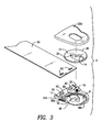
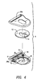
- the preferred means include a fixed attachment means 18, as shown in Figure 3, and a slidable attachment means 18a, as shown in Figure 4.
- the strap 20 is punched with two openings 40 for accepting two raised bosses 42 on the bottom element 22a of the housing.
- the top housing element 22b is then placed over the bottom element 22a which is retaining the strap end and is ultrasonically welded to provide a high strength attachment.
- the fastener 6 includes a slot 18a through which the strap 20 can be fed.
- the strap end is then sewn onto itself or secured onto an adjustment clip, as is known in the art, to provide for a length adjustment of the strap 20 according to the user's size and preference.
- one end of the strap of the present invention would include a fastener 6 with a fixed attachment 18 on one end and an adjustable attachment 18a on the other end.
- the housing 22a and 22b of the preferred embodiment of the present invention is preferably molded of a plastic, and most preferably a high impact resistant plastic such as polycarbonate or acetal.
- the engaging member 12 is preferably made of a high impact resistant plastic such as acetal or nylon.
- the top element 22b of the housing can have an opening to view the engagement of the end pin, as shown, or can be closed for a finished look.
- the fastener 6 of the present invention is intended to fasten a strap to any article which is adapted to include an end pin 2 having reduced diameter portion 4 and a larger terminal portion 28.
- This includes luggage, portfolios, cases, packs, computers or computer cases, and the like as well musical instruments.
- the engaging member 12 can be formed in a linear as well as radial fashion, as long as it serves to define a restrictive element which limits the size of the fastener aperture, as partially defined by the first member 8.
- any locking mechanism for retaining the engaging member can be used, including but not limited to ratchet means and catch/release mechanism or a latch over pressure plate, for example, which restricts movement of the engaging member when positioned in its engagement position.
Landscapes
- Buckles (AREA)
- Purses, Travelling Bags, Baskets, Or Suitcases (AREA)
- Clamps And Clips (AREA)
- Thermistors And Varistors (AREA)
- Finger-Pressure Massage (AREA)
- Package Frames And Binding Bands (AREA)
Abstract
Description
Claims (13)
- A fastener (6) for securing a strap onto an article to be supported, said article having an end pin (2) thereon including a reduced diameter portion (4) and a larger diameter terminal portion, said fastener (6) comprising a first member (8) having a retention portion (10) for receiving the end pin (2), said retention portion (10) defining a first portion of a fastener aperture, and an engaging member (12) having an engagement portion (14) defining a second portion of a fastener aperture, so that movement of the engagement portion (14) of the engaging member (12) relative to the retention portion (10) of the first member (8) defines the size of the fastener aperture.
- The fastener (6) of Claim 1 further comprising locking mechanism (16) for restricting movement of the engagement portion (14) relative to the retention portion, thereby fixing the size of the fastener aperture.
- The fastener (6) of Claim 1 wherein the engaging member (12) comprises a rotatable disk wherein rotation of the disk defines the size of the fastener aperture.
- The fastener (6) of Claim 3 wherein the engagement portion (14) comprises a perimeter of an eccentric aperture (24) on the rotatable disk.
- The fastener (6) of Claim 4 wherein the engagement portion (14) comprises a beveled wall for facilitating engagement of the reduced diameter portion of the end pin.
- The fastener (6) of Claim 3 wherein the outer edge (26) of the rotatable disk is scalloped.
- The fastener (6) of Claim 6 wherein the locking mechanism comprises a ball (30) forced outwardly by a spring (32), said ball (30) engaging concave elements of the scalloped edge (26) of the disk.
- The fastener (6) of Claim 6 wherein the scalloped outer edge (26) has 36 concave elements equally spaced about the outer edge of the disk.
- The fastener (6) of Claim 1 further comprising means for attachment to a strap.
- The fastener (6) of Claim 9 wherein the means for attachment comprises a slot in the fastener through which the strap passes.
- The fastener (6) of Claim 9 wherein the means for attachment comprises one or more raised bosses (42) corresponding to one or more holes in a terminal end of the strap.
- The fastener (6) of Claim 1 further comprising a housing (22a, 22b).
- The fastener (6) of Claim 3 further comprising a housing (22a, 22b) having an opening for exposing at least a portion of the outer edge of the disk.
Applications Claiming Priority (2)
| Application Number | Priority Date | Filing Date | Title |
|---|---|---|---|
| US261842 | 1981-05-08 | ||
| US09/261,842 US6032339A (en) | 1999-03-03 | 1999-03-03 | Locking fastener for a strap |
Publications (3)
| Publication Number | Publication Date |
|---|---|
| EP1033700A2 true EP1033700A2 (en) | 2000-09-06 |
| EP1033700A3 EP1033700A3 (en) | 2002-08-21 |
| EP1033700B1 EP1033700B1 (en) | 2004-10-20 |
Family
ID=22995114
Family Applications (1)
| Application Number | Title | Priority Date | Filing Date |
|---|---|---|---|
| EP00400398A Expired - Lifetime EP1033700B1 (en) | 1999-03-03 | 2000-02-11 | Locking fastener for a strap |
Country Status (7)
| Country | Link |
|---|---|
| US (1) | US6032339A (en) |
| EP (1) | EP1033700B1 (en) |
| JP (1) | JP2000253912A (en) |
| AT (1) | ATE280427T1 (en) |
| AU (1) | AU772152B2 (en) |
| CA (1) | CA2293107C (en) |
| DE (1) | DE60014992D1 (en) |
Cited By (1)
| Publication number | Priority date | Publication date | Assignee | Title |
|---|---|---|---|---|
| EP3690261A4 (en) * | 2017-10-31 | 2020-11-25 | Gotoh Gut Co., Ltd. | Strap pin fitting |
Families Citing this family (23)
| Publication number | Priority date | Publication date | Assignee | Title |
|---|---|---|---|---|
| GB0115974D0 (en) * | 2001-06-29 | 2001-08-22 | Nokia Corp | Removable strap |
| US6665909B2 (en) * | 2001-12-14 | 2003-12-23 | Medtronic Minimed, Inc. | Low-profile mounting clip for personal device |
| FR2845813A1 (en) * | 2002-10-09 | 2004-04-16 | Eisenschmidt | Device for fixing strap on any type of acoustic guitar comprises flat plastic clamp, rounded at top and with double clip at base and is fastened by clip system |
| TW585291U (en) * | 2003-03-25 | 2004-04-21 | Quanta Comp Inc | A strap buckle apparatus for a notebook computer |
| US6845548B1 (en) * | 2003-09-12 | 2005-01-25 | Lifestyle Metal Co., Ltd. | Buckle assembly for mounting goggle on helmet |
| US7562422B2 (en) * | 2004-06-28 | 2009-07-21 | Innovative Automation, Inc. | Locking fastener for a strap |
| US20080020909A1 (en) * | 2006-07-12 | 2008-01-24 | Blair Constance L | Safety Assistance Strap with Bar Attachments |
| US7888572B2 (en) * | 2007-01-05 | 2011-02-15 | Gibson Guitar Corp. | Guitar strap lock |
| US7818851B2 (en) * | 2007-07-25 | 2010-10-26 | Chris Perrotta | Strap lock |
| US8813315B2 (en) | 2007-12-18 | 2014-08-26 | Bryan Schultz | Belt buckle |
| US8171605B2 (en) * | 2007-12-18 | 2012-05-08 | Bryan Schultz | Belt buckle |
| US9131742B2 (en) | 2010-05-27 | 2015-09-15 | Christopher D. Gowen | Chinstrap to helmet connector |
| USD679743S1 (en) * | 2010-09-17 | 2013-04-09 | John Coco | Guitar end pin |
| US8763909B2 (en) * | 2011-01-04 | 2014-07-01 | Hand Held Products, Inc. | Terminal comprising mount for supporting a mechanical component |
| US20130269158A1 (en) * | 2012-04-12 | 2013-10-17 | Microelectronics Technology, Inc. | Positioning pole and a positioning system and a method of positioning a pole to a covering |
| US9220241B2 (en) * | 2012-05-15 | 2015-12-29 | Radio Systems Corporation | Collar strap attachment mechanism |
| USD754536S1 (en) * | 2015-08-12 | 2016-04-26 | Huitzilo Arriaga | Bottle cap with integrated bottle opener |
| US9947303B1 (en) * | 2016-02-12 | 2018-04-17 | Michael H. Dulin | Adapter device for attaching a strap to a musical instrument provided with a strap button |
| US10165840B2 (en) * | 2017-02-04 | 2019-01-01 | I Amika Adams | Locking fastener system |
| EP3773059A4 (en) * | 2018-04-04 | 2021-12-22 | Boss, Todd R. | TRANSPORT STRAPS FOR ELECTRONIC DISPLAY DEVICES |
| USD907977S1 (en) * | 2019-06-17 | 2021-01-19 | Ruth Niles | Tab opener |
| CN214177356U (en) * | 2020-12-31 | 2021-09-10 | 深圳市乐沐营销顾问有限公司 | Rope hanging device |
| US12622493B2 (en) * | 2022-09-09 | 2026-05-12 | Apple Inc. | Head-mountable device band with a latch movable by a tab |
Family Cites Families (18)
| Publication number | Priority date | Publication date | Assignee | Title |
|---|---|---|---|---|
| US705641A (en) * | 1901-04-22 | 1902-07-29 | James Britnell | Corset-fastener. |
| US689991A (en) * | 1901-09-25 | 1901-12-31 | Max Rubin | Suspension-clasp. |
| US703878A (en) * | 1902-04-08 | 1902-07-01 | Frederick Woodward | Means for securing straps to buckles. |
| US828573A (en) * | 1905-12-18 | 1906-08-14 | I B Kleinert Rubber Co | Garment-hanger. |
| US2647294A (en) * | 1949-09-23 | 1953-08-04 | Frank L Davis | Releasable fastener |
| US3743147A (en) * | 1970-12-10 | 1973-07-03 | Motorola Inc | Support for carrying case |
| US4357063A (en) * | 1980-06-06 | 1982-11-02 | Gray William T | Washer anchoring construction |
| US4461594A (en) * | 1981-10-28 | 1984-07-24 | Waber Morris L | Rotatably adjustable and lockable connector |
| US4556133A (en) * | 1983-03-25 | 1985-12-03 | Luk Lamellen Und Kupplungsbau Gmbh | Friction clutch |
| US4676530A (en) * | 1983-04-07 | 1987-06-30 | Warner-Lambert Company | Coupling assembly for use in fluid flow systems |
| US4756654A (en) * | 1984-06-13 | 1988-07-12 | Trw Inc. | Fastening device |
| US4767246A (en) * | 1986-12-05 | 1988-08-30 | Camloh Industries, Inc. | Quick-release tool holding device |
| JPS63168491U (en) * | 1987-04-20 | 1988-11-02 | ||
| US4812094A (en) * | 1987-09-24 | 1989-03-14 | Maclean-Fogg Company | Locking fastener assembly for threaded joint |
| US4993127A (en) * | 1989-09-29 | 1991-02-19 | Standtastic | Locking attachment for guitar straps and the like |
| US5193368A (en) * | 1992-06-10 | 1993-03-16 | Ling Chong Kuan | Combination lock of strap buckle |
| US5746334A (en) * | 1993-11-24 | 1998-05-05 | Brandenberg; Carl Brock | Apparatus for supporting modular and cooperating components |
| US5868293A (en) * | 1997-12-24 | 1999-02-09 | Innovative Automation, Inc. | Quick release guitar strap system |
-
1999
- 1999-03-03 US US09/261,842 patent/US6032339A/en not_active Expired - Lifetime
- 1999-12-23 CA CA002293107A patent/CA2293107C/en not_active Expired - Lifetime
-
2000
- 2000-01-13 AU AU10082/00A patent/AU772152B2/en not_active Ceased
- 2000-01-21 JP JP2000012390A patent/JP2000253912A/en active Pending
- 2000-02-11 EP EP00400398A patent/EP1033700B1/en not_active Expired - Lifetime
- 2000-02-11 DE DE60014992T patent/DE60014992D1/en not_active Expired - Lifetime
- 2000-02-11 AT AT00400398T patent/ATE280427T1/en not_active IP Right Cessation
Cited By (2)
| Publication number | Priority date | Publication date | Assignee | Title |
|---|---|---|---|---|
| EP3690261A4 (en) * | 2017-10-31 | 2020-11-25 | Gotoh Gut Co., Ltd. | Strap pin fitting |
| US10971120B2 (en) | 2017-10-31 | 2021-04-06 | Gotoh Gut Co., Ltd. | Strap pin fitting |
Also Published As
| Publication number | Publication date |
|---|---|
| EP1033700B1 (en) | 2004-10-20 |
| AU772152B2 (en) | 2004-04-08 |
| JP2000253912A (en) | 2000-09-19 |
| EP1033700A3 (en) | 2002-08-21 |
| CA2293107A1 (en) | 2000-09-03 |
| US6032339A (en) | 2000-03-07 |
| DE60014992D1 (en) | 2004-11-25 |
| AU1008200A (en) | 2000-09-07 |
| ATE280427T1 (en) | 2004-11-15 |
| CA2293107C (en) | 2003-07-29 |
Similar Documents
| Publication | Publication Date | Title |
|---|---|---|
| US6032339A (en) | Locking fastener for a strap | |
| US4951817A (en) | Beeper slip on cover | |
| KR100742665B1 (en) | Clip for attaching pouches and similar devices | |
| CA1061991A (en) | Detachable mounting clip arrangement for miniature portable apparatus or the like | |
| US4993127A (en) | Locking attachment for guitar straps and the like | |
| US6470535B1 (en) | Camming belt clip | |
| US20250081940A1 (en) | Collar with integrated device attachment | |
| KR20200020663A (en) | Magnetic hook | |
| US4934520A (en) | Portable valuables receptacle | |
| US6206187B1 (en) | Electronic device retention case | |
| US20060163295A1 (en) | Belt clip | |
| US20040232180A1 (en) | Belt clip and locking fastener for selectively securing an electronic device | |
| US7175213B1 (en) | Handle rotation restraint and method | |
| US20240242056A1 (en) | Mounts for tracking devices | |
| WO2001013356A2 (en) | Strap locking and pick storage device | |
| US20050045021A1 (en) | Strap button and attachment | |
| US5737412A (en) | Portable telephone with a carrying strap | |
| US6108276A (en) | Belt buckle with an attached watch | |
| US5361497A (en) | Folding knife holder and method for one-handed opening of a folding knife | |
| US20020104425A1 (en) | Device for preventing unintentional removal of an end of a guitar strap from an engaged guitar strap peg of a guitar | |
| US7284304B2 (en) | Retaining assembly | |
| US5906303A (en) | Baton holder | |
| USRE29897E (en) | Latching device | |
| US5008974A (en) | Carrying handle assembly | |
| US6253978B1 (en) | Motorcycle saddlebag lock |
Legal Events
| Date | Code | Title | Description |
|---|---|---|---|
| PUAI | Public reference made under article 153(3) epc to a published international application that has entered the european phase |
Free format text: ORIGINAL CODE: 0009012 |
|
| AK | Designated contracting states |
Kind code of ref document: A2 Designated state(s): AT BE CH CY DE DK ES FI FR GB GR IE IT LI LU MC NL PT SE |
|
| AX | Request for extension of the european patent |
Free format text: AL;LT;LV;MK;RO;SI |
|
| 17P | Request for examination filed |
Effective date: 20001123 |
|
| PUAL | Search report despatched |
Free format text: ORIGINAL CODE: 0009013 |
|
| AK | Designated contracting states |
Kind code of ref document: A3 Designated state(s): AT BE CH CY DE DK ES FI FR GB GR IE IT LI LU MC NL PT SE |
|
| AX | Request for extension of the european patent |
Free format text: AL;LT;LV;MK;RO;SI |
|
| AKX | Designation fees paid |
Designated state(s): AT BE CH CY DE DK ES FI FR GB GR IE IT LI LU MC NL PT SE |
|
| 17Q | First examination report despatched |
Effective date: 20030722 |
|
| GRAP | Despatch of communication of intention to grant a patent |
Free format text: ORIGINAL CODE: EPIDOSNIGR1 |
|
| GRAS | Grant fee paid |
Free format text: ORIGINAL CODE: EPIDOSNIGR3 |
|
| GRAA | (expected) grant |
Free format text: ORIGINAL CODE: 0009210 |
|
| AK | Designated contracting states |
Kind code of ref document: B1 Designated state(s): AT BE CH CY DE DK ES FI FR GB GR IE IT LI LU MC NL PT SE |
|
| PG25 | Lapsed in a contracting state [announced via postgrant information from national office to epo] |
Ref country code: IT Free format text: LAPSE BECAUSE OF FAILURE TO SUBMIT A TRANSLATION OF THE DESCRIPTION OR TO PAY THE FEE WITHIN THE PRESCRIBED TIME-LIMIT;WARNING: LAPSES OF ITALIAN PATENTS WITH EFFECTIVE DATE BEFORE 2007 MAY HAVE OCCURRED AT ANY TIME BEFORE 2007. THE CORRECT EFFECTIVE DATE MAY BE DIFFERENT FROM THE ONE RECORDED. Effective date: 20041020 Ref country code: CH Free format text: LAPSE BECAUSE OF FAILURE TO SUBMIT A TRANSLATION OF THE DESCRIPTION OR TO PAY THE FEE WITHIN THE PRESCRIBED TIME-LIMIT Effective date: 20041020 Ref country code: FR Free format text: LAPSE BECAUSE OF FAILURE TO SUBMIT A TRANSLATION OF THE DESCRIPTION OR TO PAY THE FEE WITHIN THE PRESCRIBED TIME-LIMIT Effective date: 20041020 Ref country code: FI Free format text: LAPSE BECAUSE OF FAILURE TO SUBMIT A TRANSLATION OF THE DESCRIPTION OR TO PAY THE FEE WITHIN THE PRESCRIBED TIME-LIMIT Effective date: 20041020 Ref country code: BE Free format text: LAPSE BECAUSE OF FAILURE TO SUBMIT A TRANSLATION OF THE DESCRIPTION OR TO PAY THE FEE WITHIN THE PRESCRIBED TIME-LIMIT Effective date: 20041020 Ref country code: LI Free format text: LAPSE BECAUSE OF FAILURE TO SUBMIT A TRANSLATION OF THE DESCRIPTION OR TO PAY THE FEE WITHIN THE PRESCRIBED TIME-LIMIT Effective date: 20041020 Ref country code: NL Free format text: LAPSE BECAUSE OF FAILURE TO SUBMIT A TRANSLATION OF THE DESCRIPTION OR TO PAY THE FEE WITHIN THE PRESCRIBED TIME-LIMIT Effective date: 20041020 Ref country code: AT Free format text: LAPSE BECAUSE OF FAILURE TO SUBMIT A TRANSLATION OF THE DESCRIPTION OR TO PAY THE FEE WITHIN THE PRESCRIBED TIME-LIMIT Effective date: 20041020 |
|
| REG | Reference to a national code |
Ref country code: GB Ref legal event code: FG4D |
|
| REG | Reference to a national code |
Ref country code: CH Ref legal event code: EP |
|
| REG | Reference to a national code |
Ref country code: IE Ref legal event code: FG4D |
|
| REF | Corresponds to: |
Ref document number: 60014992 Country of ref document: DE Date of ref document: 20041125 Kind code of ref document: P |
|
| PG25 | Lapsed in a contracting state [announced via postgrant information from national office to epo] |
Ref country code: DK Free format text: LAPSE BECAUSE OF FAILURE TO SUBMIT A TRANSLATION OF THE DESCRIPTION OR TO PAY THE FEE WITHIN THE PRESCRIBED TIME-LIMIT Effective date: 20050120 Ref country code: GR Free format text: LAPSE BECAUSE OF FAILURE TO SUBMIT A TRANSLATION OF THE DESCRIPTION OR TO PAY THE FEE WITHIN THE PRESCRIBED TIME-LIMIT Effective date: 20050120 Ref country code: SE Free format text: LAPSE BECAUSE OF FAILURE TO SUBMIT A TRANSLATION OF THE DESCRIPTION OR TO PAY THE FEE WITHIN THE PRESCRIBED TIME-LIMIT Effective date: 20050120 |
|
| PG25 | Lapsed in a contracting state [announced via postgrant information from national office to epo] |
Ref country code: DE Free format text: LAPSE BECAUSE OF FAILURE TO SUBMIT A TRANSLATION OF THE DESCRIPTION OR TO PAY THE FEE WITHIN THE PRESCRIBED TIME-LIMIT Effective date: 20050121 |
|
| PG25 | Lapsed in a contracting state [announced via postgrant information from national office to epo] |
Ref country code: ES Free format text: LAPSE BECAUSE OF FAILURE TO SUBMIT A TRANSLATION OF THE DESCRIPTION OR TO PAY THE FEE WITHIN THE PRESCRIBED TIME-LIMIT Effective date: 20050131 |
|
| PG25 | Lapsed in a contracting state [announced via postgrant information from national office to epo] |
Ref country code: IE Free format text: LAPSE BECAUSE OF NON-PAYMENT OF DUE FEES Effective date: 20050211 Ref country code: GB Free format text: LAPSE BECAUSE OF NON-PAYMENT OF DUE FEES Effective date: 20050211 Ref country code: LU Free format text: LAPSE BECAUSE OF NON-PAYMENT OF DUE FEES Effective date: 20050211 Ref country code: CY Free format text: LAPSE BECAUSE OF FAILURE TO SUBMIT A TRANSLATION OF THE DESCRIPTION OR TO PAY THE FEE WITHIN THE PRESCRIBED TIME-LIMIT Effective date: 20050211 |
|
| PG25 | Lapsed in a contracting state [announced via postgrant information from national office to epo] |
Ref country code: MC Free format text: LAPSE BECAUSE OF NON-PAYMENT OF DUE FEES Effective date: 20050228 |
|
| REG | Reference to a national code |
Ref country code: CH Ref legal event code: PL |
|
| NLV1 | Nl: lapsed or annulled due to failure to fulfill the requirements of art. 29p and 29m of the patents act | ||
| PLBE | No opposition filed within time limit |
Free format text: ORIGINAL CODE: 0009261 |
|
| STAA | Information on the status of an ep patent application or granted ep patent |
Free format text: STATUS: NO OPPOSITION FILED WITHIN TIME LIMIT |
|
| GBPC | Gb: european patent ceased through non-payment of renewal fee |
Effective date: 20050211 |
|
| 26N | No opposition filed |
Effective date: 20050721 |
|
| REG | Reference to a national code |
Ref country code: IE Ref legal event code: MM4A |
|
| EN | Fr: translation not filed | ||
| PG25 | Lapsed in a contracting state [announced via postgrant information from national office to epo] |
Ref country code: PT Free format text: LAPSE BECAUSE OF NON-PAYMENT OF DUE FEES Effective date: 20050320 |