EP1033681A2 - Method and apparatus for image data compression - Google Patents
Method and apparatus for image data compression Download PDFInfo
- Publication number
- EP1033681A2 EP1033681A2 EP00104710A EP00104710A EP1033681A2 EP 1033681 A2 EP1033681 A2 EP 1033681A2 EP 00104710 A EP00104710 A EP 00104710A EP 00104710 A EP00104710 A EP 00104710A EP 1033681 A2 EP1033681 A2 EP 1033681A2
- Authority
- EP
- European Patent Office
- Prior art keywords
- plane
- image
- planes
- pixels
- selector
- Prior art date
- Legal status (The legal status is an assumption and is not a legal conclusion. Google has not performed a legal analysis and makes no representation as to the accuracy of the status listed.)
- Granted
Links
Images




Classifications
-
- G—PHYSICS
- G06—COMPUTING OR CALCULATING; COUNTING
- G06T—IMAGE DATA PROCESSING OR GENERATION, IN GENERAL
- G06T9/00—Image coding
- G06T9/001—Model-based coding, e.g. wire frame
Definitions
- This invention relates to the representation of digital images, particularly the representation of those digital images in compressed format.
- the invention is also related to the representation of digital images in multiple planes of like, similar, or related data traits or values.
- the invention is more particularly related to the optimization of a plane of a digital image for a selected compression methodology and for storing correction data for the optimized plane in an alternate plane of the image.
- the invention is also related to the reconstruction of a representation of a digital image by selecting data from either an optimized plane of a representation of the digital image and an additive plane comprising additive data from each of the optimized plane and a correction plane.
- the efficient transmission, exchange, and storage of image data is a key issue in distributed systems.
- the main difficulty is to find effective ways of significantly reducing the large amount of information that needs to be transferred and/or processed, while still being able to reconstruct the image with good fidelity.
- the conventional approach to deal with this problem is to reduce the amount of data by applying compression.
- compression technique such as LZW, JPEG, JBIG, and Wavelets
- binary compression schemes such as LZW are very effective in dealing with text and line-art information
- JPEG has been successfully developed to encode natural photographs.
- these algorithms have been designed to perform well on a particular class (be it textual or pictorial) of images - and no single algorithm can possibly handle all types of image classes reasonably well.
- the Document Image Representation is one way of describing digital documents based on this concept.
- the current DIR model is represented using three different (logical) planes, as shown in Figure 1: An upper plane Up, also referred to as the foreground plane, typically containing data that puts high requirements on detail such as text and line-art; A purely binary selector plane Sp, or mask plane, that provides switching information between the upper and lower planes; And a lower plane Lp, also referred to as the background plane, that emphasizes color gradation, such as images and sweeps.
- the contents of the planes in Figure 1 is shown just for the purpose of illustration.
- Other variations are also possible.
- the embedded imaging model within DIR will be referred to as the Selective Model, since content of the upper plane is used to overwrite the content of the lower plane, on a pixel by pixel basis, whenever the selector plane is true.
- the upper plane data is "poured" through the binary selector plane, to replace the lower plane data below. Note that at the end, each reconstructed pixel carries information from either the upper or lower planes. That is, the information present in the other plane (the one not selected by the mask) is considered irrelevant and is ignored.
- the upper and lower planes are usually compressed using very different compression schemes.
- the DIR specification recommends, as an example, use of the following algorithms (DIR spec, p. 8): Fiala-Green (LZW related) for text and line-art (Upper plane), CCITT group 3/4 for the binary mask (Selector plane), and JPEG for color images and sweeps (Lower plane).
- LZW Fiala-Green
- CCITT group 3/4 for the binary mask
- JPEG color images and sweeps
- the present inventors have realized that a decision to enforce one of the planes at all times limits the flexibility of a representation model.
- an object of the present invention to provide an image compressor and a method of image compression/representation that varies an amount of detail contained in any of plural image planes representing an image.
- a method of decompressing an image including the steps of decompressing an upper plane of an image, decompressing a lower plane of an image, adding the decompressed upper plane and the decompressed lower plane to produce an additive image, and selecting pixels of a final decompressed image from one of the decompressed lower plane and the additive image.
- the step of selecting pixels may include the step of varying an amount of the additive image produced by the upper plane based on a predetermined factor.
- a compression apparatus including means for compressing an upper plane of an image and a lower plane of an image, wherein an amount of detail of the image contained in pixels of the compressed upper plane increases with respect to a predetermined factor of corresponding pixels in the image.
- the predetermined factor may be one of a degree of color in the corresponding pixels matching a background color of the image and an amount of fine edge positions in the corresponding pixels.
- the Document Image Representation (DIR) specification provides a way of describing digital documents by separating textual (line-art) information from continuous-tone pictures and applying different compression on each component, to take advantage of its specific attributes.
- the imbedded imaging model a Selective Model
- the information must always be classified and strictly carried in one of two channels, but never in both.
- the present invention improves and further enhances the existing DIR representation to eliminate the above discussed limitations. Specifically it offers to replace the Selective Imaging Model with an Additive Imaging Model, thereby allowing the flexibility to combine information from both channels to make the best use of available compression resources. In addition, it offers to optionally extend the selector plane beyond binary. These modifications define a new and more flexible method of representing digital documents, that may lead to substantial improvements both in quality and compression results when compared with the existing method. The improvements are demonstrated in a case study example discussed hereinbelow.
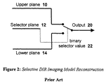
- the output image 20 is reconstructed from the DIR representation (the three planes described above, comprising of an upper, lower, and binary selector plane) using a simple multiplex operation.
- the binary selector value 22, derived from the selector plane is used to choose data from either the upper plane 10 or lower plane 12, on a pixel by pixel basis. Note that any information that might be present in the other plane (the one not selected by the mask) is ignored and treated as irrelevant.
- the problem with this model is that a decision must be made for each and every pixel: to select one of the upper or lower planes.
- the DIR spec does not specify a recommendation as to how to make that decision, so in theory full freedom exists.
- the DIR specification does make a recommendation to use certain standard block based compression techniques for some of the planes (e.g., the use of JPEG for compressing the lower plane). This indirectly implies that the pixels in a block are tied together via the compression, regardless of how they are classified.
- a block of pixels situated on the text boundary will occasionally contain a portion of the text as well as a portion the image.
- the text portion could be "lifted" off the image to be encoded in the upper plane, and the remainder is left to be JPEG'ed in the lower plane.
- the lifted text pieces may end up affecting the quality or compression ratio of the non-textual areas nearby.
- the current DIR specification recommends the use of a variant of LZW for compressing the upper plane. This technique favors binary situations with few colors in order to achieve high compression ratios. If several pixels within a block are classified as line-art, and all have different colors (possibly due to noise variations), then the resulting compression performance may drop substantially (as will be demonstrated by the example below).
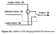
- Fig. 3a As an alternative, consider the new Additive Imaging Model proposed in this invention as illustrated in Fig. 3a.
- This model has the advantage in reconstruction, whereby information from an upper plane 32 is first (prior to making the selection) added to the content of a lower plane 36.
- adder 38 combines data from the two channels (Upper plane 32 and lower plane 36), thereby providing a mechanism to correct for representation errors resulting from the classification adjustments discussed above.
- the adder may be implemented in alternative ways.
- the adder may be utilized to combine pixels from the upper and lower planes at the time of selection.
- the adder may be utilized to combine the upper and lower planes to produce an additive image, and then the selector chooses pixels from either one of the upper plane (in this embodiment) and the additive image.
- selector chooses pixels from either one of the upper plane (in this embodiment) and the additive image.
- other configurations to procure the same end result are also possible (selections based on blocks or clusters, as one example).
- the Additive Imaging Model can significantly improve the results. For example, given the type of upper plane compression used, the foreground color may be forced to be composed of a limited number of colors (a decision likely to substantially improve the compression), or even to "not-so-close colors", yet compensate for this via the background channel (lower plane in this example). We do so by calculating the individual pixel errors resulting from such a decision, and then subtracting this error from the background value. Furthermore, we can also individually (on a pixel by pixel basis) control how much of the modeling error we wish to carry in each of the channels. This enables compression and quality to be optimized together. It is a huge benefit for the cost of adding a single adder (which may be implemented in either software or hardware).
- the Additive Model can also be naturally extended to provide greater resolution for edge detail. Current practice seems to indicate that having a selector plane at higher resolutions is desirable whenever the input resolution is below 600 dpi. For this range, typical Resolution Enhancement techniques (Ret) have been successfully employed to anti-alias (smooth) text and line-ad to improve its appearance.
- Ret Resolution Enhancement techniques
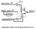
- a non-binary selector plane may be utilized. With more than one bit, the selector plane naturally extends to become an alpha channel for mixing (or blending) information between the upper and lower planes. Of course, one would want to limit the number of bits allocated to the selector plane for better compression, but in some situations additional selector plane bits may be advantageous.
- a detector 38 interprets a value and read from a multi-bit selector plane which is utilized to alter (see amp/mixers 39a and 39b) values read from each of an upper plane 33 and lower plane 37 prior to producing an additive plane (via adder 40).
- the extra bits in the selector plane are used as weights to vary the mixing proportions of the two channels.
- One useful application of such non-binary selector could be super-resolution, or fine edge positioning. The closer the edge is, the more weight is given to the foreground as opposed to the background. This technique can eliminate the need for having REt (as a post-processing step) to enhance text and line-art appearance.
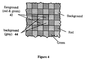
- the input image is composed of a page that is fully covered with the regular pattern shown (the motivation for choosing this example will become apparent from the description below).
- the pattern is based on a basic four-quadrant cell whose building element is encapsulated within the center dark frame 40 in Figure 4. This cell is then regularly tiled over the page to create the complete pattern.
- the main idea here is to have a relatively "clean" two-color foreground texture on top of some noisy background image, similar to what one would get when scanning colored text or line-art on top of an image.
- This example is extreme in the sense that every image cell contains a mixture of dual-color foreground and background, a situation not likely to occur very often. In practice, the number of such mixed cells will vary widely, depending on page complexity and segmentation details. Nonetheless, useful insight can be learned from this example.
- the pattern of interest was generated using Adobe Photoshop for the purpose of evaluating the compression results.
- the method of generating the pattern was by filling an 8 x 8 pixel area with the two solid red/green foreground colors, leaving the two background quadrants as a transparent layer. This area was then tiled to fill an image of the same size as the input image, and independent random Gaussian noise was added everywhere (for all pixels).
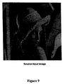
- the pattern image was applied (using a mask operation) to a given background image (a scanned image of "Lenna", cf. Figure 9) of equal size such that the background data was propagated through the "holes" in the mask.
- Figures 5a - 5f demonstrate some of the possible ways for representing this tile image according to a DIR representation compatible with the current specification (based on the existing Selective Model).
- case 5b for example;
- the red quadrant information is classified to be in the upper plane, while the three other quadrants are left in the lower plane.
- the yellow squares indicate areas of irrelevant information in the content of both the upper and lower planes. Since it does not matter what is in there, the best utilization of this space is to fill it in with values that make the corresponding compression as tight as possible (e.g., for case 5b above, one might as well fill the whole upper plane with red everywhere, since this will undoubtedly lead to the highest compression ratio).
- Fig. 5e may lead to better overall compression than 5a and 5b with respect to both the upper and lower planes combined. None-the-less, it has a more complex selector structure (checkerboard pattern) that might not be as effective to compress (with Lossless fax Group 4 CCITT). If both the red and green are sufficiently dark to be true foreground, the preferred representation might well be the one in case 5e, for the selector plane in this case truly represents the binary mask.
- case 5d is like 5e, except the role of the foreground and background planes are reversed. Again, for a given choice of compression pair (i.e., LZW and JPEG) tied to planes at hand, one of these cases may perform significantly worse. Similar "role-reversal" situations also exist for cases 5b and 5c, but are not shown.
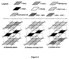
- Figure 6a the input image is separated into the three planes (conceptually similar to Figure 5e).
- Figure 5e One difference being that the lower plane information is always used (due to the additivity) and therefore must be set to some meaningful value (typically the average background color).
- step 2 Figure 6b, the red and green are replaced by a single color (the average foreground) that best represents both colors (denoted as dark gray color in Figure 6b and 6c).
- the difference between this average and each of the two colors is then added to the lower plane in step 3 as seen in Figure 6c.
- the color coding scheme illustrated is that the inverse of red is cyan, and the inverse of green is magenta. Note, however, that if both "red" and "green" colors have been identified as foreground, then they are generally of significant contrast and would typically be closer to each other (in luminance) than to the background.
- the three planes are then compressed as before.
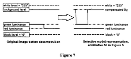
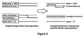
- FIG. 7 A one-dimensional, luminance only, illustration of the above procedure is illustrated in Figure 7.
- a luminance projection of Figure 6a There is a (slowly varying) background level on the lower plane, and alternating red/green checkers on the upper plane. The content of selector plane is not shown.
- both the red and green luminance are replaced with the average luminance level, and the background level is compensated by the difference in luminance. Note that before compression, both of these representations are error-free, that is - lossless.
- the current approach can only obtain similar compression results (i.e., constant upper plane) by picking a single foreground color (preferably the darkest) into the upper plane, and (a-symmetrically) alternating between the other foreground color and background in the lower plane (see Figure 7).
- Such schemes unnecessarily lead to larger degradation in image quality (noticeable ringing artifacts) for the same level of compression, or vice versa.
- the error will generally be signed. If the error becomes large in magnitude, and the background is already very light, there is risk that the result could overflow (the 8 bit range) when the error is compensated for. In our example, since the error was small by construction (only 5 units in luminance (L*), and the image was never too light to go out of range.
- One possible solution to this problem is to limit the error magnitude (by reducing the foreground level) such that it will be made to fit. This is another example of the greater flexibility of the proposed approach, where this time some compression is traded for keeping the representation word size fixed.
- Figures 10a through 10c show the current DIR representation, following the Selective Imaging Model.
- Figure 10a shows the upper plane, composed of alternating (noisy) stripes of red and green.
- data that exist where the selector plane is false was filled with the average color of the four surrounding 4 x 4 quadrants directly above, below, and to the left/right of the quadrant to which it belongs.
- Figure 10b depicts the binary mask, where black corresponds to "0", or false.
- Figure 10c describes the lower plane.
- the original (clean) version of "Lenna” was subsampled by a factor of 8 in each direction, then it was expanded back to the full size (using bi-cubic averaging each time).
- the low-resolution data so created was then used to replace the red/green checker pattern in the lower plane prior to applying the JPEG compression. Note that this method of replacing data for improving compression is the cause for the noticeable edge artifacts; Whenever the image content is relatively flat, the above averaging operation is indistinguishable from the background. On edges, however, this averaging tend to blend colors together, and therefore becomes more noticeably different.
- Figures 11a - 11c show how the same image would be represented using the proposed Additive Imaging Model.
- Figure 9 shows the source image for reference.
- the selector plane ( Figure 11b) is also identical to the one in Figure 10b.
- the number of foreground colors has been chosen to be just one color, knowing that this will compress very well in LZW.
- select the one color all the foreground red and green pixels have been averaged together to form the single dark color shown in Figure 11a. This single color was then used to fill in the complete foreground (Upper) plane.
- the added flexibility of the Additive Model allows one to choose how to fine-tune the data between the upper and lower planes as to make the overall compression as tight as possible.
- the resulting lower plane is given in Figure 11c.
- the outcome can be reasoned as following: The foreground red color happens to be darker than the green (L* value of 40 versus 50). Where the red foreground pixels used to be, the error-adjusted pixels appear to be slightly darker and redder. This is due to the fact that the average foreground color is lighter (L* value of approximately 45), and close to neutral. Therefore the error is making the background redder, and slightly darker. Similarly, where the green pixels used to be, the error-corrected background is made lighter and greener. Since the image has a relatively large red component almost everywhere, this is seen as taking away some red (making it appear to be more greenish-yellow, particularly as seen on the skin tones).
- Table 1 summarizes resulting file sizes, quality, and compression ratios obtained.
- the proposed Additive technique is clearly far superior (by an order of magnitude) as compared to the existing Selective approach, both in overall compression, as well as in the quality and accuracy of reconstruction.
- Image/Plane Existing Selective Model Proposed Additive Model file size (bytes) Compression ratio reconstruction quality file size (bytes) com-pression ratio reconstruction quality
- the present invention may be conveniently implemented using a conventional general purpose or a specialized digital computer or microprocessor programmed according to the teachings of the present disclosure, as will be apparent to those skilled in the computer art.
- the present invention includes a computer program product which is a storage medium (media) having instructions stored thereon/in which can be used to program a computer to perform any of the processes of the present invention.
- the storage medium can include, but is not limited to, any type of disk including floppy disks, optical discs, DVD, CD-ROMs, microdrive, and magneto-optical disks, ROMs, RAMs, EPROMs, EEPROMs, DRAMs, VRAMs, flash memory devices, magnetic or optical cards, nanosystems (including molecular memory ICs), or any type of media or device suitable for storing instructions and/or data.
- the present invention includes software for controlling both the hardware of the general purpose/specialized computer or microprocessor, and for enabling the computer or microprocessor to interact with a human user or other mechanism utilizing the results of the present invention.
- software may include, but is not limited to, device drivers, operating systems, and user applications.
- computer readable media further includes software for performing at least one of additive model representation and reconstruction.
- ⁇ Included in the programming (software) of the general/specialized computer or microprocessor are software modules for implementing the teachings of the present invention, including, but not limited to, separating planes of a source image, averaging at least one of foreground and background colors, replacing colors, and compensating for error introduced by color replacement in one plane by feeding error into a second plane, storage, communication of results, and reconstructing an image according to the processes of the present invention.
- the method further comprises the step of maintaining a selector plane that identifies whether any specific pixel of said upper plane or a combination of the specific pixel and an adjusted lower plane pixel represent corresponding pixels in the image.
- the method further comprises the step of compressing the selector plane.
- the said step of replacing comprises selecting a color of said upper plane and replacing any non-selected colors in said upper plane with the selected color.
- said selected color is an average of colors contained in said upper plane.
- the method further comprises the step of adjusting a level of color in said upper plane to a level such that said step of adjusting said lower plane does not overflow a number of bits utilized to represent said lower level.
- the method further comprises the steps of determining an average color of a number of colors in an upper plane of said plural planes, replacing each color in said upper plane with said average color and adjusting a lower plane at locations corresponding to a respective replaced color of said upper plane with an error value, so that an addition of said lower and upper planes at a location corresponding to a replaced color equals the replaced color.
- said step of dividing includes the step of adjusting an amount of detail of the image contained in pixels of each plane based on a predetermined factor of corresponding pixels in said image.
- said step of adjusting an amount of detail comprises adjusting an amount of detail of the image contained in pixels of an upper plane based on a degree of color in said corresponding pixels matching a background color of said image.
- said step of adjusting an amount of detail comprises adjusting an amount of detail of the image contained in pixels of an upper plane based on an amount of fine edge positions in said corresponding pixels and maintaining multibit selector plane.
- the method further comprises the step of maintaining a multibit selector plane identifying an amount of detail of the image maintained in each of said plural planes.
- each corresponding compression method is selected to match the image characteristics maintained in each plane.
- the corresponding compression method for said selector plane is a lossless compression method.
- said selected color comprises one of a selected color from colors present in said upper plane and an average color of said colors present in said upper plane.
- said selected color comprises a color calculated to provide a best compression result of the upper plane.
- the apparatus further comprises an adjustment device configured to adjust an overall color level of said upper plane so that said error device does not overflow a number of bits allocated for storage of said lower plane pixels and said error.
- the apparatus further comprises a selector device configured to produce a selection mask that identifies how each pixel of the compressed image is stored between the upper and lower planes.
Landscapes
- Engineering & Computer Science (AREA)
- Multimedia (AREA)
- Physics & Mathematics (AREA)
- General Physics & Mathematics (AREA)
- Theoretical Computer Science (AREA)
- Compression Of Band Width Or Redundancy In Fax (AREA)
- Compression Or Coding Systems Of Tv Signals (AREA)
- Image Processing (AREA)
- Controls And Circuits For Display Device (AREA)
Abstract
Description
| Image/Plane | Existing Selective Model | Proposed Additive Model | ||||
| file size (bytes) | Compression ratio | reconstruction quality | file size (bytes) | com-pression ratio | reconstruction quality | |
| Source Image | 786,432 | 786,432 | ||||
| Upper Plane | 412,601 | 1.91 | 3+header | 262,144 | ||
| Selector plane | 13,875 | 56.68 | 13,875 | 56.68 | ||
| Lower plane | 49,945 | 15.75 | 53,654 | 14.66 | ||
| Total Representation Size | 476,421 | 1.651 | good | 67,564 | 11.64 | excellent |
Claims (23)
- A method of compressing an image, comprising the steps of:dividing the image into plural planes; andcompressing each plane with a corresponding selected compression method.
- The method according to Claim 1, further comprising the steps of:replacing colors in at least one of said plural planes with at least one replacement color; andadjusting at least one other of said plural planes, at locations corresponding to the replaced colors, with error values representing a difference between the replaced colors and the corresponding replacement color.
- The method according to Claim 2, further comprising the step of:maintaining a selector plane that identifies one of a plane of said plural planes and a combination of said plural planes that maintain pixels representing the image.
- The method according to Claim 1, wherein:said step of dividing comprises dividing the image into at least an upper plane and a lower plane; andsaid method further comprises the steps of,replacing colors in said upper plane with a replacement color; andadjusting said lower plane at locations corresponding to a respective replaced color with an error value representing a difference between the respective replaced color and the replacement color.
- A method for reconstruction of an image, comprising the steps of:selecting pixels of the image to be reconstructed from plural planes of data representing the image.
- The method according to Claim 5, wherein:said step of selecting, comprises,selecting pixels of the image from one of a single plane and an arithmetic operation of pixels from more than one of said plural planes.
- The method according to Claim 5, wherein:said step of selecting comprises the step of,selecting pixels based on a selector plane that identifies, for each part of the original image, whether the original image information is maintained in an upper plane or a combination of the upper and at least one lower plane of said plural planes.
- The method according to Claim 5, further comprising the step of:decompressing said plural planes, including at least an upper plane and a lower plane, from a compressed state.
- The method according to Claim 8, wherein:said step of selecting comprises,combining said upper and lower decompressed planes to produce an additive image, andselecting pixels of the reconstructed image from corresponding pixel locations of one of said decompressed upper plane and said additive image.
- The method according to Claim 8, wherein:said step of decompressing includes the step of,decompressing a selector plane maintaining information identifying which pixels of each other decompressed plane are representative of pixels of the reconstructed image; andsaid step of selecting comprises,selecting pixels for the reconstructed image based on the selector plane information.
- An apparatus for representing a source image, comprising:a divider configured to divide the source image into at least an upper and a lower plane;a color replacement device configured to replace colors in said upper plane with a selected color; andan error device configured feed pixel errors in said upper plane resulting from said color replacement into corresponding pixel locations in said lower plane.
- The apparatus according to Claim 11, further comprising:a selector device configured to build a selector plane identifying pixels of said source image contained in said upper plane and a combination of said upper plane and said lower plane.
- The apparatus according to Claim 12, further comprising:a compressor configured to compress each of said upper, lower, and selector planes with a corresponding compression method.
- An apparatus for reconstructing an image, comprising:a decompression device configured to decompress planes representing the image; anda selection device configured to select image data from at least one of the planes and an arithmetic operation between corresponding image sections of at least two of the decompressed planes to reconstruct the image.
- The apparatus according to Claim 14, wherein said selection device is further configured to weight an amount of said result derived from said upper plane based on a predetermined factor.
- The apparatus according to Claim 15, wherein said predetermined factor is a value of a selector plane that identifies how much of said result is derived from each of said upper and lower planes.
- The apparatus according to Claim 16, wherein said value of said selector plane is based on at least one of super-resolution and fine edge detail in corresponding locations of said image.
- An apparatus for representing an image comprising:means for dividing the image into plural planes;means for replacing colors in a plane of the image;means for feeding an error representing a difference between the replaced color and the replacement color in another plane of the image; andmeans for producing a selector mask that,identifies pixels in each plane that correspond to pixels of the image being represented, andidentifies combinations of pixels of said plural planes that correspond to pixels of the image being represented.
- The apparatus according to Claim 18, further comprising:means for compressing each of said plural planes and said selector mask with a compression method matching characteristics of each respective plane and mask.
- An apparatus for image reconstruction, comprising:means for reconstructing an image based on pixels selected from one of at least one of plural planes representing the image and an arithmetic operation between corresponding pixels of at least two of said plural planes.
- The apparatus according to Claim 20, further comprising:means for decompressing said plural planes and at least one selection mask of the image to be reconstructed.
- The apparatus according to Claim 20, wherein said means for reconstructing includes means for selecting pixels based on said at least one selector mask.
- A computer readable media, storing instructions, that when loaded into a computer, cause the computer to perform the steps according to the method of one of claims 1 to 10.
Applications Claiming Priority (2)
| Application Number | Priority Date | Filing Date | Title |
|---|---|---|---|
| US262362 | 1999-03-04 | ||
| US09/262,362 US6920250B1 (en) | 1999-03-04 | 1999-03-04 | Additive model for efficient representation of digital documents |
Publications (3)
| Publication Number | Publication Date |
|---|---|
| EP1033681A2 true EP1033681A2 (en) | 2000-09-06 |
| EP1033681A3 EP1033681A3 (en) | 2003-07-23 |
| EP1033681B1 EP1033681B1 (en) | 2007-03-07 |
Family
ID=22997172
Family Applications (1)
| Application Number | Title | Priority Date | Filing Date |
|---|---|---|---|
| EP00104710A Expired - Lifetime EP1033681B1 (en) | 1999-03-04 | 2000-03-03 | Method and apparatus for image data compression |
Country Status (4)
| Country | Link |
|---|---|
| US (2) | US6920250B1 (en) |
| EP (1) | EP1033681B1 (en) |
| JP (1) | JP4413363B2 (en) |
| DE (1) | DE60033716T2 (en) |
Cited By (3)
| Publication number | Priority date | Publication date | Assignee | Title |
|---|---|---|---|---|
| WO2008135440A3 (en) * | 2007-05-04 | 2009-04-16 | Iris Sa | Compression of digital images of scanned documents |
| CN108961299A (en) * | 2017-05-18 | 2018-12-07 | 北京金山云网络技术有限公司 | A kind of foreground image preparation method and device |
| CN111104935A (en) * | 2019-11-08 | 2020-05-05 | 浙江口碑网络技术有限公司 | Image acquisition method and image display method, device and equipment |
Families Citing this family (11)
| Publication number | Priority date | Publication date | Assignee | Title |
|---|---|---|---|---|
| JP3197098B2 (en) | 1993-03-16 | 2001-08-13 | 東京瓦斯株式会社 | Hydrogen production equipment |
| US8416847B2 (en) * | 1998-12-21 | 2013-04-09 | Zin Stai Pte. In, Llc | Separate plane compression using plurality of compression methods including ZLN and ZLD methods |
| JP2003116004A (en) * | 2001-10-04 | 2003-04-18 | Seiko Epson Corp | Image file with transparency |
| US7606417B2 (en) * | 2004-08-16 | 2009-10-20 | Fotonation Vision Limited | Foreground/background segmentation in digital images with differential exposure calculations |
| US20050157949A1 (en) * | 2003-09-30 | 2005-07-21 | Seiji Aiso | Generation of still image |
| US8106956B2 (en) * | 2005-06-27 | 2012-01-31 | Nokia Corporation | Digital camera devices and methods for implementing digital zoom in digital camera devices and corresponding program products |
| IES20060559A2 (en) | 2006-02-14 | 2006-11-01 | Fotonation Vision Ltd | Automatic detection and correction of non-red flash eye defects |
| US7831108B2 (en) | 2006-12-13 | 2010-11-09 | Adobe Systems Incorporated | Universal front end for masks, selections, and paths |
| US7701470B2 (en) * | 2006-12-13 | 2010-04-20 | Adobe Systems, Incorporated | Stable mask combination in digital image editing |
| US8406566B1 (en) * | 2010-05-27 | 2013-03-26 | Adobe Systems Incorporated | Methods and apparatus for soft edge masking |
| US8824031B2 (en) | 2012-06-28 | 2014-09-02 | Xerox Corporation | Method and apparatus for object assisted image editing and transmission of scanned documents |
Family Cites Families (10)
| Publication number | Priority date | Publication date | Assignee | Title |
|---|---|---|---|---|
| US4558302A (en) | 1983-06-20 | 1985-12-10 | Sperry Corporation | High speed data compression and decompression apparatus and method |
| WO1994006111A1 (en) * | 1992-09-08 | 1994-03-17 | Analog Devices, Incorporated | Crt display apparatus with improved techniques for blending video signals with computer-generated graphic signals |
| JP2705744B2 (en) | 1992-11-13 | 1998-01-28 | 富士ゼロックス株式会社 | Image encoding device and decoding device |
| JP2800633B2 (en) | 1993-04-30 | 1998-09-21 | 富士ゼロックス株式会社 | Image coding device |
| JPH0795417A (en) | 1993-09-27 | 1995-04-07 | Toshiba Corp | Image data encoding and decoding device |
| US5778095A (en) * | 1995-12-20 | 1998-07-07 | Xerox Corporation | Classification of scanned symbols into equivalence classes |
| US5778092A (en) * | 1996-12-20 | 1998-07-07 | Xerox Corporation | Method and apparatus for compressing color or gray scale documents |
| US5900953A (en) * | 1997-06-17 | 1999-05-04 | At&T Corp | Method and apparatus for extracting a foreground image and a background image from a color document image |
| JP2000175052A (en) * | 1998-12-07 | 2000-06-23 | Xerox Corp | Processing method and system for pixel map expression |
| US7200263B2 (en) * | 2002-07-01 | 2007-04-03 | Xerox Corporation | Background suppression and color adjustment method |
-
1999
- 1999-03-04 US US09/262,362 patent/US6920250B1/en not_active Expired - Fee Related
-
2000
- 2000-03-03 EP EP00104710A patent/EP1033681B1/en not_active Expired - Lifetime
- 2000-03-03 DE DE60033716T patent/DE60033716T2/en not_active Expired - Lifetime
- 2000-03-06 JP JP2000061251A patent/JP4413363B2/en not_active Expired - Fee Related
-
2004
- 2004-09-22 US US10/946,846 patent/US7340090B2/en not_active Expired - Fee Related
Cited By (4)
| Publication number | Priority date | Publication date | Assignee | Title |
|---|---|---|---|---|
| WO2008135440A3 (en) * | 2007-05-04 | 2009-04-16 | Iris Sa | Compression of digital images of scanned documents |
| CN108961299A (en) * | 2017-05-18 | 2018-12-07 | 北京金山云网络技术有限公司 | A kind of foreground image preparation method and device |
| CN108961299B (en) * | 2017-05-18 | 2021-03-02 | 北京金山云网络技术有限公司 | Method and device for obtaining foreground image |
| CN111104935A (en) * | 2019-11-08 | 2020-05-05 | 浙江口碑网络技术有限公司 | Image acquisition method and image display method, device and equipment |
Also Published As
| Publication number | Publication date |
|---|---|
| US7340090B2 (en) | 2008-03-04 |
| EP1033681B1 (en) | 2007-03-07 |
| JP2000299789A (en) | 2000-10-24 |
| JP4413363B2 (en) | 2010-02-10 |
| EP1033681A3 (en) | 2003-07-23 |
| DE60033716D1 (en) | 2007-04-19 |
| DE60033716T2 (en) | 2007-06-28 |
| US6920250B1 (en) | 2005-07-19 |
| US20050041855A1 (en) | 2005-02-24 |
Similar Documents
| Publication | Publication Date | Title |
|---|---|---|
| US6920250B1 (en) | Additive model for efficient representation of digital documents | |
| US7366357B2 (en) | Systems and methods for adjusting image data to form highly compressible image planes | |
| US6701012B1 (en) | Out-of-layer pixel generation for a decomposed-image layer | |
| CN101938650B (en) | Image compressing apparatus, image compressing method, image decompressing apparatus, image decompressing method, image forming apparatus | |
| AU2006246497B2 (en) | Method and apparatus for hybrid image compression | |
| DE69809157T2 (en) | Image encoding apparatus and method, image decoding apparatus and image forming apparatus | |
| US8849021B2 (en) | Image processing apparatus, method, and storage medium for high speed compression processing | |
| JP3843581B2 (en) | Image encoding device, image decoding device, image processing device, image encoding method, image decoding method, and image processing method | |
| US7991235B2 (en) | Light compression for color images using error diffusion | |
| JP2007028408A (en) | Image processing apparatus | |
| US7065254B2 (en) | Multilayered image file | |
| JP2011193394A (en) | Image processing apparatus, image processing method, and program | |
| US7190837B2 (en) | Compression of mixed raster content (MRC) image data | |
| US7620256B2 (en) | Method and apparatus for processing images in a layered structure | |
| Buckley et al. | New developments in color facsimile and internet fax | |
| JP2003046789A (en) | Image encoding device and image decoding device | |
| JP3376870B2 (en) | Image processing device | |
| EP1006715A2 (en) | Processing digital image data | |
| JP4047207B2 (en) | Image coding apparatus, image coding method, and program | |
| Ueda et al. | Reversible Data Hiding Associated with Digital Halftoning That Allows Printing with Special Color Ink by Using Single Color Layer |
Legal Events
| Date | Code | Title | Description |
|---|---|---|---|
| PUAI | Public reference made under article 153(3) epc to a published international application that has entered the european phase |
Free format text: ORIGINAL CODE: 0009012 |
|
| AK | Designated contracting states |
Kind code of ref document: A2 Designated state(s): AT BE CH CY DE DK ES FI FR GB GR IE IT LI LU MC NL PT SE |
|
| AX | Request for extension of the european patent |
Free format text: AL;LT;LV;MK;RO;SI |
|
| PUAL | Search report despatched |
Free format text: ORIGINAL CODE: 0009013 |
|
| AK | Designated contracting states |
Designated state(s): AT BE CH CY DE DK ES FI FR GB GR IE IT LI LU MC NL PT SE |
|
| AX | Request for extension of the european patent |
Extension state: AL LT LV MK RO SI |
|
| 17P | Request for examination filed |
Effective date: 20040123 |
|
| 17Q | First examination report despatched |
Effective date: 20040302 |
|
| AKX | Designation fees paid |
Designated state(s): DE FR GB |
|
| GRAP | Despatch of communication of intention to grant a patent |
Free format text: ORIGINAL CODE: EPIDOSNIGR1 |
|
| GRAS | Grant fee paid |
Free format text: ORIGINAL CODE: EPIDOSNIGR3 |
|
| GRAA | (expected) grant |
Free format text: ORIGINAL CODE: 0009210 |
|
| AK | Designated contracting states |
Kind code of ref document: B1 Designated state(s): DE FR GB |
|
| REG | Reference to a national code |
Ref country code: GB Ref legal event code: FG4D |
|
| REF | Corresponds to: |
Ref document number: 60033716 Country of ref document: DE Date of ref document: 20070419 Kind code of ref document: P |
|
| ET | Fr: translation filed | ||
| PLBE | No opposition filed within time limit |
Free format text: ORIGINAL CODE: 0009261 |
|
| STAA | Information on the status of an ep patent application or granted ep patent |
Free format text: STATUS: NO OPPOSITION FILED WITHIN TIME LIMIT |
|
| 26N | No opposition filed |
Effective date: 20071210 |
|
| REG | Reference to a national code |
Ref country code: FR Ref legal event code: PLFP Year of fee payment: 17 |
|
| PGFP | Annual fee paid to national office [announced via postgrant information from national office to epo] |
Ref country code: DE Payment date: 20160218 Year of fee payment: 17 |
|
| PGFP | Annual fee paid to national office [announced via postgrant information from national office to epo] |
Ref country code: GB Payment date: 20160223 Year of fee payment: 17 Ref country code: FR Payment date: 20160219 Year of fee payment: 17 |
|
| REG | Reference to a national code |
Ref country code: DE Ref legal event code: R119 Ref document number: 60033716 Country of ref document: DE |
|
| GBPC | Gb: european patent ceased through non-payment of renewal fee |
Effective date: 20170303 |
|
| REG | Reference to a national code |
Ref country code: FR Ref legal event code: ST Effective date: 20171130 |
|
| PG25 | Lapsed in a contracting state [announced via postgrant information from national office to epo] |
Ref country code: DE Free format text: LAPSE BECAUSE OF NON-PAYMENT OF DUE FEES Effective date: 20171003 Ref country code: FR Free format text: LAPSE BECAUSE OF NON-PAYMENT OF DUE FEES Effective date: 20170331 |
|
| PG25 | Lapsed in a contracting state [announced via postgrant information from national office to epo] |
Ref country code: GB Free format text: LAPSE BECAUSE OF NON-PAYMENT OF DUE FEES Effective date: 20170303 |