EP1033591A2 - Diskontinuierliche Lichtstrahl-Kondenserlinse - Google Patents
Diskontinuierliche Lichtstrahl-Kondenserlinse Download PDFInfo
- Publication number
- EP1033591A2 EP1033591A2 EP00104081A EP00104081A EP1033591A2 EP 1033591 A2 EP1033591 A2 EP 1033591A2 EP 00104081 A EP00104081 A EP 00104081A EP 00104081 A EP00104081 A EP 00104081A EP 1033591 A2 EP1033591 A2 EP 1033591A2
- Authority
- EP
- European Patent Office
- Prior art keywords
- light
- lens
- incident
- condenser lens
- beam condenser
- Prior art date
- Legal status (The legal status is an assumption and is not a legal conclusion. Google has not performed a legal analysis and makes no representation as to the accuracy of the status listed.)
- Withdrawn
Links
Images


Classifications
-
- G—PHYSICS
- G02—OPTICS
- G02B—OPTICAL ELEMENTS, SYSTEMS OR APPARATUS
- G02B19/00—Condensers, e.g. light collectors or similar non-imaging optics
- G02B19/0033—Condensers, e.g. light collectors or similar non-imaging optics characterised by the use
- G02B19/0038—Condensers, e.g. light collectors or similar non-imaging optics characterised by the use for use with ambient light
- G02B19/0042—Condensers, e.g. light collectors or similar non-imaging optics characterised by the use for use with ambient light for use with direct solar radiation
-
- F—MECHANICAL ENGINEERING; LIGHTING; HEATING; WEAPONS; BLASTING
- F24—HEATING; RANGES; VENTILATING
- F24S—SOLAR HEAT COLLECTORS; SOLAR HEAT SYSTEMS
- F24S23/00—Arrangements for concentrating solar-rays for solar heat collectors
- F24S23/30—Arrangements for concentrating solar-rays for solar heat collectors with lenses
- F24S23/31—Arrangements for concentrating solar-rays for solar heat collectors with lenses having discontinuous faces, e.g. Fresnel lenses
-
- G—PHYSICS
- G02—OPTICS
- G02B—OPTICAL ELEMENTS, SYSTEMS OR APPARATUS
- G02B19/00—Condensers, e.g. light collectors or similar non-imaging optics
- G02B19/0004—Condensers, e.g. light collectors or similar non-imaging optics characterised by the optical means employed
- G02B19/0009—Condensers, e.g. light collectors or similar non-imaging optics characterised by the optical means employed having refractive surfaces only
-
- G—PHYSICS
- G02—OPTICS
- G02B—OPTICAL ELEMENTS, SYSTEMS OR APPARATUS
- G02B3/00—Simple or compound lenses
- G02B3/02—Simple or compound lenses with non-spherical faces
- G02B3/08—Simple or compound lenses with non-spherical faces with discontinuous faces, e.g. Fresnel lens
-
- Y—GENERAL TAGGING OF NEW TECHNOLOGICAL DEVELOPMENTS; GENERAL TAGGING OF CROSS-SECTIONAL TECHNOLOGIES SPANNING OVER SEVERAL SECTIONS OF THE IPC; TECHNICAL SUBJECTS COVERED BY FORMER USPC CROSS-REFERENCE ART COLLECTIONS [XRACs] AND DIGESTS
- Y02—TECHNOLOGIES OR APPLICATIONS FOR MITIGATION OR ADAPTATION AGAINST CLIMATE CHANGE
- Y02E—REDUCTION OF GREENHOUSE GAS [GHG] EMISSIONS, RELATED TO ENERGY GENERATION, TRANSMISSION OR DISTRIBUTION
- Y02E10/00—Energy generation through renewable energy sources
- Y02E10/40—Solar thermal energy, e.g. solar towers
Definitions
- the present invention relates to a condenser lens having a novel structure, more particularly, the invention relates to a discontinuous light-beam condenser lens which can be ideally used for a solar-beam condensing furnace and the like.
- a solar-beam-reflection-type furnace making use of a reflection mirror does not only generate much loss of solar energy, but it is also difficult to conduct work on conversing line of solar energy and to control sun-following, and yet, there have been such problems that the furnace itself become larger and a huge amount of capital spending is required.
- the Japanese Laid-Open Patent Publication No. 62-225851 (1987) discloses a condenser unit comprising a plurality of thin fan-shaped convex lenses combined concentrically to each other with flat light-incident surfaces having a minimum reflection factor.
- the above condenser unit was not capable of condensing solar beams onto a single line, but it was merely a convex-lens-applied condenser unit.
- the inventor of the present invention eventually achieved a novel discontinuous light-beam condenser lens featuring excellent light-beam permeability and little loss of solar energy, which is easy to be manufactured even if it is large-scale one, and which can precisely condense incident light beams onto a condensing line.
- condensing line does not represent a conventional focal line, but it is "a line” determined by calculation based on the "law of crossed light”.
- An object of the present invention is to provide a novel discontinuous light-beam condenser lens formed by a combination of a plurality of lens segments, each of which comprises: a stair-like incident-light surface; and a refractive surface functioning as a condensing curved surface, which is so formed that light beams passed through the refractive surface are condensed as refractive light beams onto a single line when parallel light beams are incident from incident-light surface.
- the discontinuous light-beam condenser lens according to the present invention is formed by a combination of a plurality of lens segments, each of which comprises: a stair-like incident-light surface; and a refractive surface functioning as a condensing curved surface, which is so formed that light beams passed through the refractive surface are condensed onto a single line.
- a discontinuous light-beam condenser lens according to the present invention is so arranged that they can condense light beams onto a single line and is formed by a combination of a plurality of lens segments, each of which comprises; a stair-like incident-light surface; and a refractive surface functioning as a condensing curved surface, which is so formed that light beams passed through the refractive surface are condensed onto the single line.
- discontinuous condenser lens according to the present invention, above-described lens segments are discontinuously linked together to form one plane.
- a discontinuous light-beam condenser lens of the present invention is formed by precisely combining a plurality of lens segments, each of which comprises a stair-like incident-light surface as a flat surface and a refractive surface as a condensing curved surface, it features excellent incident light-beam permeability and little loss of solar energy and thus makes it possible to condense light beams in a linear form and also in rectangular form.
- discontinuous light-beam condenser lens of the present invention it is possible to produce a large-scale condenser unit having a function of following up the movement of the sun, which has been considered to be impossible, and to materialize a condenser unit free from obstruction caused by wind pressure, rainwater, flying birds, and so on.
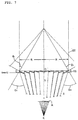
- a lens segment 12 a plurality of which compose a discontinuous light-beam condenser lens according to the present invention, is described below with reference to FIG. 5.
- a refractive surface 14 of the lens segment 12 is formed by part of cylindrical configuration having a predetermined curvature calculated by the "law of the crossed light".
- the lens segment 12 comprises the refractive surface 14 functioning as a condensing curved surface 16, and a stair-like incident-light surface 18.
- the mechanism of the discontinuous light-beam condenser lens comprising a plurality of the lens segments 12 according to the present invention is described below.
- the parallel light beams 20 pass through the stair-like incident-light surface 18 of the lens segment 12, the parallel light beams 20 straightforwardly permeate through the lens to the refracting lens surface 14 with little reflectance, because its incident angle is perpendicular to the incident-light surface 18 of the lens segment 12.
- the parallel light beams 20 arrive at the refractive surface 14 functioning as the condensing curved surface 16, refracted light beams 22 emerging from the refracting surface 14 are condensed onto a calculated condensing line K24 (a single line).
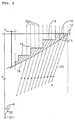
- FIG. 7 is a cross-sectional view of the discontinuous light-beam condenser lens 10 according to the present invention comprising the above-referred plural lens segments 12.
- Y is a center line of this discontinuous light-beam condenser 10, which is drawn perpendicular to the incident -light surface 18,
- O is an intersection of a center line Y and a horizontal line R intersecting at right angles, and
- A is an angle which center line Y forms with line X that links a point D and a condensing line K.
- ⁇ 1 should be less than a critical angle of full reflection thereof, although it depends on the refractive indexes of the medium and the lens.
- the refractive condensing curved surface of the discontinuous light-beam condenser lens according to the present invention is formed with gradient curved surface satisfying "multiple simultaneous equations based on the law of crossed light beams".
- ⁇ 1 OK for generating a four-dimensional unified-phase symmetrical angle is established.
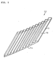
- FIG. 4 is a perspective view of the discontinuous light-beam condenser lens according to an embodiment of the present invention.
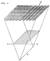
- FIG. 8 is a cross-sectional view and a flat view of the discontinuous light-beam condenser lens according to the present invention.
- the incident-light surface 18 is formed into a stair-like shape and the refractive surface 14 functions as the condensing curved surface 16.
- the lens segments having gradient curved surface formed by angles satisfying the above-described multiple simultaneous equations are disposed in this discontinuous light-beam condenser lens L.
- the discontinuous light-beam condenser lens of the present invention shown in FIG. 4 and FIG. 8 condenses light beams refracted via plural lens segments onto a single line, while respective lens segments condense light beams onto a single line by combination of a plurality of lens segments.
- Materials suitable for lens segments composing the discontinuous light-beam condenser lens according to the present invention are not particularly limited, as long as they have excellent light transmittance and transparency, light weight, and high mechanical strength.
- acrylic resin which has the above properties and excellent workability, can be preferably used.
- a fundamental requirement for the discontinuous light-beam condenser lens according to the present invention is that refracted light beams passing through the lens segments condensed at least onto a single line.
- Each of the lens segments may not always make contact with or be bonded with adjoining lens segments.
- Discontinuity on the level surface provides space between respective lens segments.
- discontinuity on the level surface avoids a variety of environmental problems that arise when the condenser unit is installed outdoors.
- the space between the outdoor lens segments may act as a ventilation passage to avoid wind pressure, and moreover, since rainwater flows through the space between the lens segments, there are not accumulated inside of the lens. Further, since birds can fly through the space, there is no fear that birds collide with the lens.
- the lens segments and the discontinuous condenser lens are fixed by providing means 26 for being linked to respective lens segment and supporting means 28 for supporting the discontinuous light-beam condenser lens comprising a plurality of lens segments being linked with each other.
- an angle of refracted surface is set according to distance from the condensing line, and then, based on the design in accordance with the angles, the condensing curved surface of individual lens segments is formed.
- a combination of lens segments is not particularly limited.
- light beams refracted from a plurality of lens segments are condensed onto a single line.
- refracted light beams are received on an arbitrary surface before being condensed onto a single line, they are condensed on a surface within a predetermined range. For example, if refracted light beams are received on surfaces comprising N - N' line of the cross-sectional view shown in FIG. 8, the light beams incident upon the discontinuous light-beam condenser lens of the present invention are condensed on the shaded area in FIG.
- the shaded area may be parallel with surfaces of the discontinuous light-beam condenser lens, otherwise it may be formed at a predetermined angle from the surfaces of the condenser lens. In this case, selections of temperature and illumination intensity can be made by adjusting the calculated lens segments, which makes it possible to secure an arbitrary area having a constant temperature.
- the arrangement of the above lens segments is not limited to a square formation as shown in FIG. 8, but a wide variety of forms including a circular form, polygonal forms, or such a form devoid of the center portion, or checkered pattern, may be selected in consideration of desirable temperature range or in accordance with the form of an area to be heated.
- a plurality of the discontinuous light-beam condenser lenses according to the present invention can be utilized in combination. It is also possible to intersect the condensing lines. In this case, high temperature and illumination intensity can be generated on surfaces including the intersection of the light beams. Further, it is also possible that an arbitrary surface closer to the lens than the area in which condensing lines are concentrated receives refracted light. Further, in order that their condensing lines can be provided in parallel, it is also possible to dispose a plurality of the discontinuous light-beam condenser lenses according to the present invention. Thus, the arrangement of the lens is not particularly limited.
- the thickness of the discontinuous light-beam condenser lens according to the present invention can be thinned down. Therefore, the condenser lens of the present invention is suitable for forming a large-scale condenser unit having strong wind-resistance and overcoming problems caused by rainwater and flying birds, and the like.
Landscapes
- Physics & Mathematics (AREA)
- Optics & Photonics (AREA)
- Engineering & Computer Science (AREA)
- General Physics & Mathematics (AREA)
- Life Sciences & Earth Sciences (AREA)
- Sustainable Development (AREA)
- Sustainable Energy (AREA)
- Toxicology (AREA)
- Health & Medical Sciences (AREA)
- Thermal Sciences (AREA)
- Chemical & Material Sciences (AREA)
- Combustion & Propulsion (AREA)
- Mechanical Engineering (AREA)
- General Engineering & Computer Science (AREA)
- Photovoltaic Devices (AREA)
- Optical Elements Other Than Lenses (AREA)
- Lenses (AREA)
Applications Claiming Priority (2)
| Application Number | Priority Date | Filing Date | Title |
|---|---|---|---|
| JP05235199A JP3432168B2 (ja) | 1999-03-01 | 1999-03-01 | 不連続線集光レンズ |
| JP5235199 | 1999-03-01 |
Publications (2)
| Publication Number | Publication Date |
|---|---|
| EP1033591A2 true EP1033591A2 (de) | 2000-09-06 |
| EP1033591A3 EP1033591A3 (de) | 2001-02-07 |
Family
ID=12912399
Family Applications (1)
| Application Number | Title | Priority Date | Filing Date |
|---|---|---|---|
| EP00104081A Withdrawn EP1033591A3 (de) | 1999-03-01 | 2000-02-28 | Diskontinuierliche Lichtstrahl-Kondenserlinse |
Country Status (5)
| Country | Link |
|---|---|
| US (1) | US6276817B1 (de) |
| EP (1) | EP1033591A3 (de) |
| JP (1) | JP3432168B2 (de) |
| CN (1) | CN1228649C (de) |
| WO (1) | WO2000052501A1 (de) |
Cited By (3)
| Publication number | Priority date | Publication date | Assignee | Title |
|---|---|---|---|---|
| US7115851B2 (en) | 2004-08-30 | 2006-10-03 | Yaoming Zhang | Heliostat device |
| US7203004B2 (en) | 2003-08-21 | 2007-04-10 | Yaoming Zhang | Directed reflection light collecting device with planar reflectors |
| WO2009115086A1 (de) * | 2008-03-19 | 2009-09-24 | Juri Koulechoff | Verfahren und linsenanordnung zur lichtkonzentration |
Families Citing this family (2)
| Publication number | Priority date | Publication date | Assignee | Title |
|---|---|---|---|---|
| CN101561115B (zh) * | 2009-04-08 | 2012-07-25 | 上海三思电子工程有限公司 | 一种led用超薄透镜的设计方法 |
| CN110107858B (zh) * | 2019-05-13 | 2024-03-22 | 华域视觉科技(上海)有限公司 | 车灯用聚光器设计方法和结构 |
Citations (1)
| Publication number | Priority date | Publication date | Assignee | Title |
|---|---|---|---|---|
| JPH06222581A (ja) * | 1993-01-22 | 1994-08-12 | Fuji Xerox Co Ltd | 電子写真感光体 |
Family Cites Families (8)
| Publication number | Priority date | Publication date | Assignee | Title |
|---|---|---|---|---|
| IL49997A (en) * | 1975-07-14 | 1978-08-31 | Nadaguchi Akira | Solar collector |
| JPS5626701U (de) * | 1979-08-04 | 1981-03-12 | ||
| US4848319A (en) * | 1985-09-09 | 1989-07-18 | Minnesota Mining And Manufacturing Company | Refracting solar energy concentrator and thin flexible Fresnel lens |
| JPH0648119B2 (ja) | 1986-03-27 | 1994-06-22 | 覚郎 八田 | 太陽炉に於ける超光熱集捉部装置 |
| GB2237122B (en) * | 1989-10-16 | 1993-10-27 | Combined Optical Ind Ltd | Improved fresnel lens |
| JPH06160610A (ja) * | 1989-12-26 | 1994-06-07 | Xerox Corp | 不連続多位相フレネルレンズ製造方法 |
| JP3392528B2 (ja) * | 1994-08-03 | 2003-03-31 | 政信 乾 | 線集光レンズ |
| JPH11125705A (ja) * | 1997-10-22 | 1999-05-11 | Masanobu Inui | 不連続点集光レンズ |
-
1999
- 1999-03-01 JP JP05235199A patent/JP3432168B2/ja not_active Expired - Lifetime
-
2000
- 2000-02-16 US US09/505,759 patent/US6276817B1/en not_active Expired - Lifetime
- 2000-02-28 EP EP00104081A patent/EP1033591A3/de not_active Withdrawn
- 2000-03-01 CN CNB008002533A patent/CN1228649C/zh not_active Expired - Fee Related
- 2000-03-01 WO PCT/JP2000/001214 patent/WO2000052501A1/ja not_active Ceased
Patent Citations (1)
| Publication number | Priority date | Publication date | Assignee | Title |
|---|---|---|---|---|
| JPH06222581A (ja) * | 1993-01-22 | 1994-08-12 | Fuji Xerox Co Ltd | 電子写真感光体 |
Cited By (3)
| Publication number | Priority date | Publication date | Assignee | Title |
|---|---|---|---|---|
| US7203004B2 (en) | 2003-08-21 | 2007-04-10 | Yaoming Zhang | Directed reflection light collecting device with planar reflectors |
| US7115851B2 (en) | 2004-08-30 | 2006-10-03 | Yaoming Zhang | Heliostat device |
| WO2009115086A1 (de) * | 2008-03-19 | 2009-09-24 | Juri Koulechoff | Verfahren und linsenanordnung zur lichtkonzentration |
Also Published As
| Publication number | Publication date |
|---|---|
| WO2000052501A1 (en) | 2000-09-08 |
| US6276817B1 (en) | 2001-08-21 |
| JP3432168B2 (ja) | 2003-08-04 |
| CN1296569A (zh) | 2001-05-23 |
| CN1228649C (zh) | 2005-11-23 |
| JP2000249805A (ja) | 2000-09-14 |
| EP1033591A3 (de) | 2001-02-07 |
Similar Documents
| Publication | Publication Date | Title |
|---|---|---|
| US4456783A (en) | Multielement optical panel | |
| US5936777A (en) | Axially-graded index-based couplers for solar concentrators | |
| US7395820B2 (en) | Receiver tube with receiver tubular jacket and parabolic trough collector containing same | |
| US4867514A (en) | Systems for deviating and (optionally) converging radiation | |
| JP2000147262A (ja) | 集光装置及びこれを利用した太陽光発電システム | |
| CN113219438A (zh) | 一种高精度mems激光雷达发射装置和方法 | |
| US5002379A (en) | Bypass mirrors | |
| JP2507712B2 (ja) | 薄く、しなやかなレンズ | |
| US6966661B2 (en) | Half-round total internal reflection magnifying prism | |
| US6840636B1 (en) | Solar diffusion loss compensator and collimator | |
| US6276817B1 (en) | Discontinuous light-beam condenser lens | |
| JP7017228B2 (ja) | 集光ユニット及び太陽光受光装置 | |
| CN101750754A (zh) | 视场分割型光学合成孔径成像系统 | |
| CN1226653C (zh) | 一种列阵型角扩束器 | |
| RU2613483C1 (ru) | Атермализованный объектив для ИК-области спектра | |
| CN101546032A (zh) | 被动式多功能球面(或柱面)聚光器 | |
| US20230392901A1 (en) | Wide-Angle Seeker | |
| RU2442082C2 (ru) | Способ концентрации солнечной энергии | |
| EP1810345B1 (de) | Optischer konzentrator | |
| RU2188987C2 (ru) | Концентратор солнечной энергии | |
| CN2639917Y (zh) | 一种列阵型角扩束器 | |
| RU2576739C2 (ru) | Солнечный модуль с концентратором | |
| EP0016245A1 (de) | System zum Sammeln von Sonnenenergie | |
| US6587286B1 (en) | Circular prism light capacitor | |
| KR101130765B1 (ko) | 측면 태양광 집광기 |
Legal Events
| Date | Code | Title | Description |
|---|---|---|---|
| PUAI | Public reference made under article 153(3) epc to a published international application that has entered the european phase |
Free format text: ORIGINAL CODE: 0009012 |
|
| AK | Designated contracting states |
Kind code of ref document: A2 Designated state(s): DE FR GB IT |
|
| AX | Request for extension of the european patent |
Free format text: AL;LT;LV;MK;RO;SI |
|
| PUAL | Search report despatched |
Free format text: ORIGINAL CODE: 0009013 |
|
| RIC1 | Information provided on ipc code assigned before grant |
Free format text: 7F 24J 2/08 A, 7G 02B 3/08 B |
|
| AK | Designated contracting states |
Kind code of ref document: A3 Designated state(s): AT BE CH CY DE DK ES FI FR GB GR IE IT LI LU MC NL PT SE |
|
| AX | Request for extension of the european patent |
Free format text: AL;LT;LV;MK;RO;SI |
|
| 17P | Request for examination filed |
Effective date: 20010803 |
|
| AKX | Designation fees paid |
Free format text: DE FR GB IT |
|
| GRAP | Despatch of communication of intention to grant a patent |
Free format text: ORIGINAL CODE: EPIDOSNIGR1 |
|
| STAA | Information on the status of an ep patent application or granted ep patent |
Free format text: STATUS: THE APPLICATION IS DEEMED TO BE WITHDRAWN |
|
| 18D | Application deemed to be withdrawn |
Effective date: 20030902 |