EP1033506B1 - Agencement structurel réducteur de choc - Google Patents
Agencement structurel réducteur de choc Download PDFInfo
- Publication number
- EP1033506B1 EP1033506B1 EP00400561A EP00400561A EP1033506B1 EP 1033506 B1 EP1033506 B1 EP 1033506B1 EP 00400561 A EP00400561 A EP 00400561A EP 00400561 A EP00400561 A EP 00400561A EP 1033506 B1 EP1033506 B1 EP 1033506B1
- Authority
- EP
- European Patent Office
- Prior art keywords
- microgranules
- shock
- source
- cells
- equipment
- Prior art date
- Legal status (The legal status is an assumption and is not a legal conclusion. Google has not performed a legal analysis and makes no representation as to the accuracy of the status listed.)
- Expired - Lifetime
Links
- 230000035939 shock Effects 0.000 title claims abstract description 65
- 230000002093 peripheral effect Effects 0.000 claims description 8
- 239000004005 microsphere Substances 0.000 claims description 5
- 239000011521 glass Substances 0.000 claims description 4
- 230000002238 attenuated effect Effects 0.000 claims description 2
- 230000001413 cellular effect Effects 0.000 claims 3
- 210000004027 cell Anatomy 0.000 abstract description 45
- 210000003850 cellular structure Anatomy 0.000 abstract description 2
- 241000264877 Hippospongia communis Species 0.000 description 22
- 230000007246 mechanism Effects 0.000 description 10
- 239000000463 material Substances 0.000 description 8
- 230000001133 acceleration Effects 0.000 description 5
- 238000013016 damping Methods 0.000 description 5
- 230000008901 benefit Effects 0.000 description 4
- 230000004044 response Effects 0.000 description 4
- 238000001228 spectrum Methods 0.000 description 4
- 230000000712 assembly Effects 0.000 description 3
- 238000000429 assembly Methods 0.000 description 3
- 230000009467 reduction Effects 0.000 description 3
- 239000006096 absorbing agent Substances 0.000 description 2
- 238000010586 diagram Methods 0.000 description 2
- 230000002123 temporal effect Effects 0.000 description 2
- 230000004584 weight gain Effects 0.000 description 2
- 235000019786 weight gain Nutrition 0.000 description 2
- 241000257303 Hymenoptera Species 0.000 description 1
- 108091092878 Microsatellite Proteins 0.000 description 1
- 238000010521 absorption reaction Methods 0.000 description 1
- XAGFODPZIPBFFR-UHFFFAOYSA-N aluminium Chemical compound [Al] XAGFODPZIPBFFR-UHFFFAOYSA-N 0.000 description 1
- 229910052782 aluminium Inorganic materials 0.000 description 1
- 230000005540 biological transmission Effects 0.000 description 1
- 230000008859 change Effects 0.000 description 1
- 230000008878 coupling Effects 0.000 description 1
- 238000010168 coupling process Methods 0.000 description 1
- 238000005859 coupling reaction Methods 0.000 description 1
- 238000006073 displacement reaction Methods 0.000 description 1
- 229920001971 elastomer Polymers 0.000 description 1
- 239000000806 elastomer Substances 0.000 description 1
- 239000013536 elastomeric material Substances 0.000 description 1
- 239000012530 fluid Substances 0.000 description 1
- 239000006260 foam Substances 0.000 description 1
- 238000000034 method Methods 0.000 description 1
- 238000005192 partition Methods 0.000 description 1
- 230000008569 process Effects 0.000 description 1
- 230000001902 propagating effect Effects 0.000 description 1
- 230000035945 sensitivity Effects 0.000 description 1
- 125000006850 spacer group Chemical group 0.000 description 1
Images


Classifications
-
- F—MECHANICAL ENGINEERING; LIGHTING; HEATING; WEAPONS; BLASTING
- F16—ENGINEERING ELEMENTS AND UNITS; GENERAL MEASURES FOR PRODUCING AND MAINTAINING EFFECTIVE FUNCTIONING OF MACHINES OR INSTALLATIONS; THERMAL INSULATION IN GENERAL
- F16F—SPRINGS; SHOCK-ABSORBERS; MEANS FOR DAMPING VIBRATION
- F16F7/00—Vibration-dampers; Shock-absorbers
- F16F7/01—Vibration-dampers; Shock-absorbers using friction between loose particles, e.g. sand
-
- F—MECHANICAL ENGINEERING; LIGHTING; HEATING; WEAPONS; BLASTING
- F16—ENGINEERING ELEMENTS AND UNITS; GENERAL MEASURES FOR PRODUCING AND MAINTAINING EFFECTIVE FUNCTIONING OF MACHINES OR INSTALLATIONS; THERMAL INSULATION IN GENERAL
- F16F—SPRINGS; SHOCK-ABSORBERS; MEANS FOR DAMPING VIBRATION
- F16F1/00—Springs
- F16F1/36—Springs made of rubber or other material having high internal friction, e.g. thermoplastic elastomers
- F16F1/37—Springs made of rubber or other material having high internal friction, e.g. thermoplastic elastomers of foam-like material, i.e. microcellular material, e.g. sponge rubber
-
- Y—GENERAL TAGGING OF NEW TECHNOLOGICAL DEVELOPMENTS; GENERAL TAGGING OF CROSS-SECTIONAL TECHNOLOGIES SPANNING OVER SEVERAL SECTIONS OF THE IPC; TECHNICAL SUBJECTS COVERED BY FORMER USPC CROSS-REFERENCE ART COLLECTIONS [XRACs] AND DIGESTS
- Y10—TECHNICAL SUBJECTS COVERED BY FORMER USPC
- Y10T—TECHNICAL SUBJECTS COVERED BY FORMER US CLASSIFICATION
- Y10T428/00—Stock material or miscellaneous articles
- Y10T428/23—Sheet including cover or casing
- Y10T428/234—Sheet including cover or casing including elements cooperating to form cells
- Y10T428/236—Honeycomb type cells extend perpendicularly to nonthickness layer
-
- Y—GENERAL TAGGING OF NEW TECHNOLOGICAL DEVELOPMENTS; GENERAL TAGGING OF CROSS-SECTIONAL TECHNOLOGIES SPANNING OVER SEVERAL SECTIONS OF THE IPC; TECHNICAL SUBJECTS COVERED BY FORMER USPC CROSS-REFERENCE ART COLLECTIONS [XRACs] AND DIGESTS
- Y10—TECHNICAL SUBJECTS COVERED BY FORMER USPC
- Y10T—TECHNICAL SUBJECTS COVERED BY FORMER US CLASSIFICATION
- Y10T428/00—Stock material or miscellaneous articles
- Y10T428/24—Structurally defined web or sheet [e.g., overall dimension, etc.]
- Y10T428/24149—Honeycomb-like
-
- Y—GENERAL TAGGING OF NEW TECHNOLOGICAL DEVELOPMENTS; GENERAL TAGGING OF CROSS-SECTIONAL TECHNOLOGIES SPANNING OVER SEVERAL SECTIONS OF THE IPC; TECHNICAL SUBJECTS COVERED BY FORMER USPC CROSS-REFERENCE ART COLLECTIONS [XRACs] AND DIGESTS
- Y10—TECHNICAL SUBJECTS COVERED BY FORMER USPC
- Y10T—TECHNICAL SUBJECTS COVERED BY FORMER US CLASSIFICATION
- Y10T428/00—Stock material or miscellaneous articles
- Y10T428/24—Structurally defined web or sheet [e.g., overall dimension, etc.]
- Y10T428/24149—Honeycomb-like
- Y10T428/24157—Filled honeycomb cells [e.g., solid substance in cavities, etc.]
-
- Y—GENERAL TAGGING OF NEW TECHNOLOGICAL DEVELOPMENTS; GENERAL TAGGING OF CROSS-SECTIONAL TECHNOLOGIES SPANNING OVER SEVERAL SECTIONS OF THE IPC; TECHNICAL SUBJECTS COVERED BY FORMER USPC CROSS-REFERENCE ART COLLECTIONS [XRACs] AND DIGESTS
- Y10—TECHNICAL SUBJECTS COVERED BY FORMER USPC
- Y10T—TECHNICAL SUBJECTS COVERED BY FORMER US CLASSIFICATION
- Y10T428/00—Stock material or miscellaneous articles
- Y10T428/29—Coated or structually defined flake, particle, cell, strand, strand portion, rod, filament, macroscopic fiber or mass thereof
- Y10T428/2982—Particulate matter [e.g., sphere, flake, etc.]
Definitions
- the invention relates to structural arrangements which incorporate honeycomb cell support elements for assembly equipment materials subjected to shocks. It concerns more particularly those where it is necessary to reduce the level of shock transmitted from a source to at least one equipment through the layout.
- certain hardware assemblies such as satellites or their launchers
- satellites and launchers often have numerous mechanisms, in particular pyrotechnics, which allow ignition, move, develop, separate or activate various pieces of equipment that are the source of significant shocks. These are in particular the mechanisms for cutting out launchers or stacking systems for payloads which tend to be more and more powerful. This therefore leads to the search for solutions allowing reduce the shock levels to which assemblies are likely to be subjected and more particularly their shock-sensitive equipment.
- shocks at their level For example by incorporating an elastomeric material in place for absorb some of the shock waves.
- a shock power limitation in a ratio 2 beyond 1000 Hz, is for example obtained by this means, in the case of a satellite antenna clearance subsystem and solar panels.
- the invention therefore provides a structural arrangement intended to ensure a reduction of the level of shock transmitted from a source to at least one piece of equipment in a material assembly where the arrangement incorporates one or more elements of support, with honeycomb cells, carrying the equipment to be protected from impact and / or the source, characterized in that said or at least one of said support elements is filled with rigid microgranules in contact so that the vibratory waves shock and / or source are attenuated by the friction generated by the setting sliding microgranules on top of each other.
- microgranules are free to move, slide, rub and this are these phenomena that create the attenuation of the propagating vibrational waves in the structure during pyrotechnic shocks.
- this arrangement comprises at least a support member having honeycomb cells which are filled with rigid microgranules.
- the arrangement comprises at least one support member including honeycomb cells filled with microgranules which is mounted between an element carrying a shock source and a element carrying equipment to protect from impact.
- the arrangement comprises at less equipment to be protected from impact and / or a shock source fitted, or mounted, on a support element whose cells are filled with microgranules.
- the arrangement comprises at least one honeycomb cell support member having cells filled with microgranules in a zone or several delimited zone (s) each consisting of a main part, to the right of which is mounted a equipment to be protected, and a peripheral extension which borders externally this main part.
- the arrangement comprises at least one honeycomb cell support member having cells filled with microgranules in a zone or several delimited zone (s) each consisting of a main part, to the right of which is mounted a source, and a peripheral extension which borders this main part.
- the rigid microgranules filling the honeycomb cells are compacted and have no not the possibility of play within the support element.
- the rigid microgranules filling the honeycomb cells are formed of hollow microspheres, possibly made of glass.
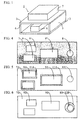
- Figure 1 shows a simplified example of a structural support arrangement for hardware assembly, according to the invention.
- Figure 2 presents two diagrams showing the times of the reference shock accelerations that are measured at the end of two beams, one with empty cells and the other according to the invention.
- Figure 3 shows a diagram with two curves which show the shock response spectra of the accelerations, due to a reference shock, which are measured at the end of two beams, one with empty cells and the other according to the invention.
- FIGS 4, 5 and 6 show three examples of arrangement structural according to the invention.
- the structural arrangement according to the invention is in particular intended to be implemented works to protect against impact one, or the equipment of an assembly which is for example a satellite, a launcher or another aircraft.
- mechanisms are conventionally provided mainly or incidentally producing shocks and in particular pyrotechnic mechanisms in the equipment assemblies as mentioned above. These mechanisms are more and more generally brought to border with the other equipment in the set that includes them and that we are looking for the most often to be concentrated in as little space as possible. Some of the equipment, especially electronic equipment, can be relatively fragile and therefore seeks to limit the shock levels transmitted to them.
- mechanism constituting a shock source and equipment, which one wishes to protect are part of the same material set, they are generally carried by through a support structure, common to everything that makes up the whole, or more particularly by a structural arrangement which constitutes a part of this common support structure.
- FIG. 1 An example of such a structural arrangement 1 is shown diagrammatically in FIG. 1, it is assumed to consist of support elements 2, 3, 4, 5, here assembled in the form of a box.
- the latter has a lower level where a mechanism is mounted constituting a shock source 6, for example a pusher, a valve, a system cutting.
- Equipment 7 is assumed to be placed at the upper level of the box and it receives any shock transmitted to the caisson by the source. In the schematic example proposed this transmission takes place from source 6 to equipment 7, via the elements support 2 to 5.
- At least some of the support elements of the structural arrangement 1 may be produced under the shape of panels, honeycomb, each consisting of a cellular structure metallic, usually planar, the cells of which are contiguously arranged are closed to at least one of their ends by a thin plate, for example metallic, forming a skin which covers them.
- the curves referenced "Ref" in Figures 2 and 3 respectively show the temporal and the shock response spectrum of the accelerations measured at the extremity non-recessed of a recessed support element, of the rectangular beam type, subject at half-sine shock at 800 g and duration 0.3 ms.
- This element is here assumed to be an aluminum beam whose honeycomb cells arranged vertically are closed by a thin plate, called skin, at each of their ends.
- skin a thin plate
- microgranules rigid, low rigid density.
- these microgranules can be produced in the form of hollow microgranules which are placed in each cell closed at one end by a first skin.
- the microgranules are packed and have no possibility of play, as soon as the cells have were closed at their other end by a second skin. This settlement favors the friction between the microspheres during the passage of waves and thus allows further improve the desired attenuation.
- the microgranules are for example made in the form of hollow microspheres possibly made of glass to have good rigidity.
- the specific mass obtained with this filling material is commonly of the order of 100 to 200 kg / m 3 .
- a filling material is provided which consists of microgranules whose dimensional characteristics are heterogeneous, with for example a maximum dimension of the order of 500 microns. A minimum dimension is also likely to be provided. It is for example chosen to be greater than microperforations, of the order of 100 microns, conventionally present in the walls of honeycomb cells, so as to avoid any possibility of displacement of microgranules from one cell to another. It is also possible to ensure containment of the smallest microgranules in one honeycomb cell to another by other means, for example by interposition of a foam with open cells.
- the curves referenced "Nida + microS" in Figures 2 and 3 show respectively the temporal and the spectrum of response to the shock of the accelerations measured at the end of a support element under the conditions described above.
- This element is assumed to be identical in structure to the previous one, but has its cells filled with glass microspheres under the conditions provided for the invention.
- the filling causes an increase in the mass of the support element of the order of 25%, it also results in an evolution of the time maximum of the measured acceleration which goes from 500 to 300g, as we see it by comparing the curves "Ref" and "Nida + microS" in Figure 2.
- a attenuation of the shock response spectrum is practically obtained at all frequencies with a particular efficiency of the order of 6dB between 1000 and 10000 Hz.
- the invention allows the realization of structural arrangements in which are provided one or more support elements with honeycomb cells filled with rigid and possibly hollow microgranules. As indicated above in a particular embodiment these microgranules are packed, without play, inside cells.
- Figures 4 to 6 show structural arrangements or at least one shock source and at least one equipment to be protected are mounted on the same support element 7, 7A or 7B, having cells, in honeycombs, filled with microgranules, as defined above.
- a mechanism constituting a shock source 8 is assumed to be mounted on the support element 7, preferably at one end of this support.
- Equipment 9, 9 'and 9 are also mounted on this element 7 and they receive the shocks transmitted to it by the source 8. These shocks reach them so mainly through cells filled with microgranules which provide a reduction in the level of shock transmitted to the equipment.
- the support element does not includes a shock source 8A and three separate pieces of equipment 9A, to be protected from shock waves transmitted by the support element from the shock source.
- a individual cushioning zone composed of a main part and an extension peripheral, is then fitted for each piece of equipment 9A on the element of support 7A. Only the peripheral extension 11A, shown in gray, of each zone shock absorber is illustrated in Figure 5, insofar as the main part hidden by the equipment she wears.
- Each damping zone composed of cells filled with microgranules is therefore separated by empty cells from any other damping zone of the same support element.
- the solution proposed above is also suitable, if several equipment, each mounted in front of an intermediate zone with cells filled with microgranules of a support element, are to be protected from several sources including shock waves are likely to be transmitted to equipment, via their element of support.
- a damping zone is then arranged for the shock source 8B on the support element 7B by filling the cells, by means of microgranules, in part of this element.
- this area shock absorber consists of a main part, to the right of which is mounted the shock source 8B, and a peripheral extension 12B which borders externally this main part.
- One of the advantages of solutions providing one or more damping zones, as defined above, is to minimize overweight driven by the filling of cells.
- the filling, selective or global, of a support element composed of honeycomb cells, using microgranules has the advantage of partition the volume of material used for depreciation into a large number of elementary volumes practically independent of each other.
- the reduction in shock level obtained is the consequence of the use of complex phenomena relating in particular to the fluid behavior of the medium, to the fluid-structure coupling, absorption of the granular medium, dry friction and to non-linearities. To all this is also added the impedance breaks in the case support elements whose filling is localized.
- One of the advantages provided by the invention is to allow an approach called parallel, compared to the serial approach associated with the use of an elastomer intermediate. There is no change in the rigidity of the support element and the structural arrangement which comprises it. There is also no intrusion additional due to cell filling, since this filling only occupies previously unused volumes.
Landscapes
- Engineering & Computer Science (AREA)
- General Engineering & Computer Science (AREA)
- Mechanical Engineering (AREA)
- Vibration Dampers (AREA)
- Vehicle Interior And Exterior Ornaments, Soundproofing, And Insulation (AREA)
- Basic Packing Technique (AREA)
Description
Claims (8)
- Agencement structurel destiné à assurer une réduction du niveau de choc transmis depuis une source (6, 8, 8A, 8B) à au moins un équipement (7,9, 9', 9")) dans un ensemble matériel où l'agencement incorpore un ou des éléments de support (2, 3, 4, 5, 7, 7A) à cellules en nid d'abeilles portant l'équipement à protéger des chocs et/ou la source, caractérisé en ce que ledit ou au moins l'un desdits éléments de support (2, 3, 4, 5) est rempli de microgranules rigides en contact de manière à ce que les ondes vibratoires des chocs et/ou de la source soient atténuées par les frottements générés par la mise en glissement des microgranules les uns sur les autres.
- Agencement structurel, selon la revendication 1, dans lequel au moins un élément de support (4, 5), comportant des cellules en nid d'abeilles remplies de microgranules, est monté entre un élément (2) portant une source de choc et un élément (3) portant un équipement à protéger des chocs.
- Agencement structurel, selon la revendication 1, qui comporte au moins l'équipement (9, 9' ou 9") à protéger des chocs et/ou une source de choc (8) monté(e), ou montés, sur l'élément de support (7) supportant également la source de choc dont les cellules sont remplies de microgranules.
- Agencement structurel, selon la revendication 1, dans lequel au moins l'élément de support (7A) à cellules en nid d'abeilles comporte des cellules remplies de microgranules dans une zone ou plusieurs zones délimitées constituées chacune d'une partie principale au droit de laquelle est monté un équipement à protéger (9A) et d'une extension périphérique (11A) qui borde extérieurement cette partie principale.
- Agencement structurel, selon la revendication 1, dans lequel au moins l'élément de support (7A) à cellules en nid d'abeilles comporte des cellules remplies de microgranules dans une zone ou plusieurs zones délimitées constituées chacune d'une partie principale au droit de laquelle est montée une source (8B) et d'une extension périphérique (12B) qui borde cette partie principale.
- Agencement structurel, selon l'une des revendications 1 à 5, dans lequel les microgranules rigides remplissant les cellules en nid d'abeille ont des caractéristiques dimensionnelles hétérogènes.
- Agencement structurel, selon l'une des revendications 1 à 5, dans lequel les microgranules rigides remplissant les cellules en nid d'abeille sont tassés et n'ont pas la possibilité de jeu au sein de l'élément de support.
- Agencement structurel, selon l'une des revendications 1 à 7, dans lequel les microgranules rigides remplissant les cellules en nid d'abeille sont formés de microsphères creuses, éventuellement réalisées en verre.
Applications Claiming Priority (2)
| Application Number | Priority Date | Filing Date | Title |
|---|---|---|---|
| FR9902684 | 1999-03-04 | ||
| FR9902684A FR2790526B1 (fr) | 1999-03-04 | 1999-03-04 | Agencement structurel reducteur de choc |
Publications (2)
| Publication Number | Publication Date |
|---|---|
| EP1033506A1 EP1033506A1 (fr) | 2000-09-06 |
| EP1033506B1 true EP1033506B1 (fr) | 2004-08-18 |
Family
ID=9542813
Family Applications (1)
| Application Number | Title | Priority Date | Filing Date |
|---|---|---|---|
| EP00400561A Expired - Lifetime EP1033506B1 (fr) | 1999-03-04 | 2000-03-02 | Agencement structurel réducteur de choc |
Country Status (6)
| Country | Link |
|---|---|
| US (1) | US6500517B1 (fr) |
| EP (1) | EP1033506B1 (fr) |
| AT (1) | ATE274151T1 (fr) |
| CA (1) | CA2299660C (fr) |
| DE (1) | DE60013004T2 (fr) |
| FR (1) | FR2790526B1 (fr) |
Families Citing this family (2)
| Publication number | Priority date | Publication date | Assignee | Title |
|---|---|---|---|---|
| GB2539228B (en) * | 2015-06-10 | 2017-07-26 | Fergusson's Advanced Composite Tech Ltd | A method of making a composite structure |
| CN114893524B (zh) * | 2022-04-29 | 2024-04-19 | 厦门振为科技有限公司 | 一种火工分离用高效降冲击装置 |
Family Cites Families (8)
| Publication number | Priority date | Publication date | Assignee | Title |
|---|---|---|---|---|
| FR2212011A5 (fr) * | 1972-12-21 | 1974-07-19 | Lincrusta | |
| US4193829A (en) * | 1977-03-16 | 1980-03-18 | The United States Of America As Represented By The Administrator Of The National Aeronautics And Space Administration | Process for the manufacture of low density bis-maleimide-carbon microballoon composites |
| US4330494A (en) * | 1978-09-13 | 1982-05-18 | Sekisui Kagaku Kogyo Kabushiki Kaisha | Reinforced foamed resin structural material and process for manufacturing the same |
| JPS6051750A (ja) * | 1983-08-30 | 1985-03-23 | Murata Mfg Co Ltd | 防振複合体 |
| FR2631668B2 (fr) * | 1988-01-15 | 1993-11-12 | Hutchinson | Supports elastiques de suspension |
| US4965097A (en) * | 1989-01-11 | 1990-10-23 | Reynolds Consumer Products, Inc. | Texturized cell material for confinement of concrete and earth materials |
| US5041472A (en) * | 1990-12-19 | 1991-08-20 | Hughes Aircraft Company | Syntactic foam energy absorber |
| US6221445B1 (en) * | 1999-07-20 | 2001-04-24 | U.S. Greentech, Inc. | Composite artificial turf structure with shock absorption and drainage |
-
1999
- 1999-03-04 FR FR9902684A patent/FR2790526B1/fr not_active Expired - Fee Related
-
2000
- 2000-02-29 CA CA002299660A patent/CA2299660C/fr not_active Expired - Fee Related
- 2000-03-01 US US09/516,514 patent/US6500517B1/en not_active Expired - Fee Related
- 2000-03-02 EP EP00400561A patent/EP1033506B1/fr not_active Expired - Lifetime
- 2000-03-02 DE DE60013004T patent/DE60013004T2/de not_active Expired - Lifetime
- 2000-03-02 AT AT00400561T patent/ATE274151T1/de not_active IP Right Cessation
Also Published As
| Publication number | Publication date |
|---|---|
| EP1033506A1 (fr) | 2000-09-06 |
| FR2790526A1 (fr) | 2000-09-08 |
| US6500517B1 (en) | 2002-12-31 |
| DE60013004D1 (de) | 2004-09-23 |
| FR2790526B1 (fr) | 2001-10-12 |
| CA2299660C (fr) | 2008-08-12 |
| ATE274151T1 (de) | 2004-09-15 |
| CA2299660A1 (fr) | 2000-09-04 |
| DE60013004T2 (de) | 2005-01-27 |
Similar Documents
| Publication | Publication Date | Title |
|---|---|---|
| EP2304380B1 (fr) | Dispositif de protection de plancher pour une cabine de vehicule | |
| EP1821061B1 (fr) | Dispositif de protection d'un plancher véhicule | |
| FR2618823A1 (fr) | Procede pour limiter la reaction d'une structure vis-a-vis des perturbations exterieures, et appareil pour sa mise en oeuvre | |
| EP0324693B1 (fr) | Supports elastiques de suspension | |
| EP1192404B1 (fr) | Dispositif de protection d'une paroi | |
| FR2829546A1 (fr) | Barre de liaison a absorption d'energie, et son application comme barre de suspension de boite de transmission pour giravion | |
| FR3095023A1 (fr) | Metamateriau pour le filtrage des vibrations et piece isolante realisee avec ledit metamateriau | |
| WO2015117868A1 (fr) | Panneau insonorisant | |
| CA2299660C (fr) | Agencement structurel reducteur de choc | |
| WO2021104998A1 (fr) | Dispositif de protection de structures statiques ou mobiles, terrestres, nautiques ou aeriennes contre le souffle d'une explosion ou detonation et les projections de matiere associees | |
| FR2971233A1 (fr) | Substrat amortissant pour panneau structurel de satellite | |
| FR2885583A1 (fr) | Dispositif de renforcement d'un element creux de carrosserie et procede correspondant | |
| EP1005049A1 (fr) | Dispositif amortisseur de chocs pour conteneurs de matières radioactives | |
| EP2091786B1 (fr) | Dispositif de protection pour vehicule automobile | |
| EP1649189A1 (fr) | Procede et dispositif de filtrage et d'attenuation des vibrations | |
| FR2800351A1 (fr) | Attenuateur de chocs pour pied de gerbage | |
| FR2595146A1 (fr) | Structure suspendue pour coupler des sources sismiques aux parois d'un forage | |
| FR2941191A1 (fr) | Ecran acoustique. | |
| FR2791626A1 (fr) | Element de structure a amortisseur de choc | |
| US12562143B2 (en) | Unit cell and structural panel assemblies with enhanced impact and noise absorption characteristics | |
| FR2895963A1 (fr) | Vehicule automobile du type decouvrable comprenant au moins un arceau de securite actif utilise comme batteur. | |
| CN221023959U (zh) | 一种具有液压让压功能的防岩爆构件 | |
| Nersessian et al. | NEGATIVE STIFFNESS HONEYCOMBS FOR BLAST MITIGATION PANELS | |
| EP0495715A2 (fr) | Panneau résistant aux chocs par absorption d'énergie | |
| EP3172087B1 (fr) | Dispositif de voie basse pour véhicule automobile |
Legal Events
| Date | Code | Title | Description |
|---|---|---|---|
| PUAI | Public reference made under article 153(3) epc to a published international application that has entered the european phase |
Free format text: ORIGINAL CODE: 0009012 |
|
| AK | Designated contracting states |
Kind code of ref document: A1 Designated state(s): AT BE CH CY DE DK ES FI FR GB GR IE IT LI LU MC NL PT SE |
|
| AX | Request for extension of the european patent |
Free format text: AL;LT;LV;MK;RO;SI |
|
| 17P | Request for examination filed |
Effective date: 20010306 |
|
| AKX | Designation fees paid |
Free format text: AT BE CH CY DE DK ES FI FR GB GR IE IT LI LU MC NL PT SE |
|
| 17Q | First examination report despatched |
Effective date: 20030416 |
|
| GRAP | Despatch of communication of intention to grant a patent |
Free format text: ORIGINAL CODE: EPIDOSNIGR1 |
|
| RIN1 | Information on inventor provided before grant (corrected) |
Inventor name: YOUSSEFI, THIERRY Inventor name: BREVART, BERTRAND Inventor name: BODIN, EMMANUEL |
|
| GRAS | Grant fee paid |
Free format text: ORIGINAL CODE: EPIDOSNIGR3 |
|
| GRAA | (expected) grant |
Free format text: ORIGINAL CODE: 0009210 |
|
| AK | Designated contracting states |
Kind code of ref document: B1 Designated state(s): AT BE CH CY DE DK ES FI FR GB GR IE IT LI LU MC NL PT SE |
|
| PG25 | Lapsed in a contracting state [announced via postgrant information from national office to epo] |
Ref country code: FI Free format text: LAPSE BECAUSE OF FAILURE TO SUBMIT A TRANSLATION OF THE DESCRIPTION OR TO PAY THE FEE WITHIN THE PRESCRIBED TIME-LIMIT Effective date: 20040818 Ref country code: IE Free format text: LAPSE BECAUSE OF FAILURE TO SUBMIT A TRANSLATION OF THE DESCRIPTION OR TO PAY THE FEE WITHIN THE PRESCRIBED TIME-LIMIT Effective date: 20040818 Ref country code: AT Free format text: LAPSE BECAUSE OF FAILURE TO SUBMIT A TRANSLATION OF THE DESCRIPTION OR TO PAY THE FEE WITHIN THE PRESCRIBED TIME-LIMIT Effective date: 20040818 |
|
| REG | Reference to a national code |
Ref country code: GB Ref legal event code: FG4D Free format text: NOT ENGLISH |
|
| REG | Reference to a national code |
Ref country code: CH Ref legal event code: EP |
|
| GBT | Gb: translation of ep patent filed (gb section 77(6)(a)/1977) |
Effective date: 20040818 |
|
| REG | Reference to a national code |
Ref country code: IE Ref legal event code: FG4D Free format text: FRENCH |
|
| REF | Corresponds to: |
Ref document number: 60013004 Country of ref document: DE Date of ref document: 20040923 Kind code of ref document: P |
|
| PG25 | Lapsed in a contracting state [announced via postgrant information from national office to epo] |
Ref country code: SE Free format text: LAPSE BECAUSE OF FAILURE TO SUBMIT A TRANSLATION OF THE DESCRIPTION OR TO PAY THE FEE WITHIN THE PRESCRIBED TIME-LIMIT Effective date: 20041118 Ref country code: DK Free format text: LAPSE BECAUSE OF FAILURE TO SUBMIT A TRANSLATION OF THE DESCRIPTION OR TO PAY THE FEE WITHIN THE PRESCRIBED TIME-LIMIT Effective date: 20041118 Ref country code: GR Free format text: LAPSE BECAUSE OF FAILURE TO SUBMIT A TRANSLATION OF THE DESCRIPTION OR TO PAY THE FEE WITHIN THE PRESCRIBED TIME-LIMIT Effective date: 20041118 |
|
| PG25 | Lapsed in a contracting state [announced via postgrant information from national office to epo] |
Ref country code: ES Free format text: LAPSE BECAUSE OF FAILURE TO SUBMIT A TRANSLATION OF THE DESCRIPTION OR TO PAY THE FEE WITHIN THE PRESCRIBED TIME-LIMIT Effective date: 20041129 |
|
| PG25 | Lapsed in a contracting state [announced via postgrant information from national office to epo] |
Ref country code: CY Free format text: LAPSE BECAUSE OF FAILURE TO SUBMIT A TRANSLATION OF THE DESCRIPTION OR TO PAY THE FEE WITHIN THE PRESCRIBED TIME-LIMIT Effective date: 20050302 Ref country code: LU Free format text: LAPSE BECAUSE OF NON-PAYMENT OF DUE FEES Effective date: 20050302 |
|
| REG | Reference to a national code |
Ref country code: IE Ref legal event code: FD4D |
|
| PG25 | Lapsed in a contracting state [announced via postgrant information from national office to epo] |
Ref country code: BE Free format text: LAPSE BECAUSE OF NON-PAYMENT OF DUE FEES Effective date: 20050331 Ref country code: LI Free format text: LAPSE BECAUSE OF NON-PAYMENT OF DUE FEES Effective date: 20050331 Ref country code: MC Free format text: LAPSE BECAUSE OF NON-PAYMENT OF DUE FEES Effective date: 20050331 Ref country code: CH Free format text: LAPSE BECAUSE OF NON-PAYMENT OF DUE FEES Effective date: 20050331 |
|
| PLBE | No opposition filed within time limit |
Free format text: ORIGINAL CODE: 0009261 |
|
| STAA | Information on the status of an ep patent application or granted ep patent |
Free format text: STATUS: NO OPPOSITION FILED WITHIN TIME LIMIT |
|
| 26N | No opposition filed |
Effective date: 20050519 |
|
| BERE | Be: lapsed |
Owner name: *ALCATEL Effective date: 20050331 |
|
| REG | Reference to a national code |
Ref country code: CH Ref legal event code: PL |
|
| REG | Reference to a national code |
Ref country code: FR Ref legal event code: CD |
|
| BERE | Be: lapsed |
Owner name: *ALCATEL Effective date: 20050331 |
|
| PG25 | Lapsed in a contracting state [announced via postgrant information from national office to epo] |
Ref country code: PT Free format text: LAPSE BECAUSE OF NON-PAYMENT OF DUE FEES Effective date: 20050118 |
|
| PGFP | Annual fee paid to national office [announced via postgrant information from national office to epo] |
Ref country code: NL Payment date: 20110317 Year of fee payment: 12 Ref country code: IT Payment date: 20110315 Year of fee payment: 12 |
|
| PGFP | Annual fee paid to national office [announced via postgrant information from national office to epo] |
Ref country code: GB Payment date: 20110302 Year of fee payment: 12 Ref country code: DE Payment date: 20110223 Year of fee payment: 12 |
|
| REG | Reference to a national code |
Ref country code: NL Ref legal event code: V1 Effective date: 20121001 |
|
| GBPC | Gb: european patent ceased through non-payment of renewal fee |
Effective date: 20120302 |
|
| REG | Reference to a national code |
Ref country code: DE Ref legal event code: R119 Ref document number: 60013004 Country of ref document: DE Effective date: 20121002 |
|
| PG25 | Lapsed in a contracting state [announced via postgrant information from national office to epo] |
Ref country code: GB Free format text: LAPSE BECAUSE OF NON-PAYMENT OF DUE FEES Effective date: 20120302 |
|
| PG25 | Lapsed in a contracting state [announced via postgrant information from national office to epo] |
Ref country code: IT Free format text: LAPSE BECAUSE OF NON-PAYMENT OF DUE FEES Effective date: 20120302 |
|
| PG25 | Lapsed in a contracting state [announced via postgrant information from national office to epo] |
Ref country code: NL Free format text: LAPSE BECAUSE OF NON-PAYMENT OF DUE FEES Effective date: 20121001 |
|
| PG25 | Lapsed in a contracting state [announced via postgrant information from national office to epo] |
Ref country code: DE Free format text: LAPSE BECAUSE OF NON-PAYMENT OF DUE FEES Effective date: 20121002 |
|
| REG | Reference to a national code |
Ref country code: FR Ref legal event code: PLFP Year of fee payment: 17 |
|
| PGFP | Annual fee paid to national office [announced via postgrant information from national office to epo] |
Ref country code: FR Payment date: 20160223 Year of fee payment: 17 |
|
| REG | Reference to a national code |
Ref country code: FR Ref legal event code: ST Effective date: 20171130 |
|
| PG25 | Lapsed in a contracting state [announced via postgrant information from national office to epo] |
Ref country code: FR Free format text: LAPSE BECAUSE OF NON-PAYMENT OF DUE FEES Effective date: 20170331 |