EP1033285A2 - Environment monitoring system - Google Patents
Environment monitoring system Download PDFInfo
- Publication number
- EP1033285A2 EP1033285A2 EP00104077A EP00104077A EP1033285A2 EP 1033285 A2 EP1033285 A2 EP 1033285A2 EP 00104077 A EP00104077 A EP 00104077A EP 00104077 A EP00104077 A EP 00104077A EP 1033285 A2 EP1033285 A2 EP 1033285A2
- Authority
- EP
- European Patent Office
- Prior art keywords
- image
- vehicle
- detecting
- detected
- approaching vehicle
- Prior art date
- Legal status (The legal status is an assumption and is not a legal conclusion. Google has not performed a legal analysis and makes no representation as to the accuracy of the status listed.)
- Granted
Links
- 238000012544 monitoring process Methods 0.000 title claims abstract description 33
- 230000003287 optical effect Effects 0.000 claims description 60
- 238000001514 detection method Methods 0.000 claims description 25
- 238000000034 method Methods 0.000 description 11
- 238000010586 diagram Methods 0.000 description 3
- 239000013598 vector Substances 0.000 description 3
- 238000013459 approach Methods 0.000 description 2
- 238000004519 manufacturing process Methods 0.000 description 2
- 230000005236 sound signal Effects 0.000 description 2
- 230000008878 coupling Effects 0.000 description 1
- 238000010168 coupling process Methods 0.000 description 1
- 238000005859 coupling reaction Methods 0.000 description 1
- 230000004069 differentiation Effects 0.000 description 1
- 230000007613 environmental effect Effects 0.000 description 1
- 239000000284 extract Substances 0.000 description 1
- 239000011159 matrix material Substances 0.000 description 1
Images


Classifications
-
- B—PERFORMING OPERATIONS; TRANSPORTING
- B60—VEHICLES IN GENERAL
- B60Q—ARRANGEMENT OF SIGNALLING OR LIGHTING DEVICES, THE MOUNTING OR SUPPORTING THEREOF OR CIRCUITS THEREFOR, FOR VEHICLES IN GENERAL
- B60Q9/00—Arrangement or adaptation of signal devices not provided for in one of main groups B60Q1/00 - B60Q7/00, e.g. haptic signalling
- B60Q9/008—Arrangement or adaptation of signal devices not provided for in one of main groups B60Q1/00 - B60Q7/00, e.g. haptic signalling for anti-collision purposes
-
- G—PHYSICS
- G08—SIGNALLING
- G08G—TRAFFIC CONTROL SYSTEMS
- G08G1/00—Traffic control systems for road vehicles
- G08G1/16—Anti-collision systems
- G08G1/166—Anti-collision systems for active traffic, e.g. moving vehicles, pedestrians, bikes
-
- G—PHYSICS
- G08—SIGNALLING
- G08G—TRAFFIC CONTROL SYSTEMS
- G08G1/00—Traffic control systems for road vehicles
- G08G1/16—Anti-collision systems
- G08G1/167—Driving aids for lane monitoring, lane changing, e.g. blind spot detection
-
- B—PERFORMING OPERATIONS; TRANSPORTING
- B60—VEHICLES IN GENERAL
- B60T—VEHICLE BRAKE CONTROL SYSTEMS OR PARTS THEREOF; BRAKE CONTROL SYSTEMS OR PARTS THEREOF, IN GENERAL; ARRANGEMENT OF BRAKING ELEMENTS ON VEHICLES IN GENERAL; PORTABLE DEVICES FOR PREVENTING UNWANTED MOVEMENT OF VEHICLES; VEHICLE MODIFICATIONS TO FACILITATE COOLING OF BRAKES
- B60T2201/00—Particular use of vehicle brake systems; Special systems using also the brakes; Special software modules within the brake system controller
- B60T2201/08—Lane monitoring; Lane Keeping Systems
-
- B—PERFORMING OPERATIONS; TRANSPORTING
- B60—VEHICLES IN GENERAL
- B60T—VEHICLE BRAKE CONTROL SYSTEMS OR PARTS THEREOF; BRAKE CONTROL SYSTEMS OR PARTS THEREOF, IN GENERAL; ARRANGEMENT OF BRAKING ELEMENTS ON VEHICLES IN GENERAL; PORTABLE DEVICES FOR PREVENTING UNWANTED MOVEMENT OF VEHICLES; VEHICLE MODIFICATIONS TO FACILITATE COOLING OF BRAKES
- B60T2201/00—Particular use of vehicle brake systems; Special systems using also the brakes; Special software modules within the brake system controller
- B60T2201/08—Lane monitoring; Lane Keeping Systems
- B60T2201/082—Lane monitoring; Lane Keeping Systems using alarm actuation
-
- B—PERFORMING OPERATIONS; TRANSPORTING
- B60—VEHICLES IN GENERAL
- B60T—VEHICLE BRAKE CONTROL SYSTEMS OR PARTS THEREOF; BRAKE CONTROL SYSTEMS OR PARTS THEREOF, IN GENERAL; ARRANGEMENT OF BRAKING ELEMENTS ON VEHICLES IN GENERAL; PORTABLE DEVICES FOR PREVENTING UNWANTED MOVEMENT OF VEHICLES; VEHICLE MODIFICATIONS TO FACILITATE COOLING OF BRAKES
- B60T2201/00—Particular use of vehicle brake systems; Special systems using also the brakes; Special software modules within the brake system controller
- B60T2201/08—Lane monitoring; Lane Keeping Systems
- B60T2201/089—Lane monitoring; Lane Keeping Systems using optical detection
Definitions
- the present invention relates to an environment monitoring system, and more particularly to an environment monitoring system for picking up the environment (road image) of one's own vehicle by an image pick-up means such as a camera installed on the vehicle such as a motor car, detecting a vehicle approaching from the environment of one's own running vehicle using the road image picked up and giving a warning to a driver.
- an image pick-up means such as a camera installed on the vehicle such as a motor car
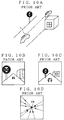
- Figs. 10A - 10C are views for explaining a change in a rear background image acquired by a video camera 1.
- Fig. 10A shows a status inclusive of one's own vehicle.
- Fig. 10B shows an image picked up by a video camera 1 at timing t in an environment of one's own vehicle.
- Fig. 10C shows an image picked up at timing t + ⁇ t.
- an edge point Pa of an object is detected from a luminance difference between the adjacent pixels on the image picked up by a camera.
- a point Pb of the image picked up by another camera corresponding to the detected edge point is detected.
- the position of an approaching vehicle is acquired by the pixel coordinates of Pa and Pb.
- the pertinent driver is given a warning of the existence of the vehicle approaching his own vehicle.
- a "correlative technique" of detecting the corresponding points between two frames of images has been adopted.
- a window W1 is set for a pixel Q at issue (Fig. 11A).
- the absolute value in the luminance difference between the corresponding pixels at timings t and t + ⁇ t is acquired. This operation will be carried out for each of the pixels constituting the image.
- the point in the window W2 when the sum of the luminance differences for the respective pixels is minimum is defined as a corresponding point, i.e. corresponding pixel R.
- the vector QR thus created is obtained as an optical flow (Fig. 11B).
- the correlative technique has the following disadvantage.
- the optical flow is detected on the basis of the luminance of each of the pixels constituting the window set within each of two frames of images picked up by a camera 1. Therefore, while a vehicle runs in bad weather such as fog or strong rain, the entire image picked-up will be whitish and hence the luminance of each of the corresponding pixels is approximately equal on the entire image. This makes it difficult to detect correct optical flows, and hence impossible to detect the approaching vehicle.
- the corresponding Pa and Pb between the two frames of images picked up by the two cameras are detected by means of the correlative technique. Therefore, while a vehicle runs in bad weather such as fog or strong rain, it is difficult to detect the corresponding points Pa and Pb, thereby making it impossible to detect another approaching vehicle.
- the environment monitoring system cannot detect the approaching vehicle, and cannot give a warning even if there is the approaching vehicle.
- a driver continues to run his own vehicle without knowing this fact, he may change the lane with the realization that there is no approaching vehicle. This may lead to the collision of his own vehicle with the approaching vehicle in the adjacent lane. In this way, it is very dangerous for a driver to run his own vehicle with no realization that the approaching vehicle cannot be detected.
- An object of the present invention is to provide an environment monitoring system which permits one's own vehicle to run safely even if an approaching vehicle cannot be detected.
- an environment monitoring system for a vehicle comprises:
- the decision means decides "NO" if prescribed information is not acquired at any timing from the image picked up by the image pick-up means. Therefore, it is possible to decide directly from the image picked up by the image pick-up means whether or not the approaching vehicle can be detected by the image processing means.
- the prescribed information is a first image of an object at a prescribed position in the image picked up by the pick-up means when the approaching vehicle can be detected by means of the image processing means;
- the decision means decides on the basis of similarity between the first image and the second image so that the image processing for only the second image to be performed for the decision can be reduced.
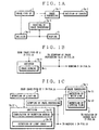
- the image processing means comprises: a white line detecting means 3a - 11 for detecting a white line from the image picked up at any timing by the image pickup means.
- the prescribed information is a normal detection degree of a white line to be acquired from the image picked up by the pick-up means when the approaching vehicle can be detected by means of the image processing means.
- the deciding means 3a - 3 comprises includes means 3a - 31 for computing an optional detection degree of the white line detected by the white line detecting means, and decides "NO" when the optional detecting degree does not satisfy the normal detection degree.
- the environment monitoring system further comprises a light-on detecting means 6 for detecting turn-on of a light of a vehicle running in the environment.
- the prescribed information includes the normal detection degree of the white line and a normal image from the light of another vehicle running in the environment in the image picked up by the pick-up means when the approaching vehicle can be detected by means of the image processing means.
- the deciding means comprises includes light image detecting means 3a -32 for detecting an optional image from the light of another vehicle running in the environment in the image picked up by the pick-up means at any timing; and when the light-on detecting means detects "ON" of the light, the deciding means decides "NO” if the optional image is an image not obtained when the approaching vehicle can be detected by means of the image processing means, and when the light-on detecting means does not detect "ON" of the light, it decides the normal detection degree of the white line as the prescribed information.
- the decision means 3a - 3 in the nighttime while the headlight is "ON”, the normal image obtained by the light is used as the prescribed information, and in the daytime while the headlight is "OFF", the degree of normal detection of the white line is used as the prescribed information. Therefore, in both daytime and nighttime, it can be detected by the decision means 3a - 3 whether or not the approaching vehicle can be detected by the image processing means 3a - 1.
- the deciding means decides "NO" when the wiper usage detecting means detects that the wiper is used. In this configuration, it can be decided indirectly without performing image processing whether or not the approaching vehicle can be detected.
- the image processing means includes an optical flow detecting means for detecting, as an optical flow, movement of the corresponding points in two images obtained at two timings by the image pick-up means; and the danger deciding means decides danger by detecting the vehicle approaching one's own vehicle on the basis of magnitude of the optical flow detected by the optical flow detecting means.
- the image processing means comprises:
- the white line detecting means for detecting the white line to detect the optical flow can be used to decide whether or not the approaching vehicle can be detected.
- the environment monitoring system comprises image processing stopping means for stopping the image processing means from detecting the approaching vehicle when the deciding means decides that the approaching vehicle cannot be detected by the image processing means.
- Fig. 2 is a block diagram of an embodiment of the environment monitoring system according to the present invention.
- a camera 1 loaded on a vehicle which serves as an image pick-up means, focuses an image over an angle of view defined by a lens 1a on an image plane 1b.
- the camera 1 is installed so that it can pick up a bumper 10 at a prescribed position in the image.
- a storage section 2 includes a first frame memory 2a, a second frame memory 2b, a differentiated frame memory 2c and a divergent optical flow memory 2d.
- the first and the second frame memory 2a and 2b temporarily store, as D2 and D3, the pixels in a m- by n- matrix (e.g. 512 x 512 pixels and with the luminance in 0 - 255 tones) converted from the image data D1 imaged on the image plane 1b of the camera 1, and supplies them to a microcomputer 3.
- n- matrix e.g. 512 x 512 pixels and with the luminance in 0 - 255 tones
- the first frame memory 2a and second frame memory 2b successively store the m x n pixel data D2 and D3 converted from the image picked up at an established period ⁇ t in such a manner that it is stored in the first frame memory 2a at timing t, in the second frame memory 2b at timing t + ⁇ t, ... ... .
- the differentiated image memory 2c stores the differentiated image data D4 created by differentiating the pixel data D2 and D3.
- the divergent optical flow memory 2d stores optical flow data D5 in a divergent direction and supplies them to the microcomputer 3.
- the microcomputer 3 is connected to a winker detection switch sensor 4.
- the winker detection switch which is attached to a winker mechanism of a vehicle, produces a winker signal S1 at "H" level when a winker (turn signal) switch turns on.
- the winker switch is turned on by a driver when he turns around the vehicle toward the right or left side.
- the microcomputer 3 includes a CPU 3a which operates in accordance with a control program, an ROM 3b for storing the control program for the CPU 3a and prescribed values, and RAM 3c for temporarily storing data necessary to perform computation of the CPU 3a.
- the ROM 3b which serves as an image storage means, stores first image data of the bumper 10, as shown in Fig. 4A, which should be picked up by the camera 1 when the approaching vehicle can be detected using optical flows.
- the CPU 3a which serves as a decision means, computes similarity between the second image data of the bumper 10 and the first image data stored in the ROM 3b at any optional timing when it is cut out from the pixel data D2 stored in the first frame memory 2a. If the similarity is lower than a prescribed value, the CPU 3a decides that the approaching vehicle cannot be detected using the optical flows, and supplies an audio signal S2 and image signal S3 to a warning generating section 5 which serves as a warning generating means. If the similarity is not lower than the prescribed value, the CPU 3a decides that the approaching vehicle can be detected using the optical flows. In this case, the CPU 3a operates as an optical flow detecting means to detect the optical flows and subsequently operates as a danger deciding means to decide the danger degree of collision with the approaching vehicle on the basis of the magnitude of the optical flows.
- the warning generating section 5 has a speaker 5a and display 5b.
- the speaker 5a indicates waning by a sound, i.e. generates audio guidance or warning on each of these facts.
- the display 5b displays the image picked up by the camera 1.
- the display 5b visually indicates the danger for the driver by displaying the pertinent message.
- the display 5a may be a display used for a television receiver.
- the pixel data D2 stored in the first frame memory 2a is captured.
- the pixel region corresponding to the bumper 10 is cut out from the captured data D2 to acquire the second image data.
- the luminance of the second image data is compared with that of the first image data of the bumper 10 when the approaching vehicle can be detected using the optical flows, as shown in Fig. 4A, thereby computing the similarity between the first image data and the second image data.
- the similarity is lower than the prescribed value (which occurs, for example when the luminance of the entire image is constant because fog has been generated as shown in Fig. 4B)
- the CPU 3a serves as an image processing stopping means so that it does not detect the optical flows. In this way, since the detection of the optical flows is not executed when the approaching vehicle cannot be detected, a driver is not misled by the incorrect detection of the approaching vehicle, thereby improving the safety of vehicle running.
- the speaker 5a is caused to make audio guidance that the approaching vehicle cannot be detected, and the display 5b is caused to display that "the approaching vehicle cannot be detected". If the similarity is higher than the prescribed value, the first image data can be acquired as the prescribed data from the image picked up by the camera 1. In this case, on the basis of the decision that the approaching vehicle can be detected using the optical flows, the optical flows are detected to detect and the approaching vehicle.
- the image processing for deciding whether or not the approaching vehicle can be detected can be reduced.
- the image data D1 picked up by the camera 1 is captured (step SP1).
- the captured data D1 is converted into the pixel data D2.
- the pixel region corresponding to the bumper 10 is cut out from the captured data D2 to acquire the second image data (step SP2).
- the luminance of the second image data is compared with that of the first image data of the bumper 10 when another approaching vehicle can be detected using the optical flows, thereby computing the similarity between the first image data and the second image data (step SP3).
- the similarity is lower than the prescribed value ("N" in step SP4), it is decided that the approaching vehicle cannot be detected using the optical flows.
- the warning for noticing this fact is generated from the speaker 5a and display 5b (step SP5).
- step SP4 If the similarity is higher than the prescribed value ("Y" in step SP4), it is decided that the approaching vehicle can be detected using the optical flows, and the image data D1 picked up at timing t is captured.
- the captured image data D1 is held in the first frame memory 2a (step SP6).
- the image data D1 picked up at timing t + ⁇ t is captured and held as pixel data D3 in the second frame memory 2b.
- the optical flows diverging from the FOE Fluors of Expansion
- step SP9 If the length of the optical flows stored in the divergent optical flow memory 2d is longer than a prescribed value, it is decided that there is the approaching vehicle ("Y" in step SP9). If a winker signal S1 has been produced from the winker detecting sensor ("Y” in step SP10), on the basis of the decision that lane changing is dangerous, the speaker 5a and display 5b are caused to generate a warning (step SP11). If the length of the optical flows is shorter than the prescribed length ("N" in step SP9), or it can be decided that the driver does not have no intention of changing his own lane because no winker signal S1 has been produced (“N” in step SP10), the processing is returned to step SP1.
- the bumper was used as a reference object, it may be any object such as a ball attached to the bumper as long as it can be located within a range where it can be picked up by the camera 1.
- the first image was used as the prescribed information.
- different items of prescribed information may be adopted according to whether or not a light-on signal S5 has been produced (Incidentally, the light-on signal S5 is produced from a light-on detecting sensor (light-on detecting means) 6 when a light-on switch for turning on/off a head light turns on).
- the prescribed information may be the normality detecting degree of the white line which is detected from the image picked up by the camera when the approaching vehicle can be detected.
- the prescribed information may be the normal image from the light of the other vehicle running in the environment, which is picked up by the camera 1 when the approaching vehicle can be detected.
- the normal detecting degree of the white line which can be detected over the entire image, it is not decided that the prescribed information has not been obtained even when the environment cannot be partially picked up by the camera 1 because of stain applied to the camera 1. Therefore, it can be detected whether or not the prescribed information has been acquired from the image picked up by the camera 1.
- the normal image from the light is used as the prescribed information
- the normal detection degree of the white line is used as the prescribed information. Therefore, in both daytime and nighttime, it can be detected whether or not the approaching vehicle can be detected.
- the camera supplies the image as shown in Fig. 6 as the image data D1.
- the image picked up by the camera includes a road 20, white lines 21 - 25 pained on the road 20, and side walls provided uprightly on both sides of the road which disappear at the center position in a horizontal line on an image screen.
- the image data D1 are stored as the pixel data D2 and D3 in the first frame memory 2a and the second frame memory 2b at prescribed intervals ⁇ t.
- a reference line V SL as shown in Fig. 8 is set for the differentiated image.
- the reference line V SL is set to run vertically on the differentiated image at a center position in the horizontal direction of the differentiated image. Namely, the reference line is set at a center in the horizontal direction of the lane on which one's own vehicle runs and sectioned by the white lines 22 and 23.
- searching is carried out of the edge points of a pair of white lines 22 and 23 which are located on both sides of one's own lane. Searching the edge points of the white lines 22 and 23 is carried out upward from a horizontal line H (LO) located at the bottom of the screen shown in Fig. 8. The edge points are searched from the lowermost end on the reference line V SL toward both ends in the horizontal direction. Thus, the edge points P (LO) of the white line 22 and P (RO) of the white line 23 are acquired which are located on the left and right side of the reference line V SL , respectively.
- the edge points are searched from the point P S1 , which is located at the second point from the lowermost end, toward both ends in the horizontal direction.
- the edge points P (L1) of the white line 22 and P (R1) of the white line 23 are acquired which are located on the left and right side of the reference line V SL , respectively.
- Such processing will be carried out successively upward to acquire the edge points on the differentiated image.
- the edge points P (L(m+2)) , P (R(m+2)) , P (L(m+2)) , P (Rm+2)) of the following vehicle will be taken so that only the edge points on the same line are further extracted.
- the CPU 3a can operate as the white line detecting means.
- the CPU 3a serves as a detection degree computing means. Namely, the CPU 3a counts what number of times (detection degree) the state where the number of edge points of the white line is smaller than a prescribed value continues. If the counted value exceeds a prescribed number of times, on the assumption that the normal detection degree as the prescribed information has not been satisfied, it is decided that the approaching vehicle cannot be detected, and warning is issued from the warning generating section.
- the pair of white lines 22 and 23 are detected which are located on both sides of one's own lane.
- the crossing point of the extended white lines 22 and 23 is set as FOE.
- the optical flows radially diverging from the FOE are detected to detect the approaching vehicle.
- the CPU 3a operates as a light image detecting means in the nighttime while the light-on signal S4 is produced. Namely, it extracts the pixels having the luminance larger than a prescribed value from pixel data D2 picked up by the camera 1 at any timing to detect any image from the light of another vehicle running in the environment of one's own vehicle. If the optional image thus detected is an image which is not acquired when the approaching vehicle can be detected (e.g. the detected image is larger because of rain than the normal image when the approaching image can be detected, or distorted because of fog), on the assumption that the approaching vehicle cannot be detected, warning is issued from the warning section 5.
- the image data D1 picked up at timing t as shown in Fig. 6 is captured from the camera 1. It is stored as the pixel data D2 in the first frame memory 2a (step SP102). The image data D1 picked up at timing t + ⁇ t is captured and stored as the pixel data D3 in the second frame memory 2b (step SP103).
- step SP104 These pixel data D2 and D3 are differentiated to extract the edge points so that the differentiated image as shown in Fig. 7 is created (step SP104).
- the white lines are detected (step SP105).
- N the light-on signal S4 has not been issued from the light-on detecting sensor 6
- step SP106 whether or not the number of edge points is smaller than a prescribed value is decided. If so ("Y" in step SP107), the count value of the counter in the RAM 3c is counted up (step SP108).
- step SP109 As a result of count-up, if the count value is larger than a prescribed number of times ("Y" in step SP109), on the assumption that the approaching vehicle cannot be detected using optical flows, the warning is indicated by means of the speaker 5a and display 5b. The processing is returned to step SP101.
- step SP111 If the number of the extracted edge points is larger that the prescribed value ("N" in step SP107), the counter is reset (step SP111).
- the crossing point of the extended lines of the detected white lines is set as the FOE (step SP112).
- the optical flows are detected (step SP113). Then the optical flows are oriented in a direction diverging from the FOE, and have a length exceeding a prescribed length, it is decided that another vehicle is approaching one's own vehicle ("Y" in step SP114).
- the state of the winker detecting sensor 4 is captured (step SP115). If the winker signal S1 has been produced ("Y" in step SP115), the warning is indicated by means of the speaker 5a and display 5b (step 116). Thereafter, the processing is returned to step SP101.
- step SP114 If there is no approaching vehicle (i.e. the optical flows are in a direction of converging into the FOE or a length not exceeding the prescribed length in the diverging direction) ("N" in step SP114), or the winker signal S1 has not been issued (the driver has no intention of lane changing), on the assumption that the danger degree is low, the processing is returned to step SP101.
- step SP101 If the head light signal S4 has been produced ("Y" in step SP101), on the assumption that it is in the nighttime, the image data D1 is captured from the camera 1 (step SP117), and converted into the pixel data D2.
- the pixels having the luminance exceeding the prescribed value in the pixel data D2 are detected as an optional image from the light of the vehicle running in the environment (step SP118). If the optional image is an image which is not obtained when the approaching vehicle can be detected ("Y" in step SP119), the processing proceeds to step SP110. If the optional image is the normal image obtained when the approaching vehicle can be detected ("Y" in step SP119), the processing proceeds to step SP102.
- the approaching vehicle can be detected using the optical flows, thereby reducing the production cost of the system.
- the number of times the state where the number of edge points of the white line is smaller than a prescribed value continues is counted as the optional detection degree.
- the total number of edges of the white line when it is detected at a prescribed number of times may be detected as the optional detection degree. In this case, if the total number of edges is smaller than a prescribed value, it is decided that the approaching vehicle can be detected. Further, the number of times the state where the white line cannot be detected continues may be counted as the optional detection degree. In this case , if the count value is larger than the prescribed value, it is decided that the approaching vehicle cannot be detected.
- the prescribed information By deciding whether or not the prescribed information can be acquired as in the first and the second embodiment, it can be decided directly from the image picked up by the camera whether or not the approaching vehicle can be detected. Thus, it can be properly decided that the approaching vehicle cannot be detected.
- the approaching vehicle is detected using the optical flows, thereby deciding the danger degree.
- the position P of the approaching vehicle is computed using two cameras, the danger degree can be decided on the computed position. In this case, even if the one of them can detect another approaching vehicle, if the other camera thereof cannot detect it because of stain, the approaching vehicle cannot be resultantly detected. Therefore, it must be decided whether or not the prescribed information can be acquired from the images picked up by two cameras, respectively.
- a wiper signal may be used in order to decide that the optical flows cannot be detected.
- a wiper sensor is connected to the microcomputer 3.
- the wiper sensor is served as a wiper usage detecting means which produces a wiper signal S5 at H level when a wiper switch is turned on.
- the wiper signal is produced from the wiper sensor.
- the production cost for the monitoring system can be reduced.
Landscapes
- Physics & Mathematics (AREA)
- General Physics & Mathematics (AREA)
- Engineering & Computer Science (AREA)
- Human Computer Interaction (AREA)
- Mechanical Engineering (AREA)
- Traffic Control Systems (AREA)
- Emergency Alarm Devices (AREA)
- Image Analysis (AREA)
- Image Processing (AREA)
Abstract
Description
Claims (9)
- An environment monitoring system for a vehicle comprising:image-pickup means loaded on the vehicle for picking up an environment of the vehicle to acquire an image;image-processing means for processing the image to detect an approaching vehicle;danger deciding means for danger for said approaching vehicle;means for deciding whether or not the approaching vehicle can be detected by means of said image processing means with a help of prescribed information when the approaching vehicle can be detected; andwarning means for giving warning when it is decided that said approaching vehicle cannot be detected by means of said image processing means.
- An environment monitoring means according to claim 1, wherein said decision means decides "NO" if prescribed information is not acquired at any timing from the image picked up by said image pick-up means.
- An environment monitoring means according to claim 2, wherein said prescribed information is a first image of an object at a prescribed position in the image picked up by said pick-up means when the approaching vehicle can be detected by means of said image processing means; andsaid deciding means has an image storing means for storing said first image, said deciding means decides "NO" if similarity between said first image stored in said image storing means and a second image of the object at the prescribed position in the image picked up at any timing by said image pick-up means is lower than a prescribed value.
- An environment monitoring means according to claim 2, wherein said image processing means further comprises: a white line detecting means for detecting a white line from the image picked up at any timing by said image pick-up means,said prescribed information is a normal detection degree of a white line to be acquired from the image picked up by said pick-up means when the approaching vehicle can be detected by means of said image processing means; andsaid deciding means comprises includes means for computing an optional detection degree of the white line detected by said white line detecting means, and decides "NO" when said optional detecting degree does not satisfy the normal detection degree.
- An environment monitoring system according to claim 4, further comprising a light-on detecting means for detecting turn-on of a light of the vehicle running in the environment, wherein said prescribed information includes said normal detection degree of the white line and a normal image from the light of the vehicle running in the environment in the image picked up by said pick-up means when the approaching vehicle can be detected by means of said image processing means;said deciding means comprises includes light image detecting means for detecting an optional image from the light of the vehicle running in the environment in the image picked up by said pick-up means at any timing; and when the light-on detecting means detects "ON" of the light, said decides "NO" if the optional image is an image not obtained when the approaching vehicle can be detected by means of said image processing means, and when the light-on detecting means does not detect "ON" of the light, it decides the normal detection degree of the white line as said prescribed information.
- An environment monitoring system according to claim 1, wherein said deciding means includes a wiper usage detecting means whether or not a wiper is used, and decides "NO" when the wiper usage detecting means detects that the wiper is used.
- An environment monitoring system according to claim 2, wherein said image processing means includes an optical flow detecting means for detecting, as an optical flow, movement of the corresponding points in two images obtained at two timings by said image pick-up means; andsaid danger deciding means decides danger by detecting the vehicle approaching one's own vehicle on the basis of magnitude of the optical flow detected by said optical flow detecting means.
- An environment monitoring system according to claim 4, wherein said image processing means comprises:said white line detecting means for detecting a pair of white lines located on both sides of one's own lane on which one's own vehicle should run;optical flow detecting means for setting a crossing point of extended lines of said pair of white lines as an FOE (focus of expansion) and detecting, as an optical flow, movement of the corresponding points in two images obtained at two timings by said image pick-up means; andsaid danger deciding means decides danger by detecting the vehicle approaching one's own vehicle on the basis of magnitude of the optical flow detected by said optical flow detecting means.
- An environment monitoring system according to claim 1, further comprising image processing stopping means for stopping said image processing means from detecting the approaching vehicle when said decides that the approaching vehicle cannot be detected by said image processing means.
Applications Claiming Priority (2)
| Application Number | Priority Date | Filing Date | Title |
|---|---|---|---|
| JP05243499A JP3990836B2 (en) | 1999-03-01 | 1999-03-01 | Vehicle periphery monitoring device |
| JP5243499 | 1999-03-01 |
Publications (3)
| Publication Number | Publication Date |
|---|---|
| EP1033285A2 true EP1033285A2 (en) | 2000-09-06 |
| EP1033285A3 EP1033285A3 (en) | 2004-12-01 |
| EP1033285B1 EP1033285B1 (en) | 2008-06-11 |
Family
ID=12914656
Family Applications (1)
| Application Number | Title | Priority Date | Filing Date |
|---|---|---|---|
| EP00104077A Expired - Lifetime EP1033285B1 (en) | 1999-03-01 | 2000-02-28 | Environment monitoring system |
Country Status (4)
| Country | Link |
|---|---|
| US (1) | US6549124B1 (en) |
| EP (1) | EP1033285B1 (en) |
| JP (1) | JP3990836B2 (en) |
| DE (1) | DE60039139D1 (en) |
Cited By (4)
| Publication number | Priority date | Publication date | Assignee | Title |
|---|---|---|---|---|
| WO2004039069A1 (en) * | 2002-10-24 | 2004-05-06 | Daimlerchrysler Ag | Method and device for operating a night vision system for cars |
| FR2867567A1 (en) * | 2004-03-09 | 2005-09-16 | Denso Corp | Vehicle traveling state detection system, has electronic control unit to determine state of vehicle based on signal from speed sensor and optical flux of predetermined point of image captured during travel of vehicle |
| WO2011139211A1 (en) * | 2010-05-05 | 2011-11-10 | Autoliv Development Ab | A driver assisting system and method for a motor vehicle |
| EP2487907A4 (en) * | 2009-10-09 | 2016-05-11 | Panasonic Ip Man Co Ltd | DEVICE FOR MONITORING A VEHICLE ENVIRONMENT |
Families Citing this family (13)
| Publication number | Priority date | Publication date | Assignee | Title |
|---|---|---|---|---|
| US7852462B2 (en) * | 2000-05-08 | 2010-12-14 | Automotive Technologies International, Inc. | Vehicular component control methods based on blind spot monitoring |
| JP4953498B2 (en) * | 2000-07-12 | 2012-06-13 | 富士重工業株式会社 | Outside vehicle monitoring device with fail-safe function |
| JP3966170B2 (en) * | 2002-12-05 | 2007-08-29 | 株式会社デンソー | Driving assistance device |
| JP4176558B2 (en) * | 2003-06-06 | 2008-11-05 | 本田技研工業株式会社 | Vehicle periphery display device |
| JP2005170323A (en) * | 2003-12-15 | 2005-06-30 | Denso Corp | Runway shape display device |
| JP4818816B2 (en) * | 2006-06-05 | 2011-11-16 | 富士通株式会社 | Parking assistance program and parking assistance device |
| JP4991384B2 (en) * | 2007-05-08 | 2012-08-01 | 株式会社日立製作所 | Approaching object detection device and approaching object detection program |
| JP5716343B2 (en) * | 2010-10-01 | 2015-05-13 | トヨタ自動車株式会社 | Vehicle object recognition system |
| JP5659913B2 (en) * | 2011-03-30 | 2015-01-28 | 富士通株式会社 | Alarm device, alarm system, and alarm method |
| US9598076B1 (en) | 2015-10-22 | 2017-03-21 | Ford Global Technologies, Llc | Detection of lane-splitting motorcycles |
| DE112018007036B4 (en) * | 2018-03-12 | 2022-12-08 | Mitsubishi Electric Corporation | FOG DETERMINATION DEVICE, FOG DETERMINATION PROCEDURE AND FOG DETERMINATION PROGRAM |
| JP2019217970A (en) * | 2018-06-21 | 2019-12-26 | 日本電産コパル株式会社 | Electronic mirror device and image display method |
| CN109492609B (en) * | 2018-11-27 | 2020-05-15 | 上海芯仑光电科技有限公司 | Method and vehicle for detecting lane lines, and computing device |
Family Cites Families (18)
| Publication number | Priority date | Publication date | Assignee | Title |
|---|---|---|---|---|
| US4641136A (en) * | 1985-04-18 | 1987-02-03 | Thaddeus Kowalczyk | Security eyes for prevention of car accidents |
| US5463384A (en) * | 1991-02-11 | 1995-10-31 | Auto-Sense, Ltd. | Collision avoidance system for vehicles |
| JP3452268B2 (en) * | 1993-08-06 | 2003-09-29 | 矢崎総業株式会社 | Rear side monitoring method for vehicles |
| JP3263699B2 (en) * | 1992-12-22 | 2002-03-04 | 三菱電機株式会社 | Driving environment monitoring device |
| JPH06276430A (en) * | 1993-03-24 | 1994-09-30 | Isuzu Motors Ltd | Lane departure warning device |
| JPH06308256A (en) * | 1993-04-26 | 1994-11-04 | Hitachi Cable Ltd | Cloudy fog detecting method |
| JP3352157B2 (en) * | 1993-07-06 | 2002-12-03 | マツダ株式会社 | Car safety equipment |
| US6553130B1 (en) * | 1993-08-11 | 2003-04-22 | Jerome H. Lemelson | Motor vehicle warning and control system and method |
| GB2286307A (en) * | 1994-02-02 | 1995-08-09 | Eric Collier | Distance alarm device |
| JP3287117B2 (en) * | 1994-07-05 | 2002-05-27 | 株式会社日立製作所 | Environment recognition device for vehicles using imaging device |
| GB2291244B (en) * | 1994-07-15 | 1998-02-11 | Design Technology & Innovation | Vehicle safety systems |
| JPH08285534A (en) * | 1995-04-12 | 1996-11-01 | Suzuki Motor Corp | In-vehicle image processing device |
| JPH0939601A (en) * | 1995-08-04 | 1997-02-10 | Mitsubishi Motors Corp | Drowsy driving alarm |
| JPH09113221A (en) * | 1995-10-17 | 1997-05-02 | Mitsubishi Electric Corp | Vehicle-mounted image processing apparatus and image processing method thereof |
| JPH09142207A (en) * | 1995-11-17 | 1997-06-03 | Yazaki Corp | Vehicle periphery monitoring device |
| JP3644149B2 (en) * | 1996-09-10 | 2005-04-27 | 日産自動車株式会社 | Inter-vehicle distance control type constant speed travel device |
| JPH11249212A (en) * | 1998-03-02 | 1999-09-17 | Olympus Optical Co Ltd | Camera with blurring warning function |
| JPH11353565A (en) * | 1998-06-09 | 1999-12-24 | Yazaki Corp | Vehicle collision warning method and device |
-
1999
- 1999-03-01 JP JP05243499A patent/JP3990836B2/en not_active Expired - Fee Related
-
2000
- 2000-02-28 DE DE60039139T patent/DE60039139D1/en not_active Expired - Lifetime
- 2000-02-28 US US09/514,354 patent/US6549124B1/en not_active Expired - Lifetime
- 2000-02-28 EP EP00104077A patent/EP1033285B1/en not_active Expired - Lifetime
Cited By (4)
| Publication number | Priority date | Publication date | Assignee | Title |
|---|---|---|---|---|
| WO2004039069A1 (en) * | 2002-10-24 | 2004-05-06 | Daimlerchrysler Ag | Method and device for operating a night vision system for cars |
| FR2867567A1 (en) * | 2004-03-09 | 2005-09-16 | Denso Corp | Vehicle traveling state detection system, has electronic control unit to determine state of vehicle based on signal from speed sensor and optical flux of predetermined point of image captured during travel of vehicle |
| EP2487907A4 (en) * | 2009-10-09 | 2016-05-11 | Panasonic Ip Man Co Ltd | DEVICE FOR MONITORING A VEHICLE ENVIRONMENT |
| WO2011139211A1 (en) * | 2010-05-05 | 2011-11-10 | Autoliv Development Ab | A driver assisting system and method for a motor vehicle |
Also Published As
| Publication number | Publication date |
|---|---|
| US6549124B1 (en) | 2003-04-15 |
| DE60039139D1 (en) | 2008-07-24 |
| EP1033285A3 (en) | 2004-12-01 |
| JP2000251198A (en) | 2000-09-14 |
| JP3990836B2 (en) | 2007-10-17 |
| EP1033285B1 (en) | 2008-06-11 |
Similar Documents
| Publication | Publication Date | Title |
|---|---|---|
| EP1033285B1 (en) | Environment monitoring system | |
| US10992908B2 (en) | Vehicular vision system with dual processor control | |
| US10915761B2 (en) | Vehicular vision system with determination of a bicycle approaching from rearward of the vehicle | |
| US10449899B2 (en) | Vehicle vision system with road line sensing algorithm and lane departure warning | |
| US8386114B2 (en) | Imaging system for vehicle | |
| US6259359B1 (en) | Rear monitoring system for vehicle | |
| US7379815B2 (en) | Lane detection apparatus | |
| US8477191B2 (en) | On-vehicle image pickup apparatus | |
| JP4707109B2 (en) | Multi-camera image processing method and apparatus | |
| EP1035455A1 (en) | Rear monitoring system | |
| JP5213063B2 (en) | Vehicle display device and display method | |
| JP2007228448A (en) | Imaging environment recognition device | |
| EP2830926A1 (en) | Vehicular imaging system and method for determining roadway width | |
| JP4951481B2 (en) | Road marking recognition device | |
| US20160180158A1 (en) | Vehicle vision system with pedestrian detection | |
| US12420707B2 (en) | Vehicular control system with cross traffic alert and collision avoidance | |
| CN115088248A (en) | Image pickup apparatus, image pickup system, and image pickup method | |
| JP3464368B2 (en) | Rear side monitoring device for vehicles | |
| JP2014106740A (en) | In-vehicle parking frame recognizing device | |
| JP2003151096A (en) | Approach warning device | |
| CN118264872A (en) | Camera setting device and method, camera device, vehicle and storage medium | |
| US20230222813A1 (en) | Road surface marking detection device, notification system provided with the same, and road surface marking detection | |
| JP4476957B2 (en) | Attitude discrimination device |
Legal Events
| Date | Code | Title | Description |
|---|---|---|---|
| PUAI | Public reference made under article 153(3) epc to a published international application that has entered the european phase |
Free format text: ORIGINAL CODE: 0009012 |
|
| AK | Designated contracting states |
Kind code of ref document: A2 Designated state(s): AT BE CH CY DE DK ES FI FR GB GR IE IT LI LU MC NL PT SE |
|
| AX | Request for extension of the european patent |
Free format text: AL;LT;LV;MK;RO;SI |
|
| PUAL | Search report despatched |
Free format text: ORIGINAL CODE: 0009013 |
|
| AK | Designated contracting states |
Kind code of ref document: A3 Designated state(s): AT BE CH CY DE DK ES FI FR GB GR IE IT LI LU MC NL PT SE |
|
| AX | Request for extension of the european patent |
Extension state: AL LT LV MK RO SI |
|
| 17P | Request for examination filed |
Effective date: 20050425 |
|
| AKX | Designation fees paid |
Designated state(s): DE FR IT |
|
| RAP1 | Party data changed (applicant data changed or rights of an application transferred) |
Owner name: YAZAKI CORPORATION Owner name: KABUSHIKI KAISHA TOSHIBA |
|
| RIN1 | Information on inventor provided before grant (corrected) |
Inventor name: OKAMOTO, KEIKI Inventor name: ISHIKAWA, NAOTO Inventor name: TANIGUCHI, YASUHIROC Inventor name: FUJINAMI, KAZUTOMO |
|
| RAP1 | Party data changed (applicant data changed or rights of an application transferred) |
Owner name: YAZAKI CORPORATION Owner name: KABUSHIKI KAISHA TOSHIBA |
|
| GRAP | Despatch of communication of intention to grant a patent |
Free format text: ORIGINAL CODE: EPIDOSNIGR1 |
|
| GRAS | Grant fee paid |
Free format text: ORIGINAL CODE: EPIDOSNIGR3 |
|
| GRAA | (expected) grant |
Free format text: ORIGINAL CODE: 0009210 |
|
| AK | Designated contracting states |
Kind code of ref document: B1 Designated state(s): DE FR IT |
|
| REF | Corresponds to: |
Ref document number: 60039139 Country of ref document: DE Date of ref document: 20080724 Kind code of ref document: P |
|
| PLBE | No opposition filed within time limit |
Free format text: ORIGINAL CODE: 0009261 |
|
| STAA | Information on the status of an ep patent application or granted ep patent |
Free format text: STATUS: NO OPPOSITION FILED WITHIN TIME LIMIT |
|
| 26N | No opposition filed |
Effective date: 20090312 |
|
| REG | Reference to a national code |
Ref country code: FR Ref legal event code: PLFP Year of fee payment: 17 |
|
| PGFP | Annual fee paid to national office [announced via postgrant information from national office to epo] |
Ref country code: DE Payment date: 20160225 Year of fee payment: 17 Ref country code: IT Payment date: 20160226 Year of fee payment: 17 |
|
| PGFP | Annual fee paid to national office [announced via postgrant information from national office to epo] |
Ref country code: FR Payment date: 20160224 Year of fee payment: 17 |
|
| REG | Reference to a national code |
Ref country code: DE Ref legal event code: R119 Ref document number: 60039139 Country of ref document: DE |
|
| REG | Reference to a national code |
Ref country code: FR Ref legal event code: ST Effective date: 20171031 |
|
| PG25 | Lapsed in a contracting state [announced via postgrant information from national office to epo] |
Ref country code: DE Free format text: LAPSE BECAUSE OF NON-PAYMENT OF DUE FEES Effective date: 20170901 Ref country code: FR Free format text: LAPSE BECAUSE OF NON-PAYMENT OF DUE FEES Effective date: 20170228 |
|
| PG25 | Lapsed in a contracting state [announced via postgrant information from national office to epo] |
Ref country code: IT Free format text: LAPSE BECAUSE OF NON-PAYMENT OF DUE FEES Effective date: 20170228 |