EP1033224A1 - Verfahren zur Fertigung von Kunststofformteilen mit thermisch höher belasteten Segmenten - Google Patents
Verfahren zur Fertigung von Kunststofformteilen mit thermisch höher belasteten Segmenten Download PDFInfo
- Publication number
- EP1033224A1 EP1033224A1 EP00103367A EP00103367A EP1033224A1 EP 1033224 A1 EP1033224 A1 EP 1033224A1 EP 00103367 A EP00103367 A EP 00103367A EP 00103367 A EP00103367 A EP 00103367A EP 1033224 A1 EP1033224 A1 EP 1033224A1
- Authority
- EP
- European Patent Office
- Prior art keywords
- component
- temperature
- polyamide
- materials
- components
- Prior art date
- Legal status (The legal status is an assumption and is not a legal conclusion. Google has not performed a legal analysis and makes no representation as to the accuracy of the status listed.)
- Withdrawn
Links
- 238000004519 manufacturing process Methods 0.000 title claims abstract description 17
- 239000002991 molded plastic Substances 0.000 title 1
- 239000000463 material Substances 0.000 claims abstract description 121
- 239000000203 mixture Substances 0.000 claims abstract description 16
- 239000003365 glass fiber Substances 0.000 claims abstract description 10
- 239000011159 matrix material Substances 0.000 claims abstract description 10
- XLYOFNOQVPJJNP-UHFFFAOYSA-N water Substances O XLYOFNOQVPJJNP-UHFFFAOYSA-N 0.000 claims abstract description 8
- 239000000654 additive Substances 0.000 claims abstract description 4
- 230000006641 stabilisation Effects 0.000 claims abstract description 3
- 238000011105 stabilization Methods 0.000 claims abstract description 3
- 238000002347 injection Methods 0.000 claims description 41
- 239000007924 injection Substances 0.000 claims description 41
- 238000000034 method Methods 0.000 claims description 41
- 238000001746 injection moulding Methods 0.000 claims description 28
- 239000004952 Polyamide Substances 0.000 claims description 23
- 229920002647 polyamide Polymers 0.000 claims description 23
- 229920003023 plastic Polymers 0.000 claims description 17
- 239000004033 plastic Substances 0.000 claims description 17
- 229920001169 thermoplastic Polymers 0.000 claims description 15
- 229920001577 copolymer Polymers 0.000 claims description 13
- 239000004416 thermosoftening plastic Substances 0.000 claims description 13
- 229920000642 polymer Polymers 0.000 claims description 10
- 239000004697 Polyetherimide Substances 0.000 claims description 9
- 239000004734 Polyphenylene sulfide Substances 0.000 claims description 9
- 229910052500 inorganic mineral Inorganic materials 0.000 claims description 9
- 239000011707 mineral Substances 0.000 claims description 9
- 229920002492 poly(sulfone) Polymers 0.000 claims description 9
- 229920001601 polyetherimide Polymers 0.000 claims description 9
- 229920000069 polyphenylene sulfide Polymers 0.000 claims description 9
- 239000004954 Polyphthalamide Substances 0.000 claims description 7
- 229920006375 polyphtalamide Polymers 0.000 claims description 7
- 239000004695 Polyether sulfone Substances 0.000 claims description 6
- PPBRXRYQALVLMV-UHFFFAOYSA-N Styrene Chemical compound C=CC1=CC=CC=C1 PPBRXRYQALVLMV-UHFFFAOYSA-N 0.000 claims description 6
- 125000003118 aryl group Chemical group 0.000 claims description 6
- 239000011162 core material Substances 0.000 claims description 6
- 229920006393 polyether sulfone Polymers 0.000 claims description 6
- 229920000571 Nylon 11 Polymers 0.000 claims description 5
- 229920000299 Nylon 12 Polymers 0.000 claims description 5
- 229920002292 Nylon 6 Polymers 0.000 claims description 4
- 239000010410 layer Substances 0.000 claims description 4
- 239000012792 core layer Substances 0.000 claims description 3
- 239000000178 monomer Substances 0.000 claims description 3
- 230000008646 thermal stress Effects 0.000 claims description 3
- 239000012764 mineral filler Substances 0.000 abstract 1
- 239000000306 component Substances 0.000 description 112
- 238000010438 heat treatment Methods 0.000 description 4
- 239000000155 melt Substances 0.000 description 4
- 239000000243 solution Substances 0.000 description 4
- 239000000945 filler Substances 0.000 description 3
- 239000008187 granular material Substances 0.000 description 3
- 238000003780 insertion Methods 0.000 description 3
- 230000037431 insertion Effects 0.000 description 3
- 230000035882 stress Effects 0.000 description 3
- 230000007704 transition Effects 0.000 description 3
- 229920012266 Poly(ether sulfone) PES Polymers 0.000 description 2
- 238000002485 combustion reaction Methods 0.000 description 2
- 239000008358 core component Substances 0.000 description 2
- 239000011241 protective layer Substances 0.000 description 2
- 238000003466 welding Methods 0.000 description 2
- 229930182556 Polyacetal Natural products 0.000 description 1
- 229920002877 acrylic styrene acrylonitrile Polymers 0.000 description 1
- 239000012080 ambient air Substances 0.000 description 1
- 230000009286 beneficial effect Effects 0.000 description 1
- 239000003086 colorant Substances 0.000 description 1
- 239000002131 composite material Substances 0.000 description 1
- 150000001875 compounds Chemical class 0.000 description 1
- 230000004927 fusion Effects 0.000 description 1
- 229920000578 graft copolymer Polymers 0.000 description 1
- 238000010137 moulding (plastic) Methods 0.000 description 1
- 239000004417 polycarbonate Substances 0.000 description 1
- 229920000515 polycarbonate Polymers 0.000 description 1
- 229920000728 polyester Polymers 0.000 description 1
- 229920000098 polyolefin Polymers 0.000 description 1
- 229920006324 polyoxymethylene Polymers 0.000 description 1
- 239000012858 resilient material Substances 0.000 description 1
- 239000007787 solid Substances 0.000 description 1
- 229920000638 styrene acrylonitrile Polymers 0.000 description 1
- 239000011145 styrene acrylonitrile resin Substances 0.000 description 1
- 239000013077 target material Substances 0.000 description 1
Images

Classifications
-
- B—PERFORMING OPERATIONS; TRANSPORTING
- B29—WORKING OF PLASTICS; WORKING OF SUBSTANCES IN A PLASTIC STATE IN GENERAL
- B29C—SHAPING OR JOINING OF PLASTICS; SHAPING OF MATERIAL IN A PLASTIC STATE, NOT OTHERWISE PROVIDED FOR; AFTER-TREATMENT OF THE SHAPED PRODUCTS, e.g. REPAIRING
- B29C45/00—Injection moulding, i.e. forcing the required volume of moulding material through a nozzle into a closed mould; Apparatus therefor
- B29C45/16—Making multilayered or multicoloured articles
-
- B—PERFORMING OPERATIONS; TRANSPORTING
- B29—WORKING OF PLASTICS; WORKING OF SUBSTANCES IN A PLASTIC STATE IN GENERAL
- B29C—SHAPING OR JOINING OF PLASTICS; SHAPING OF MATERIAL IN A PLASTIC STATE, NOT OTHERWISE PROVIDED FOR; AFTER-TREATMENT OF THE SHAPED PRODUCTS, e.g. REPAIRING
- B29C65/00—Joining or sealing of preformed parts, e.g. welding of plastics materials; Apparatus therefor
- B29C65/02—Joining or sealing of preformed parts, e.g. welding of plastics materials; Apparatus therefor by heating, with or without pressure
-
- B—PERFORMING OPERATIONS; TRANSPORTING
- B29—WORKING OF PLASTICS; WORKING OF SUBSTANCES IN A PLASTIC STATE IN GENERAL
- B29K—INDEXING SCHEME ASSOCIATED WITH SUBCLASSES B29B, B29C OR B29D, RELATING TO MOULDING MATERIALS OR TO MATERIALS FOR MOULDS, REINFORCEMENTS, FILLERS OR PREFORMED PARTS, e.g. INSERTS
- B29K2081/00—Use of polymers having sulfur, with or without nitrogen, oxygen or carbon only, in the main chain, as moulding material
- B29K2081/04—Polysulfides, e.g. PPS, i.e. polyphenylene sulfide or derivatives thereof
Definitions
- the present invention relates to a method of manufacturing from Plastic molded parts with higher thermal stressed segments, for example engine attachments such as suction systems.
- Plastic moldings which consist of several components, can in Injection molding processes are manufactured, hereinafter referred to as Multi-component injection molding process. Will the components one after the other, possibly with a simultaneous phase, through a joint Injection point injected, molded parts are formed that are skin and at least have a core layer. This process is called sandwich injection molding or also referred to as a coinjection method.
- Each component has at least one injection point injected, the components are partially positioned side by side.
- To this process includes bio-injection molding, in which the injected melt flows meet directly. You can simultaneously or injected at different times.
- overmolding or also Compound injection molding known processes are separated from Cavity parts using cores, slides or rotating devices.
- the partial cooled preform, consisting of the first component, is partially with one or more components overmolded.
- the thermal conditions are advantageous in the biinjection process Clash of the melts, causing for a very large number of Materials a connection can be realized. Very beneficial and of the much lower ones are also of great economic interest Tool costs because of complex and costly cores and turning functions can be omitted.
- the cycle time is usually still considerably shorter than with comparable parts with successive injection phases.
- DE 42 24 171 A1 discloses an injection molded part as well as a method and a Injection mold for the production of injection molded parts.
- the parts point at least two colors and / or at least two different plastics on and are in at least two successive process steps, in which the plastics are successively injected into an injection mold are produced.
- DE 42 24 171 A1 remains after the process step the injection of the first plastic into the injection molded part closed tool; then one adjoining the injection molded part Cavity created or released and in this the second plastic injected.
- the injection mold has at least one Slide on the cavity provided for the injection molded part in the mold changed.
- DE-U-93 19 190.1 relates to a molded part with a resistant surface.
- the Molded part consists of a supporting lower part from a first thermoplastic polymer and a surrounding protective layer of one second thermoplastic polymer based on polyamide 11 or polyamide 12, the protective layer has a thickness of between 0.2 due to the shape and process and 5 mm and can have targeted functional breakthroughs.
- the first Polymer can be selected from the group consisting of polyamide, polyester, polyolefin, polyacetal, Polycarbonate, polyphthalamide and their blends can be formed
- the second polymer from the group of homo- or copolymers of polyamide 11, Polyamide 12, their blends with each other or their blends with the semicrystalline or amorphous homo- or copolyamides can be formed.
- the molded part manufactured using the coinjection process, has one more resistant surface compared to the core material, the Material properties of the high hardness only on the edge zone of the component is provided.
- this object is achieved in that a cavity at least two materials can be fed, the materials A and at least one further material A different from A, which is a component 1 and one of 1 contains various temperature-resistant component 2.
- Another The solution according to the invention consists of a material A containing Component component and at least one further component component, the one Material B with a component 1 and a temperature-resistant Component 2 contains to be welded together.
- the material B a contains temperature-resistant component 2 and component 1.
- a finally mentioned further solution according to the invention provides for one Injection molding process with at least two materials, one component from one Inject material B, which is a temperature-resistant component 2 and Component 1 contains and with at least one further material A, um- or to inject.
- the advantages associated with the solutions according to the invention are diverse nature.
- the methods according to the invention can be used thermally Manufacturing highly stressed component parts from materials that are of higher quality, with the less stressed parts from cheaper Polymers can be produced.
- By adding the Component 1 to component 2 of material B becomes this material B made more or less similar to material A. It turned out that the fusion areas on the components have no weak points represent and are both thermally and mechanically highly stressable. This makes it possible to achieve a design that meets the demands in which the higher quality materials in the thermally stressed parts of the component can be provided while in the less stressed component parts the cheaper polymer is located.
- Material A and material B can contain additives that serve, for example, to stabilize the two materials. Both Materials A and B can contain up to 60% glass fibers, minerals or one Glass fiber / mineral mixture up to 60% included. In further configurations, material A contains as component 1 one or more polyamides from the group of polyamides 6, 6.6., 4.6, 11 or 12, PPA (polyphthalamide) or other copolymers based on Polyamide. Component 1 of material A can also be a copolyamide contain aromatic or non-aromatic monomer units.
- material A can be used as further component 2 a thermoplastic from the group of polyethersulfone (PES), Polysulfone (PSU), polyetherimide (PEI), polyphenylene sulfide (PPS), copolymers based on these polymers or a styrene-containing copolymer.
- PES polyethersulfone
- PSU Polysulfone
- PEI polyetherimide
- PPS polyphenylene sulfide
- copolymers based on these polymers or a styrene-containing copolymer copolymers based on these polymers or a styrene-containing copolymer.
- the material B contains, in addition to the optional ones listed above Fillers on the one hand as component 1, preferably polyamide 6, polyamide 6.6 or the polyamide 4.6 or the polyamide 11 or the polyamide 12 or PPA or other copolymers.
- material B preferably contains thermoplastics as component 2 from the group of polyethersulfone (PES), polysulfone (PSU), Polyetherimide (PEI) or polyphenylene sulfide (PPS) or copolymers based of these polymers or a copolymer containing styrene.
- PES polyethersulfone
- PSU polysulfone
- PEI Polyetherimide
- PPS polyphenylene sulfide
- the proportions are based on the thermoplastic matrix for component 2 preferably between 50% and 99% and for component 1 between 1% and 50%, d. H. in addition to the temperature-resistant component 2, material B must always contain a component 1.
- temperature-resistant materials can be used Connect plastic components together by welding.
- One of the too welding component parts contains material A, while the component component to be connected therewith comprises a component B, with a temperature-resistant component 2 and optionally components Component 1.
- the Material A forms the skin layer and material B the core layer.
- the core component can target material A, for example at the end of the flow path break through, so that no more in thermally stressed areas of the molded part Layer structure, but only the pure core material B is present. It is also conceivable the production of components with a layer structure, in which the Material A is used in the core and material B as the skin.
- the Melt When producing the molded parts using the biinjection process, the Melt injected so that the materials in the component partially next to each other lie.
- the thermally resilient material becomes thermally higher positioned area.
- the materials can both can be injected simultaneously and sequentially.
- the components can also be made by manufacturing a preform Material A or B can be produced if this is then with the second material is partially overmolded, overmolded or injection molded.
- These components can with a multi-component injection molding machine, which with a Multi-component injection mold is manufactured. Also with one-component machines and tools, as described, such molded parts are manufactured in the insertion process.
- components with thermal Produce more highly stressed component parts economically the thermally higher stressed component parts from which the temperature-resistant component 2 containing material B exist and the less stressed Component components can consist of material A.
- components that are manufactured according to the method according to the invention can be the suction system, the intake manifold, cylinder head cover, water tank, Injection pump and the water pump as engine components from Internal combustion engines called.
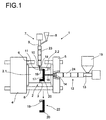
- the Injection molding machine 1 shows schematically an injection molding machine 1 reproduced, which is a vertical injection unit 7 for material B and a has horizontal injection unit 12 for material A.
- the Injection molding machine 1 contains a tool 2 with a cavity; the tool 2 is divided into two halves 2.1 and 2.2 in the parting plane 3.
- the Tool half 2.2 is received on a fixed plate 5, the Tool half 2.1 sits on a movable plate 4, which on guide rails 6th is movable to demold the component 17.
- the vertical injection unit 7, via which a blend of components 1 and Material B containing component 2 is supplied comprises a Granulator 8, an injection molding cylinder 9, which from heating tapes 23rd is surrounded and opens with a nozzle 10 in a sprue 11.
- vertical injection unit 7 can contain a material B. Melt flow are injected into the cavity 2 and there forms the thermal higher stressed component parts 18 on the plastic component 17.
- the horizontal injection unit 12 the material A Cavity 2 supplied, which passes through a nozzle 14 into the sprue 16 and in the cavity the less stressed component parts 20 am Forms plastic component 17.
- Material A can, for example, have a Granule hopper 15 are fed to the injection unit 12, the cylinder 13 can also be heated via heating tapes 24.
- the material A is fed via the horizontal injection unit 12.
- This material A contains, for example as component 1, a polyamide, for example polyamide 6, 6.6, 4.6, 11 or 12 or PPA.
- a copolyamide with aromatic or non-aromatic monomer units can also be used as component 1 in material A which can be supplied via the second injection unit.
- the material A may in addition to component 1 made of a polymer such as polyamides exemplified as component 2, materials such as PES, PSU, PEI, PPS, SAN or ASA (that is, in the latter two cases S tyrol- A cryl n itril copolymers or A crylnitril- S tyrol- A crylester-graft copolymers) containing; material A can also have additives for stabilization. Up to a proportion of 60% glass fibers or minerals or up to the same proportion glass fiber / mineral mixtures can be used as fillers for material A.
- the proportion of component 1 within the thermoplastic matrix of material A can be between 50% and 100%, the temperature-resistant component 2 being able to assume a proportion between 0% and 50%. A proportion of 100% means the presence of a pure polymer without admixtures, based on the thermoplastic matrix.
- the material B a blend
- the material B can be made by means of the vertical injection unit 7 containing the components 1 and the temperature-resistant component 2, in insert the cavity 2 of the tool.
- This material B can range from 0% to Contain 60% glass fibers, minerals or mixtures thereof as filler, while the remaining portion of material B is formed from a blend becomes.
- the blend is made from component 1 and the temperature-resistant Component 2 formed, the proportion of component 1 preferably between 1% and 50% and the proportion of the temperature-resistant component 2 based on the thermoplastic matrix between 50% and 99%.
- the Material B which can be regarded as the higher quality material for example as component 2 polyethersulfone, polysulfone, polyetherimide or Contain polyphenylene sulfide.
- component 1 in the blend are preferably from the Materials listed above, in particular made of polyamides.
- the Material B can be analogous to material A instead of a glass fiber or Mineral content between 0% and 60%, one in the same range Contain part of a glass fiber / mineral mixture; the thermoplastic matrix of material B becomes more temperature-resistant due to the blend Component 2 such as PES, PSU, PEI or PPS and component 1 are formed.
- the components 17 to be manufactured, the locally higher temperatures endure, can be injection molded in a conventional manner, for example, according to known multi-component injection molding processes such as that Composite injection molding, sandwich injection molding with or without targeted Breakthrough of the core component or after the insertion process.
- FIG. 2 shows a component manufactured according to the method according to the invention with parts with higher thermal loads and zones with fewer Stress shown.
- FIG. 2 the side view of a suction pipe 25 is shown, with 26 the engine-side flange of the intake manifold 25 is designated.
- several individual intake pipes 27 extend between the engine side Flange 26 and a collector 31 of the plastic component 25, in the present Trap a suction pipe.
- the injection point for lies in the center of the collector 31 the material B, the melt flow for the more thermally stressable Component 28.
- There the melt flow occurs thermally higher loadable component 28 in the cavity and spreads in this corresponding to the flow fronts 33 shown in FIG.
- intake manifold is with the invention Process also economically producing others locally thermally high claimed engine attachments possible, in particular Cylinder head covers, gear housings, water boxes, injection and Water pumps would be mentioned.
Landscapes
- Engineering & Computer Science (AREA)
- Manufacturing & Machinery (AREA)
- Mechanical Engineering (AREA)
- Injection Moulding Of Plastics Or The Like (AREA)
Abstract
Description
- Figur 1
- eine Spritzgießmaschine mit einem vertikalen Spritzaggregat für Werkstoff B und ein horizontales Spritzaggregat für Werkstoff A und
- Figur 2
- ein gemäß der erfindungsgemäßen Verfahren gefertigtes Kunststoffbauteil mit thermisch höher belastbaren Bauteilpartien, den Werkstoff B mit temperaturbeständiger Komponente 2 und Partien mit geringer Beanspruchung, den Werkstoff A enthaltend.
- 1
- Spritzgießmaschine
- 2
- Werkzeug
- 2.1
- erste Werkzeughälfte
- 2.2
- zweite Werkzeughälfte
- 3
- Trennebene
- 4
- bewegliche Platte
- 5
- feste Platte
- 6
- Führungsholme
- 7
- vertikales Spritzaggregat
- 8
- Granulattrichter
- 9
- Spritzgießzylinder
- 10
- Düse
- 11
- Angußkanal
- 12
- horizontales Spritzaggregat
- 13
- Zylinder
- 14
- Düse
- 15
- Granulattrichter
- 16
- Angußkanal
- 17
- Kunststoffbauteil
- 18
- thermisch beanspruchte Bauteilpartie
- 19
- Werkstoff B
- 20
- thermisch geringer beanspruchte Bauteilpartie
- 21
- Werkstoff A
- 22
- entformtes Bauteil
- 23
- Heizbänder
- 24
- Heizbänder
- 25
- Saugrohr
- 26
- Flansch
- 27
- Einzelsaugrohr
- 28
- Einspritzpunkte des thermisch höher beanspruchbaren Werkstoffes B
- 29
- Einspritzpunkte des geringer beanspruchbaren Werkstoffes A
- 30
- Übergangsbereich
- 31
- Sammler
- 32
- Fließfront Werkstoff A (zu verschiedenen Zeitpunkten)
- 33
- Fließfront Werkstoff B (zu verschiedenen Zeitpunkten)
Claims (17)
- Verfahren zur Fertigung von temperaturbeständigen Kunststoffbauteilen, nach einem Spritzgießverfahren, wobei einer Kavität (2) mindestens zwei Werkstoffe zuführbar sind, dadurch gekennzeichnet, daß der Kavität (2) ein Werkstoff A und mindestens ein weiterer von A verschiedener Werkstoff B zugeführt werden, wobei der Werkstoff B eine Komponente 1 und eine von 1 verschiedene temperaturbeständige Komponente 2 enthält.
- Verfahren gemäß Anspruch 1, dadurch gekennzeichnet, daß die Werkstoffe A und/oder B Additive zum Stabilisieren enthalten.
- Verfahren gemäß Anspruch 1, dadurch gekennzeichnet, daß die Werkstoffe A und/oder B bis zu 60% Glasfasern enthalten.
- Verfahren gemäß Anspruch 1, dadurch gekennzeichnet, daß die Werkstoffe A und/oder B bis zu 60% Mineralien enthalten.
- Verfahren gemäß Anspruch 1, dadurch gekennzeichnet, daß die Werkstoffe A und/oder B bis zu 60% eines Glasfaser/Mineralgemisches enthalten.
- Verfahren gemäß Anspruch 1, dadurch gekennzeichnet, daß der Werkstoff A eines oder mehrere Polyamide aus der Gruppe von Polyamid 6, Polyamid 6.6, Polyamid 4.6, Polyamid 11, Polyamid 12, Polyphthalamid oder anderen Copolymeren auf Basis von Polyamid als Komponente 1 enthält.
- Verfahren gemäß Anspruch 6, dadurch gekennzeichnet, daß der Werkstoff A ein Copolyamid mit aromatischen oder nicht aromatischen Monomerbausteinen als Komponente 1 enthält.
- Verfahren gemäß Anspruch 1, dadurch gekennzeichnet, daß der Werkstoff A einen zusätzlichen Thermoplast aus der Gruppe Polyethersulfon, Polysulfon, Polyetherimid, Polyphenylensulfid, Copolymere auf Basis dieser Polymere oder ein Styrol enthaltendes Copolymer als temperaturbeständige Komponente 2 enthält.
- Verfahren gemäß Anspruch 1, dadurch gekennzeichnet, daß der Werkstoff B eines oder mehrere Polyamide aus der Gruppe Polyamid 6, Polyamid 6.6, Polyamid 4.6, Polyamid 11, Polyamid 12 oder Copolymere als Komponente 1 einerseits und ein Thermoplast aus der Gruppe Polyethersulfon, Polysulfon, Polyetherimid, Polyphenylensulfid oder deren Copolymere als temperaturbeständige Komponente 2 andererseits enthält.
- Verfahren gemäß einem oder mehrerer der vorhergehenden Ansprüche, dadurch gekennzeichnet, daß im Werkstoff A die Anteile der Komponenten 1 und 2 bezogen auf die thermoplastische Matrix für Komponente 1 zwischen 50% und 100% und für Komponente 2 zwischen 0% und 50% liegen.
- Verfahren gemäß einem oder mehrerer der vorhergehenden Ansprüche, dadurch gekennzeichnet, daß im Werkstoff B die Anteile der Komponenten 1 und 2 bezogen auf die thermoplastische Matrix für Komponente 2 zwischen 50% und 99% und für Komponente 1 zwischen 1% und 50% liegen.
- Verfahren zur Fertigung von temperaturbeständigen Kunststoffbauteilen, wobei eine Bauteilkomponente einen Werkstoff A enthält und mindestens eine weitere Bauteilkomponente einen Werkstoff B mit einer Komponente 1 und einer temperaturbeständigen Komponente 2 enthält und die Bauteilkomponenten miteinander verschweißt werden.
- Verfahren zur Fertigung von temperaturbeständigen Kunststoffbauteilen nach einem Spritzgießverfahren, mit mindestens zwei Werkstoffen, dadurch gekennzeichnet, daß ein Bauteil aus einem Werkstoff A gespritzt und mit mindestens einem weiteren Werkstoff B über-, um- oder angespritzt wird, der eine temperaturbeständige Komponente 2 und eine Komponente 1 enthält.
- Verfahren zur Fertigung von temperaturbeständigen Kunststoffbauteilen nach einem Spritzgießverfahren mit mindestens zwei Werkstoffen, dadurch gekennzeichnet, daß ein Bauteil aus einem einen Werkstoff B, der eine temperaturbeständige Komponente 2 und eine Komponente 1 enthält, gespritzt wird und mit mindestens einem weiteren Werkstoff A über-, um-oder angespritzt wird.
- Verfahren gemäß des Anspruchs 13 oder 14, dadurch gekennzeichnet, daß die beiden Werkstoffe A und B entweder zeitlich nacheinander oder auch simultan eingespritzt werden.
- Verfahren zur Fertigung von temperaturbeständigen Kunststoffbauteilen nach einem Spritzgießverfahren mit mindestens zwei Werkstoffen, dadurch gekennzeichnet, daß der Werkstoff A die Hautschicht und der Werkstoff B die Kernschicht bildet und umgekehrt, wobei der Kernwerkstoff lokal - je nach thermischer Beanspruchung des Bauteils - den Hautwerkstoff durchbricht.
- Bauteile wie Ansauganlage, Saugrohr, Zylinderkopfhaube, Getriebegehäuse, Wasserbehälter, Einspritz- oder Wasserpumpe mit thermisch höher beanspruchten Zonen, gefertigt gemäß der Verfahren nach einem oder mehrerer der vorhergehenden Ansprüche, dadurch gekennzeichnet, daß die thermisch höher belasteten Bauteilpartien (18) aus einem Werkstoff B mit einer temperaturbeständigen Komponente 2 und einer Komponente 1 bestehen und die geringer beanspruchten Bauteilpartien (20) aus einem Werkstoff A bestehen.
Applications Claiming Priority (2)
| Application Number | Priority Date | Filing Date | Title |
|---|---|---|---|
| DE1999108846 DE19908846A1 (de) | 1999-03-01 | 1999-03-01 | Verfahren zur Fertigung von Kunststofformteilen mit thermisch höher belasteten Segmenten |
| DE19908846 | 1999-03-01 |
Publications (1)
| Publication Number | Publication Date |
|---|---|
| EP1033224A1 true EP1033224A1 (de) | 2000-09-06 |
Family
ID=7899280
Family Applications (1)
| Application Number | Title | Priority Date | Filing Date |
|---|---|---|---|
| EP00103367A Withdrawn EP1033224A1 (de) | 1999-03-01 | 2000-02-22 | Verfahren zur Fertigung von Kunststofformteilen mit thermisch höher belasteten Segmenten |
Country Status (2)
| Country | Link |
|---|---|
| EP (1) | EP1033224A1 (de) |
| DE (1) | DE19908846A1 (de) |
Cited By (4)
| Publication number | Priority date | Publication date | Assignee | Title |
|---|---|---|---|---|
| EP1362692A1 (de) * | 2002-05-17 | 2003-11-19 | Magneti Marelli Powertrain Spa | Zweischichtiges Rohr mit Innenschicht aus polymeren Material mit einer HDT-A von mindestens 275 C |
| CN102926901A (zh) * | 2011-08-09 | 2013-02-13 | 劳士领汽车配件(苏州)有限公司 | 一种1.4tsi进气歧管下盖的工艺改进 |
| DE102013220800B3 (de) * | 2013-10-15 | 2015-04-02 | Robert Bosch Gmbh | Getrieberad sowie Verfahren und Werkzeug zum Herstellen eines Getrieberads |
| FR3054183A1 (fr) * | 2016-07-22 | 2018-01-26 | Treves Products, Services & Innovation | Capot de protection acoustique pour moteur de vehicule automobile |
Families Citing this family (4)
| Publication number | Priority date | Publication date | Assignee | Title |
|---|---|---|---|---|
| US6640783B2 (en) * | 2001-02-15 | 2003-11-04 | Delphi Technologies, Inc. | Composite fuel rail with integral damping and a co-injected non-permeation layer |
| DE102005034081A1 (de) * | 2005-07-21 | 2007-01-25 | Uvex Arbeitsschutz Gmbh | Verfahren zur Herstellung eines Brillenbügels |
| DE102010002549B3 (de) | 2010-03-03 | 2011-07-07 | Faurecia Kunststoffe Automobilsysteme GmbH, 85057 | Spritzgussverfahren |
| DE102020207781A1 (de) | 2020-06-23 | 2021-12-23 | Volkswagen Aktiengesellschaft | Rotor für eine elektrische Maschine |
Citations (8)
| Publication number | Priority date | Publication date | Assignee | Title |
|---|---|---|---|---|
| EP0489437A2 (de) * | 1990-12-05 | 1992-06-10 | Mitsui Petrochemical Industries, Ltd. | Aromatische Polyamidharzzusammensetzung |
| JPH06218766A (ja) * | 1993-01-27 | 1994-08-09 | Kunimori Kagaku:Kk | 多色成形方法 |
| EP0658422A1 (de) * | 1993-12-14 | 1995-06-21 | Ems-Inventa Ag | Formteil mit resistenter Oberfläche |
| EP0722990A2 (de) * | 1994-12-26 | 1996-07-24 | Shin-Etsu Chemical Co., Ltd. | Thermoplastische Harzzusammensetzungen für integrales Formverfahren mit Siliconkautschuk und integrale Formkörper |
| US5679424A (en) * | 1993-08-06 | 1997-10-21 | Hoechst Aktiengesellschaft | Injection molding of thermoplastic material including from 2 to 8% by weight of glass fibers |
| EP0904919A2 (de) * | 1997-09-26 | 1999-03-31 | Basf Aktiengesellschaft | Verfahren zur Herstellung von Verbundformteilen aus thermoplastischen Kunststoffen |
| JPH11268574A (ja) * | 1998-03-23 | 1999-10-05 | Trinity Ind Corp | 灰皿蓋及び灰皿 |
| DE19820420A1 (de) * | 1998-05-07 | 1999-11-18 | Ejot Kunststofftech Gmbh | Gehäuse für einen Scheinwerfer |
-
1999
- 1999-03-01 DE DE1999108846 patent/DE19908846A1/de not_active Withdrawn
-
2000
- 2000-02-22 EP EP00103367A patent/EP1033224A1/de not_active Withdrawn
Patent Citations (8)
| Publication number | Priority date | Publication date | Assignee | Title |
|---|---|---|---|---|
| EP0489437A2 (de) * | 1990-12-05 | 1992-06-10 | Mitsui Petrochemical Industries, Ltd. | Aromatische Polyamidharzzusammensetzung |
| JPH06218766A (ja) * | 1993-01-27 | 1994-08-09 | Kunimori Kagaku:Kk | 多色成形方法 |
| US5679424A (en) * | 1993-08-06 | 1997-10-21 | Hoechst Aktiengesellschaft | Injection molding of thermoplastic material including from 2 to 8% by weight of glass fibers |
| EP0658422A1 (de) * | 1993-12-14 | 1995-06-21 | Ems-Inventa Ag | Formteil mit resistenter Oberfläche |
| EP0722990A2 (de) * | 1994-12-26 | 1996-07-24 | Shin-Etsu Chemical Co., Ltd. | Thermoplastische Harzzusammensetzungen für integrales Formverfahren mit Siliconkautschuk und integrale Formkörper |
| EP0904919A2 (de) * | 1997-09-26 | 1999-03-31 | Basf Aktiengesellschaft | Verfahren zur Herstellung von Verbundformteilen aus thermoplastischen Kunststoffen |
| JPH11268574A (ja) * | 1998-03-23 | 1999-10-05 | Trinity Ind Corp | 灰皿蓋及び灰皿 |
| DE19820420A1 (de) * | 1998-05-07 | 1999-11-18 | Ejot Kunststofftech Gmbh | Gehäuse für einen Scheinwerfer |
Non-Patent Citations (4)
| Title |
|---|
| DATABASE WPI Week 199953, Derwent World Patents Index; AN 1999-615141, XP002139816 * |
| HAGEN R: "VERBUNDSPRITZGIESSEN VON POLYAMIDWERKSTOFFEN - NEUE KONSTRUKTIONSMOGLICHKEITEN FUR BRILLENGESTELLE", KUNSTSTOFFE,DE,CARL HANSER VERLAG. MUNCHEN, vol. 79, no. 1, 1 January 1989 (1989-01-01), pages 72 - 76, XP000071878, ISSN: 0023-5563 * |
| PATENT ABSTRACTS OF JAPAN vol. 018, no. 585 (M - 1700) 9 November 1994 (1994-11-09) * |
| PATENT ABSTRACTS OF JAPAN vol. 2000, no. 01 31 January 2000 (2000-01-31) * |
Cited By (4)
| Publication number | Priority date | Publication date | Assignee | Title |
|---|---|---|---|---|
| EP1362692A1 (de) * | 2002-05-17 | 2003-11-19 | Magneti Marelli Powertrain Spa | Zweischichtiges Rohr mit Innenschicht aus polymeren Material mit einer HDT-A von mindestens 275 C |
| CN102926901A (zh) * | 2011-08-09 | 2013-02-13 | 劳士领汽车配件(苏州)有限公司 | 一种1.4tsi进气歧管下盖的工艺改进 |
| DE102013220800B3 (de) * | 2013-10-15 | 2015-04-02 | Robert Bosch Gmbh | Getrieberad sowie Verfahren und Werkzeug zum Herstellen eines Getrieberads |
| FR3054183A1 (fr) * | 2016-07-22 | 2018-01-26 | Treves Products, Services & Innovation | Capot de protection acoustique pour moteur de vehicule automobile |
Also Published As
| Publication number | Publication date |
|---|---|
| DE19908846A1 (de) | 2000-09-07 |
Similar Documents
| Publication | Publication Date | Title |
|---|---|---|
| DE69421803T2 (de) | Verfahren zum herstellen von nadeln | |
| DE3850704T2 (de) | Spritzgiessen dreischichtiger Hohlkörper. | |
| DE102011012900A1 (de) | Faserverstärktes Kunststoffverbundbauteil und dessen Herstellung | |
| WO1998023431A1 (de) | Verfahren und vorrichtung zur herstellung eines mehrschicht-kunststoffteils | |
| DE102010019625A1 (de) | Verfahren zur Herstellung einer Verbund- oder Hybridkonstruktion | |
| DE102009046164A1 (de) | Verfahren zur Herstellung eines Mehrkomponenten-Wischerarms | |
| DE10106458A1 (de) | Verfahren zur Herstellung von Verbundteilen durch Mehrkomponentenspritzguss | |
| EP2860010B1 (de) | Vorrichtung und Verfahren zur Herstellung eines mehrschichtigen hohlen Formteils aus faserverstärktem Kunststoff | |
| DE10227636A1 (de) | Verfahren und Vorrichtung zum Herstellen mehrkomponentiger Kunststoff-Formteile | |
| WO2001098052A1 (de) | Verfahren zur herstellung eines hybridteils | |
| KR0180045B1 (ko) | 합성수지 성형체의 제조방법 | |
| EP1033224A1 (de) | Verfahren zur Fertigung von Kunststofformteilen mit thermisch höher belasteten Segmenten | |
| DE102014011135B4 (de) | Verfahren und Vorrichtung zur Herstellung eines Dekorteils | |
| DE2513594A1 (de) | Formwerkzeug zur herstellung von formteilen aus einem ein treibmittel enthaltenden thermoplastischen kunststoff | |
| EP2552663A1 (de) | Verfahren zur herstellung eines endlosfaserverstärkten formteils unter verwendung eines spritzgusswerkzeugs | |
| DE4224171A1 (de) | Spritzgußteil sowie Verfahren und Spritzgießwerkzeug zum Herstellen von Spritzgußteilen | |
| DE19736063C2 (de) | Chipkarte | |
| EP4045263B1 (de) | Spritzgusswerkzeug und verfahren zu dessen herstellung sowie verfahren zur herstellung von marmorierten formteilen | |
| DE102011014538B3 (de) | Faserverbundkunststoffbauteil mit thermoplastischer Matrix und dessen Herstellungsverfahren | |
| DE19504332A1 (de) | Verfahren zur gleichzeitigen Herstellung und Montage von Einzelteilen im Spritzguß | |
| EP4049821B1 (de) | Verbundbauteil und verfahren zur herstellung eines verbundbauteils | |
| DE102018215660A1 (de) | Spritzgießwerkzeug zur Herstellung von Spritzgussbauteilen, sowie Verfahren zur Herstellung von Spritzgussbauteilen | |
| DE102014224720A1 (de) | Verfahren zur Herstellung eines schnittbearbeiteten Formteils mit einer Kunststoffmatrix und Verstärkungsfasern | |
| EP1046486B1 (de) | Formwerkzeug zur Herstellung von mehreren montagegespritzten Bauteilen | |
| DE102023106152A1 (de) | Verfahren zur Herstellung eines Formteils mittels einer Kunststoffspritzgießmaschine, Volumensplitter zur Durchführung des Verfahrens, Spritzgießwerkzeug zur Durchführung des Verfahrens und Formteil |
Legal Events
| Date | Code | Title | Description |
|---|---|---|---|
| PUAI | Public reference made under article 153(3) epc to a published international application that has entered the european phase |
Free format text: ORIGINAL CODE: 0009012 |
|
| AK | Designated contracting states |
Kind code of ref document: A1 Designated state(s): BE DE ES FR GB IT |
|
| AX | Request for extension of the european patent |
Free format text: AL;LT;LV;MK;RO;SI |
|
| 17P | Request for examination filed |
Effective date: 20010305 |
|
| AKX | Designation fees paid |
Free format text: BE DE ES FR GB IT |
|
| 17Q | First examination report despatched |
Effective date: 20010917 |
|
| GRAH | Despatch of communication of intention to grant a patent |
Free format text: ORIGINAL CODE: EPIDOS IGRA |
|
| RIN1 | Information on inventor provided before grant (corrected) |
Inventor name: BLUHM, RUEDIGER, DR. Inventor name: ENDEMANN, ULRICH, DR. Inventor name: WILHELM, WOLFGANG Inventor name: HOMES, ANGELIKA Inventor name: EICHENAUER, ULRICH, DR. |
|
| STAA | Information on the status of an ep patent application or granted ep patent |
Free format text: STATUS: THE APPLICATION IS DEEMED TO BE WITHDRAWN |
|
| 18D | Application deemed to be withdrawn |
Effective date: 20030902 |