EP1033217A2 - Rotor for a mixer and mixer having the same - Google Patents
Rotor for a mixer and mixer having the same Download PDFInfo
- Publication number
- EP1033217A2 EP1033217A2 EP00102763A EP00102763A EP1033217A2 EP 1033217 A2 EP1033217 A2 EP 1033217A2 EP 00102763 A EP00102763 A EP 00102763A EP 00102763 A EP00102763 A EP 00102763A EP 1033217 A2 EP1033217 A2 EP 1033217A2
- Authority
- EP
- European Patent Office
- Prior art keywords
- blade
- rotor
- blades
- start point
- mixing
- Prior art date
- Legal status (The legal status is an assumption and is not a legal conclusion. Google has not performed a legal analysis and makes no representation as to the accuracy of the status listed.)
- Withdrawn
Links
Images




Classifications
-
- B—PERFORMING OPERATIONS; TRANSPORTING
- B29—WORKING OF PLASTICS; WORKING OF SUBSTANCES IN A PLASTIC STATE IN GENERAL
- B29B—PREPARATION OR PRETREATMENT OF THE MATERIAL TO BE SHAPED; MAKING GRANULES OR PREFORMS; RECOVERY OF PLASTICS OR OTHER CONSTITUENTS OF WASTE MATERIAL CONTAINING PLASTICS
- B29B7/00—Mixing; Kneading
- B29B7/02—Mixing; Kneading non-continuous, with mechanical mixing or kneading devices, i.e. batch type
- B29B7/06—Mixing; Kneading non-continuous, with mechanical mixing or kneading devices, i.e. batch type with movable mixing or kneading devices
- B29B7/10—Mixing; Kneading non-continuous, with mechanical mixing or kneading devices, i.e. batch type with movable mixing or kneading devices rotary
- B29B7/18—Mixing; Kneading non-continuous, with mechanical mixing or kneading devices, i.e. batch type with movable mixing or kneading devices rotary with more than one shaft
- B29B7/183—Mixing; Kneading non-continuous, with mechanical mixing or kneading devices, i.e. batch type with movable mixing or kneading devices rotary with more than one shaft having a casing closely surrounding the rotors, e.g. of Banbury type
- B29B7/186—Rotors therefor
-
- B—PERFORMING OPERATIONS; TRANSPORTING
- B29—WORKING OF PLASTICS; WORKING OF SUBSTANCES IN A PLASTIC STATE IN GENERAL
- B29B—PREPARATION OR PRETREATMENT OF THE MATERIAL TO BE SHAPED; MAKING GRANULES OR PREFORMS; RECOVERY OF PLASTICS OR OTHER CONSTITUENTS OF WASTE MATERIAL CONTAINING PLASTICS
- B29B7/00—Mixing; Kneading
- B29B7/02—Mixing; Kneading non-continuous, with mechanical mixing or kneading devices, i.e. batch type
- B29B7/06—Mixing; Kneading non-continuous, with mechanical mixing or kneading devices, i.e. batch type with movable mixing or kneading devices
- B29B7/10—Mixing; Kneading non-continuous, with mechanical mixing or kneading devices, i.e. batch type with movable mixing or kneading devices rotary
- B29B7/18—Mixing; Kneading non-continuous, with mechanical mixing or kneading devices, i.e. batch type with movable mixing or kneading devices rotary with more than one shaft
-
- B—PERFORMING OPERATIONS; TRANSPORTING
- B29—WORKING OF PLASTICS; WORKING OF SUBSTANCES IN A PLASTIC STATE IN GENERAL
- B29B—PREPARATION OR PRETREATMENT OF THE MATERIAL TO BE SHAPED; MAKING GRANULES OR PREFORMS; RECOVERY OF PLASTICS OR OTHER CONSTITUENTS OF WASTE MATERIAL CONTAINING PLASTICS
- B29B7/00—Mixing; Kneading
- B29B7/02—Mixing; Kneading non-continuous, with mechanical mixing or kneading devices, i.e. batch type
- B29B7/06—Mixing; Kneading non-continuous, with mechanical mixing or kneading devices, i.e. batch type with movable mixing or kneading devices
- B29B7/10—Mixing; Kneading non-continuous, with mechanical mixing or kneading devices, i.e. batch type with movable mixing or kneading devices rotary
- B29B7/18—Mixing; Kneading non-continuous, with mechanical mixing or kneading devices, i.e. batch type with movable mixing or kneading devices rotary with more than one shaft
- B29B7/183—Mixing; Kneading non-continuous, with mechanical mixing or kneading devices, i.e. batch type with movable mixing or kneading devices rotary with more than one shaft having a casing closely surrounding the rotors, e.g. of Banbury type
-
- B—PERFORMING OPERATIONS; TRANSPORTING
- B29—WORKING OF PLASTICS; WORKING OF SUBSTANCES IN A PLASTIC STATE IN GENERAL
- B29B—PREPARATION OR PRETREATMENT OF THE MATERIAL TO BE SHAPED; MAKING GRANULES OR PREFORMS; RECOVERY OF PLASTICS OR OTHER CONSTITUENTS OF WASTE MATERIAL CONTAINING PLASTICS
- B29B7/00—Mixing; Kneading
- B29B7/30—Mixing; Kneading continuous, with mechanical mixing or kneading devices
- B29B7/34—Mixing; Kneading continuous, with mechanical mixing or kneading devices with movable mixing or kneading devices
- B29B7/38—Mixing; Kneading continuous, with mechanical mixing or kneading devices with movable mixing or kneading devices rotary
- B29B7/46—Mixing; Kneading continuous, with mechanical mixing or kneading devices with movable mixing or kneading devices rotary with more than one shaft
- B29B7/465—Mixing; Kneading continuous, with mechanical mixing or kneading devices with movable mixing or kneading devices rotary with more than one shaft each shaft comprising rotor parts of the Banbury type in addition to screw parts
-
- B—PERFORMING OPERATIONS; TRANSPORTING
- B29—WORKING OF PLASTICS; WORKING OF SUBSTANCES IN A PLASTIC STATE IN GENERAL
- B29B—PREPARATION OR PRETREATMENT OF THE MATERIAL TO BE SHAPED; MAKING GRANULES OR PREFORMS; RECOVERY OF PLASTICS OR OTHER CONSTITUENTS OF WASTE MATERIAL CONTAINING PLASTICS
- B29B7/00—Mixing; Kneading
- B29B7/30—Mixing; Kneading continuous, with mechanical mixing or kneading devices
- B29B7/34—Mixing; Kneading continuous, with mechanical mixing or kneading devices with movable mixing or kneading devices
- B29B7/38—Mixing; Kneading continuous, with mechanical mixing or kneading devices with movable mixing or kneading devices rotary
- B29B7/46—Mixing; Kneading continuous, with mechanical mixing or kneading devices with movable mixing or kneading devices rotary with more than one shaft
- B29B7/48—Mixing; Kneading continuous, with mechanical mixing or kneading devices with movable mixing or kneading devices rotary with more than one shaft with intermeshing devices, e.g. screws
- B29B7/482—Mixing; Kneading continuous, with mechanical mixing or kneading devices with movable mixing or kneading devices rotary with more than one shaft with intermeshing devices, e.g. screws provided with screw parts in addition to other mixing parts, e.g. paddles, gears, discs
-
- B—PERFORMING OPERATIONS; TRANSPORTING
- B29—WORKING OF PLASTICS; WORKING OF SUBSTANCES IN A PLASTIC STATE IN GENERAL
- B29B—PREPARATION OR PRETREATMENT OF THE MATERIAL TO BE SHAPED; MAKING GRANULES OR PREFORMS; RECOVERY OF PLASTICS OR OTHER CONSTITUENTS OF WASTE MATERIAL CONTAINING PLASTICS
- B29B7/00—Mixing; Kneading
- B29B7/30—Mixing; Kneading continuous, with mechanical mixing or kneading devices
- B29B7/34—Mixing; Kneading continuous, with mechanical mixing or kneading devices with movable mixing or kneading devices
- B29B7/38—Mixing; Kneading continuous, with mechanical mixing or kneading devices with movable mixing or kneading devices rotary
- B29B7/46—Mixing; Kneading continuous, with mechanical mixing or kneading devices with movable mixing or kneading devices rotary with more than one shaft
- B29B7/48—Mixing; Kneading continuous, with mechanical mixing or kneading devices with movable mixing or kneading devices rotary with more than one shaft with intermeshing devices, e.g. screws
- B29B7/488—Parts, e.g. casings, sealings; Accessories, e.g. flow controlling or throttling devices
-
- B—PERFORMING OPERATIONS; TRANSPORTING
- B29—WORKING OF PLASTICS; WORKING OF SUBSTANCES IN A PLASTIC STATE IN GENERAL
- B29B—PREPARATION OR PRETREATMENT OF THE MATERIAL TO BE SHAPED; MAKING GRANULES OR PREFORMS; RECOVERY OF PLASTICS OR OTHER CONSTITUENTS OF WASTE MATERIAL CONTAINING PLASTICS
- B29B7/00—Mixing; Kneading
- B29B7/30—Mixing; Kneading continuous, with mechanical mixing or kneading devices
- B29B7/34—Mixing; Kneading continuous, with mechanical mixing or kneading devices with movable mixing or kneading devices
- B29B7/38—Mixing; Kneading continuous, with mechanical mixing or kneading devices with movable mixing or kneading devices rotary
- B29B7/46—Mixing; Kneading continuous, with mechanical mixing or kneading devices with movable mixing or kneading devices rotary with more than one shaft
- B29B7/48—Mixing; Kneading continuous, with mechanical mixing or kneading devices with movable mixing or kneading devices rotary with more than one shaft with intermeshing devices, e.g. screws
- B29B7/488—Parts, e.g. casings, sealings; Accessories, e.g. flow controlling or throttling devices
- B29B7/489—Screws
-
- B—PERFORMING OPERATIONS; TRANSPORTING
- B29—WORKING OF PLASTICS; WORKING OF SUBSTANCES IN A PLASTIC STATE IN GENERAL
- B29B—PREPARATION OR PRETREATMENT OF THE MATERIAL TO BE SHAPED; MAKING GRANULES OR PREFORMS; RECOVERY OF PLASTICS OR OTHER CONSTITUENTS OF WASTE MATERIAL CONTAINING PLASTICS
- B29B7/00—Mixing; Kneading
- B29B7/74—Mixing; Kneading using other mixers or combinations of mixers, e.g. of dissimilar mixers ; Plant
- B29B7/7476—Systems, i.e. flow charts or diagrams; Plants
- B29B7/7495—Systems, i.e. flow charts or diagrams; Plants for mixing rubber
-
- B—PERFORMING OPERATIONS; TRANSPORTING
- B29—WORKING OF PLASTICS; WORKING OF SUBSTANCES IN A PLASTIC STATE IN GENERAL
- B29C—SHAPING OR JOINING OF PLASTICS; SHAPING OF MATERIAL IN A PLASTIC STATE, NOT OTHERWISE PROVIDED FOR; AFTER-TREATMENT OF THE SHAPED PRODUCTS, e.g. REPAIRING
- B29C48/00—Extrusion moulding, i.e. expressing the moulding material through a die or nozzle which imparts the desired form; Apparatus therefor
- B29C48/25—Component parts, details or accessories; Auxiliary operations
- B29C48/36—Means for plasticising or homogenising the moulding material or forcing it through the nozzle or die
- B29C48/395—Means for plasticising or homogenising the moulding material or forcing it through the nozzle or die using screws surrounded by a cooperating barrel, e.g. single screw extruders
- B29C48/40—Means for plasticising or homogenising the moulding material or forcing it through the nozzle or die using screws surrounded by a cooperating barrel, e.g. single screw extruders using two or more parallel screws or at least two parallel non-intermeshing screws, e.g. twin screw extruders
- B29C48/402—Means for plasticising or homogenising the moulding material or forcing it through the nozzle or die using screws surrounded by a cooperating barrel, e.g. single screw extruders using two or more parallel screws or at least two parallel non-intermeshing screws, e.g. twin screw extruders the screws having intermeshing parts
-
- B—PERFORMING OPERATIONS; TRANSPORTING
- B29—WORKING OF PLASTICS; WORKING OF SUBSTANCES IN A PLASTIC STATE IN GENERAL
- B29C—SHAPING OR JOINING OF PLASTICS; SHAPING OF MATERIAL IN A PLASTIC STATE, NOT OTHERWISE PROVIDED FOR; AFTER-TREATMENT OF THE SHAPED PRODUCTS, e.g. REPAIRING
- B29C48/00—Extrusion moulding, i.e. expressing the moulding material through a die or nozzle which imparts the desired form; Apparatus therefor
- B29C48/25—Component parts, details or accessories; Auxiliary operations
- B29C48/36—Means for plasticising or homogenising the moulding material or forcing it through the nozzle or die
- B29C48/50—Details of extruders
- B29C48/505—Screws
- B29C48/535—Screws with thread pitch varying along the longitudinal axis
-
- B—PERFORMING OPERATIONS; TRANSPORTING
- B29—WORKING OF PLASTICS; WORKING OF SUBSTANCES IN A PLASTIC STATE IN GENERAL
- B29C—SHAPING OR JOINING OF PLASTICS; SHAPING OF MATERIAL IN A PLASTIC STATE, NOT OTHERWISE PROVIDED FOR; AFTER-TREATMENT OF THE SHAPED PRODUCTS, e.g. REPAIRING
- B29C48/00—Extrusion moulding, i.e. expressing the moulding material through a die or nozzle which imparts the desired form; Apparatus therefor
- B29C48/25—Component parts, details or accessories; Auxiliary operations
- B29C48/36—Means for plasticising or homogenising the moulding material or forcing it through the nozzle or die
- B29C48/50—Details of extruders
- B29C48/505—Screws
- B29C48/54—Screws with additional forward-feeding elements
-
- B—PERFORMING OPERATIONS; TRANSPORTING
- B29—WORKING OF PLASTICS; WORKING OF SUBSTANCES IN A PLASTIC STATE IN GENERAL
- B29C—SHAPING OR JOINING OF PLASTICS; SHAPING OF MATERIAL IN A PLASTIC STATE, NOT OTHERWISE PROVIDED FOR; AFTER-TREATMENT OF THE SHAPED PRODUCTS, e.g. REPAIRING
- B29C48/00—Extrusion moulding, i.e. expressing the moulding material through a die or nozzle which imparts the desired form; Apparatus therefor
- B29C48/25—Component parts, details or accessories; Auxiliary operations
- B29C48/36—Means for plasticising or homogenising the moulding material or forcing it through the nozzle or die
- B29C48/50—Details of extruders
- B29C48/505—Screws
- B29C48/55—Screws having reverse-feeding elements
-
- B—PERFORMING OPERATIONS; TRANSPORTING
- B29—WORKING OF PLASTICS; WORKING OF SUBSTANCES IN A PLASTIC STATE IN GENERAL
- B29B—PREPARATION OR PRETREATMENT OF THE MATERIAL TO BE SHAPED; MAKING GRANULES OR PREFORMS; RECOVERY OF PLASTICS OR OTHER CONSTITUENTS OF WASTE MATERIAL CONTAINING PLASTICS
- B29B7/00—Mixing; Kneading
- B29B7/02—Mixing; Kneading non-continuous, with mechanical mixing or kneading devices, i.e. batch type
- B29B7/22—Component parts, details or accessories; Auxiliary operations
- B29B7/24—Component parts, details or accessories; Auxiliary operations for feeding
- B29B7/246—Component parts, details or accessories; Auxiliary operations for feeding in mixers having more than one rotor and a casing closely surrounding the rotors, e.g. with feeding plungers
-
- B—PERFORMING OPERATIONS; TRANSPORTING
- B29—WORKING OF PLASTICS; WORKING OF SUBSTANCES IN A PLASTIC STATE IN GENERAL
- B29B—PREPARATION OR PRETREATMENT OF THE MATERIAL TO BE SHAPED; MAKING GRANULES OR PREFORMS; RECOVERY OF PLASTICS OR OTHER CONSTITUENTS OF WASTE MATERIAL CONTAINING PLASTICS
- B29B7/00—Mixing; Kneading
- B29B7/02—Mixing; Kneading non-continuous, with mechanical mixing or kneading devices, i.e. batch type
- B29B7/22—Component parts, details or accessories; Auxiliary operations
- B29B7/26—Component parts, details or accessories; Auxiliary operations for discharging, e.g. doors
- B29B7/263—Component parts, details or accessories; Auxiliary operations for discharging, e.g. doors from the underside in mixers having more than one rotor and a a casing closely surrounding the rotors
-
- B—PERFORMING OPERATIONS; TRANSPORTING
- B29—WORKING OF PLASTICS; WORKING OF SUBSTANCES IN A PLASTIC STATE IN GENERAL
- B29C—SHAPING OR JOINING OF PLASTICS; SHAPING OF MATERIAL IN A PLASTIC STATE, NOT OTHERWISE PROVIDED FOR; AFTER-TREATMENT OF THE SHAPED PRODUCTS, e.g. REPAIRING
- B29C48/00—Extrusion moulding, i.e. expressing the moulding material through a die or nozzle which imparts the desired form; Apparatus therefor
- B29C48/25—Component parts, details or accessories; Auxiliary operations
- B29C48/36—Means for plasticising or homogenising the moulding material or forcing it through the nozzle or die
- B29C48/50—Details of extruders
- B29C48/68—Barrels or cylinders
- B29C48/682—Barrels or cylinders for twin screws
Definitions
- the present invention relates to a rotor for a mixer to be used for mixing polymeric materials such as a plastic material or rubber, as well as batch mixers and continuous mixers (sometimes also called a kneader) having the rotor.
- a closed batch mixer suitable for kneading rubber (see, for example, Japanese Patent Publication No. Sho 58-4567, which is hereby fully incorporated by reference) and a continuous mixer which constitutes a mixing/granulating equipment for plastics (see, for example, Japanese Patent Publication No. Sho 58-50533, which is hereby fully incorporated by reference) are known.
- a strong shearing action is applied to a material to be mixed such as a plastic material or rubber by means of a pair of right and left rotors rotating in different directions within a mixing chamber to plasticize and melt the material to be mixed.
- By mixing and dispersing various fillers and additives efficiently into the material to be mixed it is possible to produce plastic and rubber products of various qualities. Examples of rotors for use in the above various mixers are shown in FIGS. 6A to 6C and 7A to 7C.
- Rotors 4 shown in FIG. 6A which are used in a batch mixer, are each provided on an outer peripheral surface thereof with long blades 12 and short blades 13 for allowing a material to be mixed to pass through a tip clearance for an inner surface of a mixing chamber and imparting a shearing force thereto.
- the blades 12 and 13 are cut axially with respect to each other, located at circumferentially displaced positions, and twisted in opposite directions.
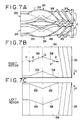
- rotors 24 shown in FIG. 7A which are used in a continuous mixer, are each provided on an outer peripheral surface thereof with a feed screw 35 and a mixing portion 36, the feed screw 35 comprising feed blades for conveying a material to be mixed up to a discharge port (the left-hand side in FIG. 7A), the mixing portion 36 comprising feed blades 38 and return blades 39 for allowing the material to pass through a tip clearance for an inner surface of a mixing chamber and imparting a shear force thereto.
- the feed blades 38 are twisted in a direction to feed the material to be mixed to the discharge port side, while the return blades 39 are twisted in a direction to return the material to the side opposite to the discharge port.
- the blades 38 and 39 are joined together so as to be contiguous to each other at a nearly central part of the mixing portion 36. Consequently, the fill rate of the material which has been conveyed by the feed screw 35 is increased by the blades 38 and 39 in the vicinity of that joined portion, so that a strong shear force is exerted on the material.
- the conventional rotors 4 and 24 are designed so that, when developed about their axes into a planar state, all of their developed shapes are rectilinear. Therefore, the twist angle of each blade is constant in the range from a start point P to a terminal point Q.
- each rotor 24 for a continuous mixer even if their twist angle ⁇ is increased or decreased while maintaining their developed shape in a rectilinear state, it is difficult to take balance between mixing and dispersion of the material to be mixed as is the case with the above.
- the blade is twisted and, in a planarly developed state of the rotor about the axis thereof, the twist angle of the blade varies between a start point and a terminal point of the blade so as to give a substantially non-linear developed shape from the start point to the terminal point of the blade.
- the twist angle of each blade changes in the range from the start point to the terminal point of the blade, the twist angle increases at a certain portion of the blade to enhance the degree of mixing, while the twist angle at the other portion decreases to enhance the degree of dispersion, and thus it is possible to efficiently take balance between mixing and dispersion of the material to be mixed which are taken charge of by one blade.
- a rotor for a batch mixer if the twist angle of at least one of plural blades (say, long and short blades) is varied so as to become smaller gradually from a start point located on an axial end side of the rotor toward a terminal point located on an axially central side thereof, a material flow is generated by the blade portion located on the start point side to enhance the degree of mixing of the material and at the same time a desired material passage quantity in a tip clearance is ensured at the blade portion located on the terminal point side, whereby the degree of dispersion of the material can be enhanced.
- an appropriate control capable of making both mixing and dispersion compatible with each other.
- each long blade is varied so as to become smaller gradually from a start point located on an end side in the rotor axis direction toward a terminal point located on a central side in the same direction and thereafter become larger, the material flow is accelerated not only at the start end-side portion of the long blade but also at the end point-side portion thereof, whereby the mixing performance for the material to be mixed can be improved. Thus, it is desirable to do so.
- a material flow is created by the start point-side portion of each blade concerned to enhance the degree of mixing of the material to be mixed and at the same time a desired material passage quantity is ensured at the terminal point-side portion of the blade, whereby the degree of dispersion of the material can be enhanced.
- an appropriate control can be done in which both mixing and dispersion are compatible with each other.
- FIGS. 1A to 3 illustrate the first embodiment of the present invention.
- FIG. 3 shows an example of a closed batch mixer 1 which adopts rotors according to the present invention.
- the mixer 1 is provided with a chamber 3 having a mixing chamber 2 which is in the shape of eyeglasses holes in section, a pair of right and left rotors 4 inserted rotatably into the mixing chamber 2, a material feed cylinder 6 erected on an upper opening of the chamber 3 and equipped with a hopper 5, and a floating weight 7 inserted into the feed cylinder 6 vertically movably.
- a pneumatic cylinder 8 is connected to the top of the material feed cylinder 6, and a piston 9 installed in the cylinder 8 is connected to the floating weight 7 through a piston rod 10 which extends in an airtight manner through a lower lid of the cylinder 8.
- a discharge port formed in the bottom of the chamber 3 is closed by a drop door 11 which is movable vertically. By opening the drop door 11 the material which has been mixed by only a predetermined time within the mixing chamber 2 can be discharged to the exterior of the mixer.
- FIG. 1A is a plan view of the paired right and left rotors 4, and FIGS. 1B and 1C are developed diagrams obtained by developing the rotors 4 about their axes into a planar state.
- the rotors 4 used in this embodiment are adapted to rotate in directions opposite to each other (arrow "a" directions in FIG. 1A) so that respective opposed inner portions shift downward.
- Each rotor 4 is provided on an outer peripheral surface thereof with long blades 12 and short blades 13 which are for causing the to-be-mixed material to pass through a tip clearance for the inner surface of the mixing chamber 2 and thereby imparting a shear force to the material.
- the long and short blades 12, 13 are axially cut with respect to each other located at circumferentially displaced positions, and twisted in directions opposite to each other.
- Each rotor 4 used in this embodiment has a two-tip section and has a total of four blades, so each short blade 13 is disposed at a circumferential position displaced by nearly a quarter of a circumference with respect to each long blade 12.
- the blades 12 and 13 are arranged in a front-rear replaced manner so as to be in point symmetry with respect to a central point O in FIG. 1A.
- Each short blade 13 is set at a length about 0.1 to 0.5 times that of each long blade 12.
- the blades 12 and 13 are each formed so that a developed shape thereof from a start point thereof located on an end side in the rotor axis direction to a terminal point located on a central side in the same direction is a non-linear curved shape, by continuously changing the twist angle so as to become gradually smaller from the start point P toward the terminal point Q.
- a start point-side portion 14 of the long blade 12 is at an angle larger than the inclination angle of a virtual line L joining the start and terminal points P, Q, while an end point-side portion 15 of the long blade 12 is at an angle smaller than the inclination angle of the virtual line L.
- the twist angle is larger than in a blade having a developed shaped corresponding to the virtual line L, so that a larger material flow 16 than in the case of the said blade can be created at the portion 14, whereby the degree of mixing of the material to be mixed is enhanced.
- each long blade 12 since the twist angle smaller than in the case of the blade having a developed shape corresponding to the virtual line L, a larger material passage quantity in the tip clearance than in the case of the said blade is ensured at the portion 15, whereby the degree of dispersion of the material to be mixed is enhanced.
- each rotor 4 the curved shape of each long blade 12 and the resulting function and effect, both described above, are also true of each short blade 13.
- both mixing performance and dispersing performance for the material to be mixed can be improved in comparison with the blade (conventional blade) having a developed shape corresponding to the virtual line L joining the start and terminal points P, Q in the shortest distance, and there can be made an appropriate control in which both mixing and dispersion for the material to be mixed are compatible with each other.
- the material to be mixed is suppressed from being pushed against an axial end face side of the mixing chamber 2, whereby there is attained an additional effect that the sealing performance for a bearing portion between the chamber 3 and the rotor 4 can be improved.
- the twist angle of the central portion in the rotor axis direction is smaller than in the prior art, when a lumpy material to be mixed such as rubber is to be introduced into the mixing chamber 2, the engagement of the material with the blades 12 and 13 is improved, whereby there is attained an additional effect that the material feed time becomes shorter and the productivity can be improved.
- the dispersing performance for the material can be improved by extending the front end portion of the long blade 12 closer to the short blade 13.
- each rotor 4 shown in FIG. 1A only one of the long and short blades 12, 13 may be curved, and the concave-convex direction of the curved shape may be made opposite to the illustrated direction.
- FIG. 2A shows a modification of a pair of right and left rotors 4 used in the above batch mixer 1.
- the twist angle of each long blade 12 varies so as to once become smaller gradually from a start point P located on an end side in the rotor axis direction toward a terminal point Q located on a central side m the same direction and thereafter become larger.
- a developed shape of the long blade 2 is a generally S shape constituted by a concavely curved portion and a convexly curved portion both contiguous to each other as seen from the central portion of the mixing chamber 2 and having both-end portions 17 of a relatively large twist angle and a central portion 18 of a relatively small twist angle.
- a material flow 16 is accelerated at the end portion 17 on a start end P side of the long blade 12 having a large twist angle and the material passage quantity in a tip clearance is increased at the central portion 18 where the twist angle is small, whereby the mixing and dispersion of the material to be mixed are improved in a well-balanced state.
- the developed shape of the long blade 12 may be made into an inverted S shape in which the concave and convex direction of the long blade is opposite to that indicated with a solid line.
- the material dispersing performance is ensured at both end portions of the long blade 12 and the material mixing performance ensured at the central portion.
- FIGS. 4A to 4C and FIG. 5 illustrate the second embodiment of the present invention.
- FIG. 5 shows an example of a biaxial continuous mixer 21 which adopts rotors according to the present invention.
- the mixer 21 is provided with a chamber 23 having a mixing chamber 22 which is in the shape of eyeglasses holes in section, a pair of right and left rotors 24 inserted rotatably into the mixing chamber 22, and a gate device 25 installed axially centrally of the chamber 23.
- a feed port 26 for feeding a material to be mixed which is in the form of, for example, a powder or pellets to the mixing chamber 22, with a hopper (not shown) being connected to the feed port 26.
- a vent hole 27 for removing a gas which has been mixed into the material at the time of material feed and a gas which has been generated during mixing or for post-addition of additives such as inorganic fillers.
- a discharge port 28 for discharging the material after mixing, which is in a melted state, to the exterior of the chamber 23.
- a post-processing apparatus such as a pelletizer is connected to the discharge port 28 through a pressurizing means such as a gear pump or an extruder (neither shown).
- the gate device 25 which causes a pair of upper and lower gate plates 29 to move toward or away from an outer peripheral portion of each rotor 24 radially from the outside to adjust the flow rate of the material to be mixed.
- the mixing chamber 22 in the chamber 23 is partitioned into two mixing stages consisting of a first stage 31 located on an upstream side and a second stage 32 located on a downstream side.
- the rotors 24 are adapted to rotate in directions (arrow "a" directions in FIG. 4A) different from each other so that respective opposed inner portions move downward and are each provided, successively from the upstream side, with a first feed portion 33 and a first mixing portion 34 both positioned in the first stage 31, a second feed portion 35 and a second mixing portion 36 both positioned in the second stage 32, and a discharge portion 37 which is contiguous to the second mixing portion 36 and which comprises parallel blades.
- the mixing portions 34 and 36 are for applying a strong shear force to the material to be mixed to mix and melt the material and are each provided with a feed blade 38 which is twisted in a direction to extrude the material to the downstream side with rotation of the rotor and a return blade 39 which is twisted in a direction to push back the material to the upstream side with the said rotation.
- the material is mixed in the following manner by the above biaxial continuous mixer 1. First, the material is introduced into the mixer through the feed port 26. Then, in the first stage 31, the material is fed downstream by the first feed portion 33 and undergoes a large shear force when passing through a tip clearance between a tip portion of the first mixing portion 34 and an inner surface of the mixing chamber 22, resulting in that the material melts due to self-heat generation.
- the molten resin material while being adjusted the degree of mixing by the degree of opening of the gate device 25, reaches the second feed portion 35 in the second stage 32, then is conveyed to the second mixing portion 36 by a screw action of the feed portion 35, in which portion 36 the material is further mixed and melted.
- the material after mixing which has passed through the second mixing portion 36 is scraped out downward by the succeeding discharge portion 37 and is discharged from the discharge port 28 to the exterior of the chamber 2, then is conveyed to a post-processing apparatus.
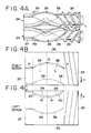
- FIG. 4A is a plan view of the second mixing portions 36 of the paired right and left rotors 24 and FIGS. 4B and 4C are developed diagrams obtained by developing the second mixing portions 36 about their axes into a planar state.
- the feed blade 38 is twisted in a direction to feed the to-be-mixed material to the discharge port 28 side, while the return blade 39 is twisted in a direction to return the material to the side opposite to the discharge port 28.
- the blades 38 and 39 are joined together so as to be contiguous to each other nearly centrally of the second mixing portion 36.
- the right and left rotors 24 are arranged in a right-left replaced state so that the blades 38 and 39 are arranged axisymmetrically with respect to a transverse central line of the mixing chamber 22.
- the L/D value of the feed blade 38 and that of the return blade 39 are preset so as to be approximately equal to each other.
- the twist angle of each of the blades 38 and 39 is varied continuously so as to become smaller gradually from a start point P on an end side in the rotor axis direction toward a terminal point Q on a central side in the same direction, whereby the blades 38 and 39 each assume a non-linear curved shape in its developed state from the start point P to the terminal point Q.
- a start point-side portion 40 of each of the blades 38 and 39 is at an angle larger than the inclination angle of a virtual line L joining the start and terminal points P, Q, while a terminal point-side portion 41 of each of the blades 38 and 39 is at an angle smaller than the inclination angle of the virtual line L.
- the twist angle is larger than in the case of a blade having a developed shape corresponding to the virtual line L, so that the material mixing area becomes larger and the degree of material mixing is enhanced.
- the twist angle is smaller than in the case of a blade having a developed shape corresponding to the virtual line L, a larger material passage quantity than in the case of the said blade is ensured at the portion 41, whereby the degree of material dispersion is enhanced.
- both material mixing performance and dispersing performance can be improved in comparison with that in the use of the blade (conventional blade) having a developed shape corresponding to the virtual line L and there can be made an appropriate control in which both mixing and dispersion for the material are compatible with each other.
- the mixing portion 36 is applicable not only to a twice mixing type continuous mixer but also to a single mixing type continuous mixer not provided with the gate device 25, as well as rotors used therein.
- the number of blades in the circumferential direction of each rotor is not limited to two. Three or more blades may be present in the circumferential direction. Likewise, the number of blades arranged separately in the axial direction of each rotor may be three or more. Besides, the present invention is applicable not only to an intermesh type rotor but also to a tangential type rotor, further to a uniaxial type rotor.
- the twist angle of each blade varies continuously at any axial portion of the blade (a curved developed shape)
- the twist angle of a blade may vary discontinuously insofar as the blade is recognized as being substantially non-linear in a developed shape thereof from its start point to terminal point.
- the "substantially non-linear" as referred to herein indicates a state in which a developed state of a single blade having both start and terminal points is a slightly bypassed shape in the circumferential direction when seen from a straight line of the shortest distance extending from the start to the terminal point.
- the bypass may be a curved line or a polygonal line.
- a rotor for a mixer having a twisted blade, wherein, in a planarly developed state of the rotor about its axis, the twist angle of the blade varies between a start point and a terminal point of the blade so as to give a substantially non-linear developed shape from the start point to the terminal point of the blade. It is possible to take balance efficiently between mixing and dispersion for a material to be mixed which mixing and dispersion are taken charge of by a single blade.
Landscapes
- Engineering & Computer Science (AREA)
- Mechanical Engineering (AREA)
- Processing And Handling Of Plastics And Other Materials For Molding In General (AREA)
- Mixers Of The Rotary Stirring Type (AREA)
Abstract
Description
Claims (8)
- A rotor for a mixer, comprising a blade formed on an outer peripheral surface of said rotor, said blade being twisted relative to a rotor axis direction, wherein, in a planarly developed state of the rotor about the axis thereof, the twist angle of said blade varies between a start point and a terminal point of said blade so as to give a substantially non-linear developed shape from said start point to said terminal point of said blade.
- A rotor for a batch mixer, comprising a plurality of blades formed on an outer peripheral surface of said rotor, said blades being twisted relative to a rotor axis direction, wherein, in a planarly developed state of said rotor about the axis thereof, the twist angle of at least one of said blades varies between a start point and a terminal point of the blade so as to give a substantially non-linear developed shape from said start point to said terminal point of the blade.
- A rotor for a batch mixer according to claim 2, wherein the twist angle of at least one of said blades varies so as to become smaller gradually from a start point of the blade located on an end side in the rotor axis direction toward a terminal point located on a central side in said direction.
- A rotor for a batch mixer according to claim 3, wherein the twist angle of at least one of said blades once becomes smaller gradually from said start point toward said terminal point and thereafter becomes larger.
- A rotor for a continuous mixer, comprising:a feed blade formed on an outer peripheral surface of said rotor so as to be twisted relative to a rotor axis direction;a return blade formed on the outer peripheral surface of the rotor so as to be twisted relative to said rotor axis direction,wherein, in a planarly developed state of said rotor about the axis thereof, the twist angle of one or both of said feed blade and said return blade varies between a start point and a terminal point of the blade or blades so as to give a substantially non-linear developed shape from said start point to said terminal point of the blade or blades.
- A rotor for a continuous mixer according to claim 5, wherein the twist angle of one or both of said feed blade and said return blade varies so as to become smaller gradually from a start point located on an end side in the rotor axis direction toward a terminal point located on a central side in said direction.
- A mixer comprising:a chamber having a mixing chamber; andthe rotor described in any of claims 1 to 6, said rotor being inserted into said mixing chamber rotatably and having on its outer peripheral surface a blade which is twisted relative to the rotor axis direction,wherein a material to be mixed is allowed to pass through a tip clearance formed between an inner surface of said mixing chamber and a top portion of said blade and a shear force is thereby exerted on said material.
- A rotor for a mixer, inserted rotatably into a mixing chamber so as to form a tip clearance between a top portion of a blade and an inner surface of said mixing chamber, said blade being formed on an outer peripheral surface of said rotor and twisted relative to a rotor axis direction, with a material to be mixed being allowed to pass through said tip clearance and a shear force thereby exerted on said material,
characterized in that, in a planarly developed state of the rotor about the axis thereof, the twist angle of said blade varies between a start point and a terminal point of said blade so as to give a substantially non-linear developed shape from the start point to the terminal point of said blade.
Applications Claiming Priority (2)
| Application Number | Priority Date | Filing Date | Title |
|---|---|---|---|
| JP5457099 | 1999-03-02 | ||
| JP11054570A JP2000246731A (en) | 1999-03-02 | 1999-03-02 | Kneading rotor and kneading machine having the same |
Publications (2)
| Publication Number | Publication Date |
|---|---|
| EP1033217A2 true EP1033217A2 (en) | 2000-09-06 |
| EP1033217A3 EP1033217A3 (en) | 2001-03-14 |
Family
ID=12974363
Family Applications (1)
| Application Number | Title | Priority Date | Filing Date |
|---|---|---|---|
| EP00102763A Withdrawn EP1033217A3 (en) | 1999-03-02 | 2000-02-10 | Rotor for a mixer and mixer having the same |
Country Status (5)
| Country | Link |
|---|---|
| EP (1) | EP1033217A3 (en) |
| JP (1) | JP2000246731A (en) |
| KR (1) | KR20010014518A (en) |
| CN (1) | CN1265936A (en) |
| AU (1) | AU735360B2 (en) |
Cited By (5)
| Publication number | Priority date | Publication date | Assignee | Title |
|---|---|---|---|---|
| US6811295B2 (en) * | 2000-04-26 | 2004-11-02 | Kabushiki Kaisha Kobe Seiko Sho | Batch mixer and a mixing rotor for the same |
| EP1661679A1 (en) * | 2004-11-18 | 2006-05-31 | Kabushiki Kaisha Kobe Seiko Sho | Batch mixer and mixing rotor used in the same |
| RU2472616C1 (en) * | 2009-01-19 | 2013-01-20 | Кабусики Кайся Кобе Сейко Се | Mixing rotor, intermittent mixing machine and method of mixing materials |
| US9687797B2 (en) | 2012-12-26 | 2017-06-27 | Bridgestone Corporation | Kneading device |
| EP3106278A4 (en) * | 2014-02-13 | 2017-11-15 | Kabushiki Kaisha Kobe Seiko Sho (Kobe Steel, Ltd.) | Continuous kneading device |
Families Citing this family (7)
| Publication number | Priority date | Publication date | Assignee | Title |
|---|---|---|---|---|
| US6494607B2 (en) * | 2001-05-04 | 2002-12-17 | Farrel Corporation | Four wing, non-intermeshing rotors for synchronous drive to provide improved dispersive and distributive mixing in internal batch mixers |
| DE10321350B4 (en) * | 2003-05-13 | 2005-04-21 | Lurgi Ag | mixing device |
| JP5027717B2 (en) * | 2008-04-08 | 2012-09-19 | 株式会社モリヤマ | Twin screw extruder |
| JP5388373B2 (en) * | 2011-05-30 | 2014-01-15 | 株式会社日本製鋼所 | Material kneading apparatus and material kneading method |
| CN102350746A (en) * | 2011-09-14 | 2012-02-15 | 昆山科信橡塑机械有限公司 | Non-meshing double-mixing rotor for continuous internal mixer |
| JP5792650B2 (en) | 2012-01-31 | 2015-10-14 | 株式会社神戸製鋼所 | Kneading rotor and hermetic kneading machine including the same |
| JP6013314B2 (en) * | 2013-12-20 | 2016-10-25 | 株式会社神戸製鋼所 | Calibration method for thrust load measuring device of closed kneader |
Family Cites Families (10)
| Publication number | Priority date | Publication date | Assignee | Title |
|---|---|---|---|---|
| GB376184A (en) * | 1931-03-07 | 1932-07-07 | Albert Lasch | Improvements in and relating to mixing, kneading and like machines |
| NL131340C (en) * | 1963-11-27 | 1900-01-01 | ||
| DE1679879B1 (en) * | 1967-05-03 | 1971-05-13 | Werner & Pfleiderer | KNEDE AND MIXING MACHINE FOR PLASTIC MASSES |
| JPS5931369B2 (en) * | 1980-02-16 | 1984-08-01 | 株式会社神戸製鋼所 | Rotor of closed type kneading device |
| US4474475A (en) * | 1982-12-30 | 1984-10-02 | Masao Moriyama | Mixing apparatus |
| JPS6244409A (en) * | 1985-08-22 | 1987-02-26 | Kobe Steel Ltd | Enclosed type kneading machine |
| US4893936A (en) * | 1986-05-16 | 1990-01-16 | Farrel Corporation | Mixing machine with non-intermeshing pair of rotors driven solely at the same rotor speed in opposite directions and having a predetermined rotational alignment relationship between the two counter-rotating rotors |
| DE4129108A1 (en) * | 1991-09-02 | 1993-03-04 | Continental Ag | DEVICE FOR PRODUCING RUBBER COMPOUNDS |
| EP0595112B1 (en) * | 1992-10-26 | 1998-02-04 | Bridgestone Corporation | Screw for double-shaft extruding device and double-shaft extruding device |
| IT1303885B1 (en) * | 1998-11-30 | 2001-03-01 | Techint Spa | ROTOR FOR MIXING MACHINES OF ELASTOMERS AND SIMILAR WITH INPUT ANGLE IN THE MIXTURE VARIOUS ALONG THE DEVELOPMENT OF AT LEAST ONE OF THE |
-
1999
- 1999-03-02 JP JP11054570A patent/JP2000246731A/en active Pending
-
2000
- 2000-02-10 EP EP00102763A patent/EP1033217A3/en not_active Withdrawn
- 2000-02-29 KR KR1020000010106A patent/KR20010014518A/en not_active Ceased
- 2000-03-01 AU AU19558/00A patent/AU735360B2/en not_active Ceased
- 2000-03-02 CN CN00103715A patent/CN1265936A/en active Pending
Cited By (8)
| Publication number | Priority date | Publication date | Assignee | Title |
|---|---|---|---|---|
| US6811295B2 (en) * | 2000-04-26 | 2004-11-02 | Kabushiki Kaisha Kobe Seiko Sho | Batch mixer and a mixing rotor for the same |
| EP1661679A1 (en) * | 2004-11-18 | 2006-05-31 | Kabushiki Kaisha Kobe Seiko Sho | Batch mixer and mixing rotor used in the same |
| US7854542B2 (en) | 2004-11-18 | 2010-12-21 | Kobe Steel, Ltd. | Batch mixer and mixing rotor used in the same |
| AU2005229749B2 (en) * | 2004-11-18 | 2011-03-24 | Kabushiki Kaisha Kobe Seiko Sho (Kobe Steel Ltd) | Batch mixer and mixing rotor used in the same |
| RU2472616C1 (en) * | 2009-01-19 | 2013-01-20 | Кабусики Кайся Кобе Сейко Се | Mixing rotor, intermittent mixing machine and method of mixing materials |
| US9687797B2 (en) | 2012-12-26 | 2017-06-27 | Bridgestone Corporation | Kneading device |
| EP3106278A4 (en) * | 2014-02-13 | 2017-11-15 | Kabushiki Kaisha Kobe Seiko Sho (Kobe Steel, Ltd.) | Continuous kneading device |
| US10449498B2 (en) | 2014-02-13 | 2019-10-22 | Kobe Steel, Ltd. | Continuous kneading device |
Also Published As
| Publication number | Publication date |
|---|---|
| AU1955800A (en) | 2000-09-28 |
| KR20010014518A (en) | 2001-02-26 |
| JP2000246731A (en) | 2000-09-12 |
| AU735360B2 (en) | 2001-07-05 |
| CN1265936A (en) | 2000-09-13 |
| EP1033217A3 (en) | 2001-03-14 |
Similar Documents
| Publication | Publication Date | Title |
|---|---|---|
| EP1028839B1 (en) | Screw extruder with various dispersive mixing elements | |
| US4652138A (en) | Single screw kneading extruder | |
| US6136246A (en) | Screw extruder with improved dispersive mixing elements | |
| US3941535A (en) | Extrusion device | |
| JP4024976B2 (en) | Closed kneader | |
| JP2905418B2 (en) | Kneading machine | |
| AU735360B2 (en) | Rotor for a mixer and mixer having the same | |
| US3870284A (en) | Extruder screws | |
| AU775556B2 (en) | A batch mixer and a mixing rotor for the same | |
| JPS60202723A (en) | Continuous type mixing and shearing roll mill | |
| CN101107116B (en) | Extruder with feedback device | |
| US4444507A (en) | Apparatus and method for melting and conveying plasticated material | |
| JP2001009830A (en) | Continuous kneader, its kneading method and rotor of continuous kneader | |
| GB2041284A (en) | Plasticising and impelling Particulate Materials | |
| JPH11188249A (en) | Pressurized kneader | |
| US6062717A (en) | Chopper mixing screw | |
| US20240208106A1 (en) | Granulator, kneading adjustment mechanism, and method of manufacturing resin pellets | |
| JP2002526280A (en) | Simultaneously rotating twin screw extruder | |
| US12539658B2 (en) | Resin extruder , rotor-type screw shaped so that the size of the gap between the screw and the inner surface of the cylinder holding the screw changes, and resin manufacturing method | |
| CN103429408B (en) | Continuous mixer | |
| EP2517852B1 (en) | Kneading segment, and kneading apparatus comprising such a segment | |
| US6224251B1 (en) | Continuous kneading machine | |
| JP7629297B2 (en) | Twin screw mixer and mixing method of mixed materials | |
| JPH021650B2 (en) | ||
| WO2025069520A1 (en) | Screw for twin-shaft non-meshing extruder and twin-shaft non-meshing extruder |
Legal Events
| Date | Code | Title | Description |
|---|---|---|---|
| PUAI | Public reference made under article 153(3) epc to a published international application that has entered the european phase |
Free format text: ORIGINAL CODE: 0009012 |
|
| 17P | Request for examination filed |
Effective date: 20000210 |
|
| AK | Designated contracting states |
Kind code of ref document: A2 Designated state(s): DE FR GB IT |
|
| AX | Request for extension of the european patent |
Free format text: AL;LT;LV;MK;RO;SI |
|
| PUAL | Search report despatched |
Free format text: ORIGINAL CODE: 0009013 |
|
| AK | Designated contracting states |
Kind code of ref document: A3 Designated state(s): AT BE CH CY DE DK ES FI FR GB GR IE IT LI LU MC NL PT SE |
|
| AX | Request for extension of the european patent |
Free format text: AL;LT;LV;MK;RO;SI |
|
| RIC1 | Information provided on ipc code assigned before grant |
Free format text: 7B 29B 7/18 A, 7B 29B 7/46 B, 7B 29B 7/48 B, 7B 30B 11/24 B, 7B 01F 7/08 B |
|
| 17Q | First examination report despatched |
Effective date: 20010531 |
|
| AKX | Designation fees paid |
Free format text: DE FR GB IT |
|
| STAA | Information on the status of an ep patent application or granted ep patent |
Free format text: STATUS: THE APPLICATION IS DEEMED TO BE WITHDRAWN |
|
| 18D | Application deemed to be withdrawn |
Effective date: 20011211 |