EP1033195A1 - Spannbacke - Google Patents
Spannbacke Download PDFInfo
- Publication number
- EP1033195A1 EP1033195A1 EP00102945A EP00102945A EP1033195A1 EP 1033195 A1 EP1033195 A1 EP 1033195A1 EP 00102945 A EP00102945 A EP 00102945A EP 00102945 A EP00102945 A EP 00102945A EP 1033195 A1 EP1033195 A1 EP 1033195A1
- Authority
- EP
- European Patent Office
- Prior art keywords
- clamping
- insert
- jaw
- recess
- clamping jaw
- Prior art date
- Legal status (The legal status is an assumption and is not a legal conclusion. Google has not performed a legal analysis and makes no representation as to the accuracy of the status listed.)
- Withdrawn
Links
- 238000005219 brazing Methods 0.000 claims description 2
- 238000003754 machining Methods 0.000 claims description 2
- 230000002441 reversible effect Effects 0.000 abstract 1
- 238000004519 manufacturing process Methods 0.000 description 4
- 230000005540 biological transmission Effects 0.000 description 3
- 238000004026 adhesive bonding Methods 0.000 description 2
- 210000000078 claw Anatomy 0.000 description 2
- 238000005553 drilling Methods 0.000 description 2
- 238000005476 soldering Methods 0.000 description 2
- 230000015572 biosynthetic process Effects 0.000 description 1
- 238000007373 indentation Methods 0.000 description 1
- 238000003801 milling Methods 0.000 description 1
Images

Classifications
-
- B—PERFORMING OPERATIONS; TRANSPORTING
- B23—MACHINE TOOLS; METAL-WORKING NOT OTHERWISE PROVIDED FOR
- B23B—TURNING; BORING
- B23B31/00—Chucks; Expansion mandrels; Adaptations thereof for remote control
- B23B31/02—Chucks
- B23B31/10—Chucks characterised by the retaining or gripping devices or their immediate operating means
- B23B31/12—Chucks with simultaneously-acting jaws, whether or not also individually adjustable
- B23B31/16—Chucks with simultaneously-acting jaws, whether or not also individually adjustable moving radially
- B23B31/1627—Details of the jaws
- B23B31/16275—Form of the jaws
Definitions
- the invention relates to a clamping jaw for clamping devices from Machine tools, in particular for machining Workpieces with at least one of a given Assigned clamping diameter range, at least one tooth Clamping surface.
- clamping jaws which are clamped to the respective clamping diameter be turned out and for clamping the workpiece on an already machined surface are used, are jaws with a or known several tension levels, in which for secure clamping of the Workpieces are formed on unprocessed surfaces tooth-like projections.
- Claw jaws with one or more teeth on the single clamping surface, these teeth also being arranged on interchangeable clamping inserts can.
- Clamping jaw systems for clamping devices are known in which the Teeth are formed by inserts inserted into recesses, the Inserts can be attached by screws. Especially with those that occur Such systems are not sufficiently safe at high speeds. In addition, the systems are only known for single-stage jaws.
- the invention is based on the object assigned to a particular for tensioning devices of machine tool clamping jaw of the initially described kind with at least one a predetermined clamping diameter range to develop at least one tooth having clamping surface in such a way that it can be manufactured at low cost despite universal use possibility and reliable clamping within the predetermined clamping range guaranteed.
- the solution to this problem by the invention is characterized in that the tooth is formed on the lateral surface of a cylindrical insert which is captively arranged in a correspondingly cylindrical recess formed on the central axis and / or symmetrically on both sides of the central axis and open to the clamping surface , which is formed from the end face of the clamping jaw approximately at right angles to the end face in the clamping jaw such that the insert protrudes at least with its tooth from the clamping surface and is encompassed on a wrap angle of more than 180 ° from the wall of the recess.
- the inventive design of the tooth on the lateral surface of a cylindrical insert and the inventive arrangement of this insert in one on the central axis and / or symmetrical on both sides of the central axis trained recess the actual jaw can be inexpensive getting produced.
- hardening of the clamping jaw is not necessary, because the transmission of the clamping force only in the area of the Inserts are carried out, which in turn are manufactured and hardened at low cost can, because it is simple parts that can be produced with little effort are.
- the shape and number of clamping surfaces can also be customized Purpose to be adjusted as the location and number of each with inserts with at least one tooth. It is therefore possible for both special clamping inserts certain as well as universally applicable clamping jaws inexpensive to manufacture according to the invention.
- the cross section of the cylindrical inserts as well as the corresponding ones Recesses in the jaw can have any shape for example in the manner of a polygon.
- To manufacture both the inserts as well as the recesses is simplified according to another Feature of the invention proposed the use and the associated Form recess with a circular cylindrical basic shape.
- the recesses can be economically priced by drilling or milling getting produced.
- teeth arranged at least in one row.
- Such teeth can thus both in a row one behind the other also in several, preferably parallel rows on the lateral surface of the Be trained.
- the jaw according to the invention in the manner of one on a base jaw step jaw rotatable by 180 ° and displaceable in the radial direction several clamping surfaces on different clamping diameters is proposed, is proposed with the invention, in the field of everyone Rake surface one on the central axis and / or symmetrically on both sides of the To form the central axis of the recess.
- the in these recesses arranged inserts thus transmit the clamping force either in the area of Center axis of the clamping jaw and / or symmetrical at a distance from both sides this central axis from the clamping jaw to the workpiece.
- the depth of the recesses is made with one or more times the length of all recesses identical use trained. This way it is possible despite different dimensions of the clamping surfaces in the axial direction, that is to be able to use the same inserts parallel to the axis of rotation, accordingly can be produced in larger numbers and thus more cheaply and in a number corresponding to the respective depth of the recess in the Recess are used.
- each insert can be replaced by a detachable connection arranged in the respective recess, in particular by clamping, gluing or soldering.
- the recesses as holes when on the clamping device arranged and under clamping force jaws in this bring in. Even slight deformations of the jaws and die Clamp driving gear parts of the chuck are on this Way balanced.
- the invention proposes that the inserts are fixed in the recesses by means of brazing.
- Such an attachment has the advantage that even with multi-stage jaws and thus unloaded Deployment at the high speeds that occur Stakes is excluded.
- the power transmissions significantly improved.
- the inserts over the entire surface Support recesses and thus tilting moments or an indentation with the Time to be avoided. The forces become even over large areas distributed.
- the invention proposes that the inserts are inserted non-rotatably in the recesses, so that when the Basic settings were not made in recesses and fixing of the inserts are changeable.
- the jaw body is 10 provided on its rear side according to FIG. 2 with a longitudinal groove 11; on both sides of this groove 11 are on the back of the jaw body 10 Serrations 12 formed, with the help of the jaw over corresponding gears attached to a base jaw, not shown can be.
- the clamping jaw can be in the serrations 12 appropriate steps in the longitudinal direction attached to the base jaw and also be turned by 180 ° in relation to the base jaw.
- the attachment of the Clamping jaw on the base jaw is not done by two on the drawing illustrated jaw fastening screws.
- the jaw body 10 For the passage of the shaft of this Jaw mounting screws is the jaw body 10 with two Through holes 13 provided. At these through holes 13 closes each have an enlarged bore 14 for the head of the Cheek mounting screw, as best shown in the longitudinal section of FIG. 3 is recognizable.
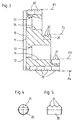
- the clamping jaw designed as a so-called step jaw is shown in the Embodiment provided with a total of four clamping surfaces F1 to F4, which in Fig. 3 are marked.
- a total of seven clamping diameter ranges D1 to D7 cover that in Fig. 1 by the respective mean diameter of each Clamping range are marked.
- Inserts 20 serve as a cylindrical body with the workpiece Shell surface in a row of teeth 21 are executed.
- This Inserts 20 have a circular cylindrical cross section in the exemplary embodiment and three teeth 21, the formation of which can best be seen in FIG. 5.
- the Flanks of these flattened teeth 21 close when Embodiment an angle of 90 ° to each other; the teeth 21 can naturally also have a different shape. This is enough in some cases the arrangement of a tooth 21 on the outer surface of the insert 20. In in other cases, more teeth 21 can be preferably parallel in several rows running to one another on the lateral surface of the insert 20 be trained.
- the inserts 20 are each captive in a recess 15 of the Jaw body 10 arranged, each of the end face 16 of the Cheek body 10 extends at right angles to this end face 16 and to respective clamping surface F1 to F4 is open, so that the teeth 21 of the insert 20th from the recess 15 in the jaw body 10 in the direction of the respective Protruding clamping surface F1 to F4, as is particularly the case in the middle part of the Fig. 3 and in the left half of Fig. 2 can be seen.
- 1 in particular shows that here each insert 20 on a wrap angle of more than 180 ° from the wall of the recess 15 is embraced, so that the use in radial direction can not fall out of the respective recess 15.
- each insert 20 is, for example, by Clamping, gluing or soldering held captive.
- the clamping surfaces F1 to F4 in the illustrated embodiment either by one on the Center axis M of the jaw body 10 arranged insert 20 or by two Inserts 20 formed symmetrically on both sides of the central axis M are arranged.
- a clamping surface form three inserts 20, one on the central axis M and two are arranged symmetrically on both sides of the central axis M.
- FIG. 3 shows that for Forming the clamping surfaces F2 and F3 each have an insert 20 in the associated one Recess 15 is arranged, whereas the clamping surface F1 by two and Clamping surface F4 by four arranged one behind the other in the recesses 15 Inserts 20 is formed.
- the recesses 15 as bores when arranged on the tensioning device and under tension Clamping jaws are inserted into this. This ensures that the teeth 21 of the inserts 20 in the case of clamping jaws under tension prescribed position.
Landscapes
- Engineering & Computer Science (AREA)
- Mechanical Engineering (AREA)
- Gripping On Spindles (AREA)
- Saccharide Compounds (AREA)
- Jigs For Machine Tools (AREA)
- Gripping Jigs, Holding Jigs, And Positioning Jigs (AREA)
Abstract
Description
- Fig. 1
- eine Stirnansicht einer als Stufenbacke ausgebildeten Spannbacke,
- Fig. 2
- eine Draufsicht auf die Spannbacke nach Fig. 1,
- Fig. 3
- einen Längsschnitt durch die Spannbacke gemäß der Schnittlinie III-III in Fig. 1,
- Fig. 4
- eine vergrößert dargestellte Stirnansicht eines der verwendeten Einsätze und
- Fig. 5
- eine Seitenansicht des Einsatzes nach Fig. 4.
- 10
- Backenkörper
- 11
- Nut
- 12
- Spitzverzahnung
- 13
- Durchgangsbohrung
- 14
- Bohrung
- 15
- Ausnehmung
- 16
- Stirnfläche
- 20
- Einsatz
- 21
- Zahn
- D1 bis D7
- Spanndurchmesserbereich
- F1 bis F4
- Spannfläche
- M
- Mittelachse
Claims (10)
- Spannbacke für Spanneinrichtungen von Werkzeugmaschinen, insbesondere für eine spanabhebende Bearbeitung von Werkstücken, mit mindestens einer einem vorgegebenen Spanndurchmesserbereich (D1 bis D7) zugeordneten, mindestens einen Zahn (21) aufweisenden Spannfläche (F1 bis F4),
dadurch gekennzeichnet,
daß der Zahn (21) an der Mantelfläche eines zylindrischen Einsatzes (20) ausgebildet ist, der unverlierbar in einer entsprechend zylindrischen, auf der Mittelachse (M) und/oder symmetrisch zu beiden Seiten der Mittelachse (M) ausgebildeten und zur Spannfläche (F1 bis F4) offenen Ausnehmung (15) angeordnet ist, die von der Stirnfläche (16) des Backenkörpers (10) ausgehend etwa rechtwinklig zur Stirnfläche (16) derart im Backenkörper (10) ausgebildet ist, daß der Einsatz (20) zumindest mit seinem Zahn (21) aus der Spannfläche (F1 bis F4) herausragt und auf einem Umschlingungswinkel von mehr als 180° von der Wand der Ausnehmung (15) umfaßt ist. - Spannbacke nach Anspruch 1, dadurch gekennzeichnet, daß der Einsatz (20) und die zugehörige Ausnehmung (15) mit einer kreiszylindrischen Grundform ausgebildet sind.
- Spannbacke nach Anspruch 1 oder 2, dadurch gekennzeichnet, daß der Einsatz (20) mit mehreren, mindestens in einer Reihe angeordneten Zähnen (21) versehen ist.
- Spannbacke nach mindestens einem der Ansprüche 1 bis 3 mit mehreren, auf unterschiedlichen Spanndurchmessern liegenden Spannflächen (F1 bis F4), dadurch gekennzeichnet, daß im Bereich jeder Spannfläche (F1 bis F4) eine auf der Mittelachse (M) und/oder symmetrisch zu beiden Seiten der Mittelachse (M) liegende Ausnehmung (15) ausgebildet ist.
- Spannbacke nach Anspruch 4, dadurch gekennzeichnet, daß die Tiefe der Ausnehmungen (15) mit dem Ein- oder Mehrfachen der Länge des für sämtliche Ausnehmungen (15) identischen Einsatzes (20) ausgebildet ist.
- Spannbacke nach mindestens einem der Ansprüche 1 bis 5, dadurch gekennzeichnet, daß der Einsatz (20) durch eine lösbare Verbindung auswechselbar in der jeweiligen Ausnehmung (15) angeordnet ist.
- Spannbacke nach mindestens einem der Ansprüche 1 bis 5, dadurch gekennzeichnet, daß der Einsatz (20) durch Hartlöten in der jeweiligen Ausnehmung befestigt ist.
- Spannbacke nach einem der vorhergehenden Ansprüche, dadurch gekennzeichnet, daß der Einsatz (20) unverdrehbar in der jeweiligen Ausnehmung (15) eingesetzt ist.
- Spannbacke nach mindestens einem der vorhergehenden Ansprüche, dadurch gekennzeichnet, daß der Einsatz (20) sich entlang der in der Ausnehmung (15) befindlichen zylindrischen Mantelfläche vollflächig an der Spannbacke abstützt.
- Spannbacke nach mindestens einem der vorhergehenden Ansprüche, dadurch gekennzeichnet, daß die Ausnehmungen (15) als Bohrungen bei auf der Spanneinrichtung angeordneten und unter Spannkraft stehenden Spannbacken in den Backenkörper (10) eingebracht werden.
Applications Claiming Priority (2)
| Application Number | Priority Date | Filing Date | Title |
|---|---|---|---|
| DE29903520U | 1999-02-26 | ||
| DE29903520U DE29903520U1 (de) | 1999-02-26 | 1999-02-26 | Spannbacke |
Publications (1)
| Publication Number | Publication Date |
|---|---|
| EP1033195A1 true EP1033195A1 (de) | 2000-09-06 |
Family
ID=8070033
Family Applications (1)
| Application Number | Title | Priority Date | Filing Date |
|---|---|---|---|
| EP00102945A Withdrawn EP1033195A1 (de) | 1999-02-26 | 2000-02-14 | Spannbacke |
Country Status (4)
| Country | Link |
|---|---|
| EP (1) | EP1033195A1 (de) |
| JP (1) | JP2000246568A (de) |
| DE (1) | DE29903520U1 (de) |
| WO (1) | WO2000051769A1 (de) |
Families Citing this family (5)
| Publication number | Priority date | Publication date | Assignee | Title |
|---|---|---|---|---|
| DE10035406C2 (de) * | 2000-07-19 | 2002-07-18 | Lic Tec Ag Cham | Aufsatzbacke für Spannfutter |
| CN103551868B (zh) * | 2013-10-18 | 2017-11-14 | 安庆帝伯粉末冶金有限公司 | 一种防止气门座圈倒角加工反向的面板装置 |
| CN104551754A (zh) * | 2014-11-26 | 2015-04-29 | 哈尔滨汽轮机厂有限责任公司 | 一种燃气轮机压气机承力缸加工用支撑夹紧装置 |
| KR102478391B1 (ko) * | 2022-04-22 | 2022-12-16 | (주)유앤아이테크 | Cnc 선반용 공작물 고정 장치 및 이의 제조 방법 |
| KR102721687B1 (ko) * | 2023-11-21 | 2024-10-24 | 켄코아에어로스페이스(주) | 바이스 보조 장치 |
Citations (7)
| Publication number | Priority date | Publication date | Assignee | Title |
|---|---|---|---|---|
| US1844616A (en) * | 1926-07-03 | 1932-02-09 | Lucius E Whiton | Jaw for lathe chucks, etc. |
| FR1095483A (fr) * | 1953-12-07 | 1955-06-03 | Mors doux pour mandrins de tours, aléseuses, fraiseuses et autres organes analogues | |
| US2778652A (en) * | 1955-02-24 | 1957-01-22 | Ridge Tool Co | Chuck jaws |
| US2926922A (en) * | 1958-02-14 | 1960-03-01 | Vermette Howard | Chuck construction |
| DE2524327A1 (de) * | 1975-06-02 | 1976-12-16 | Richard Goltz | Zusatzvorrichtung fuer ein spannfutter o.dgl. |
| DE3122876A1 (de) * | 1981-06-10 | 1982-12-30 | Fritz Schunk GmbH Fabrik für Spannwerkzeuge, 7128 Lauffen | Greiferbacken fuer backenfutter an werkzeugmaschinen |
| DE3810854A1 (de) * | 1988-03-30 | 1989-10-19 | Zahnradfabrik Friedrichshafen | Spannkralleneinsaetze |
-
1999
- 1999-02-26 DE DE29903520U patent/DE29903520U1/de not_active Expired - Lifetime
-
2000
- 2000-02-14 EP EP00102945A patent/EP1033195A1/de not_active Withdrawn
- 2000-02-14 WO PCT/EP2000/001187 patent/WO2000051769A1/de not_active Ceased
- 2000-02-24 JP JP2000047686A patent/JP2000246568A/ja active Pending
Patent Citations (7)
| Publication number | Priority date | Publication date | Assignee | Title |
|---|---|---|---|---|
| US1844616A (en) * | 1926-07-03 | 1932-02-09 | Lucius E Whiton | Jaw for lathe chucks, etc. |
| FR1095483A (fr) * | 1953-12-07 | 1955-06-03 | Mors doux pour mandrins de tours, aléseuses, fraiseuses et autres organes analogues | |
| US2778652A (en) * | 1955-02-24 | 1957-01-22 | Ridge Tool Co | Chuck jaws |
| US2926922A (en) * | 1958-02-14 | 1960-03-01 | Vermette Howard | Chuck construction |
| DE2524327A1 (de) * | 1975-06-02 | 1976-12-16 | Richard Goltz | Zusatzvorrichtung fuer ein spannfutter o.dgl. |
| DE3122876A1 (de) * | 1981-06-10 | 1982-12-30 | Fritz Schunk GmbH Fabrik für Spannwerkzeuge, 7128 Lauffen | Greiferbacken fuer backenfutter an werkzeugmaschinen |
| DE3810854A1 (de) * | 1988-03-30 | 1989-10-19 | Zahnradfabrik Friedrichshafen | Spannkralleneinsaetze |
Also Published As
| Publication number | Publication date |
|---|---|
| DE29903520U1 (de) | 1999-05-27 |
| WO2000051769A1 (de) | 2000-09-08 |
| JP2000246568A (ja) | 2000-09-12 |
Similar Documents
| Publication | Publication Date | Title |
|---|---|---|
| EP0687516B1 (de) | Kombinationswerkzeug | |
| DE3341958C2 (de) | Kupplungseinrichtung für modulare Werkzeugsysteme | |
| DE1627012C3 (de) | Bohrkopf o.dgl. Werkzeughalter | |
| CH656335A5 (de) | Bohrwerkzeug. | |
| EP1140400B1 (de) | Zerspanungs-werkzeug für die hochgeschwindigkeitsbearbeitung | |
| DE3344552C2 (de) | ||
| DE3605569A1 (de) | Schluesselloses bohrfutter sowie verfahren zur herstellung von schluessellosen bohrfuttern | |
| DE2452681B2 (de) | Rotierendes Werkzeug zur spanabhebenden Bearbeitung | |
| DD275638A1 (de) | Spanneinrichtung fuer auswechselbare werkzeugkoepfe | |
| CH641387A5 (de) | Werkzeughalter fuer ein rotierendes werkzeug. | |
| DE102012104392A1 (de) | Werkzeughalter für ein Werkzeug zum Entgraten und Anfasen | |
| DE2542346C3 (de) | Innenräumwerkzeug, insbesondere zur Herstellung von Profilnuten | |
| EP0258483B1 (de) | Spanneinrichtung für Werkstücke | |
| DE2602334A1 (de) | Raeumwerkzeug | |
| DE29903520U1 (de) | Spannbacke | |
| DE2454261A1 (de) | Gesteinsbohrer | |
| DE19511551A1 (de) | Drehantreibbares Werkzeug sowie Werkzeugkopf zur Verwendung bei einem solchen Werkzeug | |
| DE2713529A1 (de) | Schneidwerkzeug, insbesondere ausdrehmeissel fuer dreh-, bohr- oder aehnliche maschinen | |
| DE3130229C2 (de) | Mehrschneidenwerkzeug | |
| DE2064451A1 (de) | Schneidwerkzeug | |
| EP3170595B1 (de) | Werkzeughalter | |
| DE102004001148B3 (de) | Werkzeugaufnahmevorrichtung | |
| DE2402919C2 (de) | Gesteinsbohrer | |
| DE2230482C3 (de) | Um eine vertikale Achse drehbarer Obersupport für Drehmaschinen | |
| DD284631A5 (de) | Mitnehmerelemente zur uebertragung eines drehmomentes von einem werkzeughalter auf einen werkzeugkopf |
Legal Events
| Date | Code | Title | Description |
|---|---|---|---|
| PUAI | Public reference made under article 153(3) epc to a published international application that has entered the european phase |
Free format text: ORIGINAL CODE: 0009012 |
|
| AK | Designated contracting states |
Kind code of ref document: A1 Designated state(s): DE FR GB IT |
|
| AX | Request for extension of the european patent |
Free format text: AL;LT;LV;MK;RO;SI |
|
| 17P | Request for examination filed |
Effective date: 20010202 |
|
| RAP1 | Party data changed (applicant data changed or rights of an application transferred) |
Owner name: FORKARDT DEUTSCHLAND GMBH |
|
| AKX | Designation fees paid |
Free format text: DE FR GB IT |
|
| 17Q | First examination report despatched |
Effective date: 20021219 |
|
| RAP1 | Party data changed (applicant data changed or rights of an application transferred) |
Owner name: ILLINOIS TOOL WORKS, INC. |
|
| GRAP | Despatch of communication of intention to grant a patent |
Free format text: ORIGINAL CODE: EPIDOSNIGR1 |
|
| STAA | Information on the status of an ep patent application or granted ep patent |
Free format text: STATUS: THE APPLICATION IS DEEMED TO BE WITHDRAWN |
|
| 18D | Application deemed to be withdrawn |
Effective date: 20060411 |