EP1032108A2 - Battery pack - Google Patents
Battery pack Download PDFInfo
- Publication number
- EP1032108A2 EP1032108A2 EP00103902A EP00103902A EP1032108A2 EP 1032108 A2 EP1032108 A2 EP 1032108A2 EP 00103902 A EP00103902 A EP 00103902A EP 00103902 A EP00103902 A EP 00103902A EP 1032108 A2 EP1032108 A2 EP 1032108A2
- Authority
- EP
- European Patent Office
- Prior art keywords
- battery pack
- package unit
- recited
- insulating
- rechargeable cell
- Prior art date
- Legal status (The legal status is an assumption and is not a legal conclusion. Google has not performed a legal analysis and makes no representation as to the accuracy of the status listed.)
- Granted
Links
Images


Classifications
-
- H—ELECTRICITY
- H01—ELECTRIC ELEMENTS
- H01M—PROCESSES OR MEANS, e.g. BATTERIES, FOR THE DIRECT CONVERSION OF CHEMICAL ENERGY INTO ELECTRICAL ENERGY
- H01M50/00—Constructional details or processes of manufacture of the non-active parts of electrochemical cells other than fuel cells, e.g. hybrid cells
- H01M50/20—Mountings; Secondary casings or frames; Racks, modules or packs; Suspension devices; Shock absorbers; Transport or carrying devices; Holders
- H01M50/204—Racks, modules or packs for multiple batteries or multiple cells
- H01M50/207—Racks, modules or packs for multiple batteries or multiple cells characterised by their shape
- H01M50/209—Racks, modules or packs for multiple batteries or multiple cells characterised by their shape adapted for prismatic or rectangular cells
-
- H—ELECTRICITY
- H01—ELECTRIC ELEMENTS
- H01M—PROCESSES OR MEANS, e.g. BATTERIES, FOR THE DIRECT CONVERSION OF CHEMICAL ENERGY INTO ELECTRICAL ENERGY
- H01M10/00—Secondary cells; Manufacture thereof
- H01M10/42—Methods or arrangements for servicing or maintenance of secondary cells or secondary half-cells
- H01M10/425—Structural combination with electronic components, e.g. electronic circuits integrated to the outside of the casing
- H01M10/4257—Smart batteries, e.g. electronic circuits inside the housing of the cells or batteries
-
- H—ELECTRICITY
- H01—ELECTRIC ELEMENTS
- H01M—PROCESSES OR MEANS, e.g. BATTERIES, FOR THE DIRECT CONVERSION OF CHEMICAL ENERGY INTO ELECTRICAL ENERGY
- H01M10/00—Secondary cells; Manufacture thereof
- H01M10/05—Accumulators with non-aqueous electrolyte
- H01M10/052—Li-accumulators
- H01M10/0525—Rocking-chair batteries, i.e. batteries with lithium insertion or intercalation in both electrodes; Lithium-ion batteries
-
- H—ELECTRICITY
- H01—ELECTRIC ELEMENTS
- H01M—PROCESSES OR MEANS, e.g. BATTERIES, FOR THE DIRECT CONVERSION OF CHEMICAL ENERGY INTO ELECTRICAL ENERGY
- H01M10/00—Secondary cells; Manufacture thereof
- H01M10/42—Methods or arrangements for servicing or maintenance of secondary cells or secondary half-cells
- H01M10/48—Accumulators combined with arrangements for measuring, testing or indicating the condition of cells, e.g. the level or density of the electrolyte
-
- H—ELECTRICITY
- H01—ELECTRIC ELEMENTS
- H01M—PROCESSES OR MEANS, e.g. BATTERIES, FOR THE DIRECT CONVERSION OF CHEMICAL ENERGY INTO ELECTRICAL ENERGY
- H01M50/00—Constructional details or processes of manufacture of the non-active parts of electrochemical cells other than fuel cells, e.g. hybrid cells
- H01M50/50—Current conducting connections for cells or batteries
- H01M50/569—Constructional details of current conducting connections for detecting conditions inside cells or batteries, e.g. details of voltage sensing terminals
-
- H—ELECTRICITY
- H02—GENERATION; CONVERSION OR DISTRIBUTION OF ELECTRIC POWER
- H02J—ELECTRIC POWER NETWORKS; CIRCUIT ARRANGEMENTS OR SYSTEMS FOR SUPPLYING OR DISTRIBUTING ELECTRIC POWER; SYSTEMS FOR STORING ELECTRIC ENERGY
- H02J7/00—Circuit arrangements for charging or discharging batteries or for supplying loads from batteries
- H02J7/60—Circuit arrangements for charging or discharging batteries or for supplying loads from batteries including safety or protection arrangements
- H02J7/663—Circuit arrangements for charging or discharging batteries or for supplying loads from batteries including safety or protection arrangements using battery or load disconnect circuits
-
- Y—GENERAL TAGGING OF NEW TECHNOLOGICAL DEVELOPMENTS; GENERAL TAGGING OF CROSS-SECTIONAL TECHNOLOGIES SPANNING OVER SEVERAL SECTIONS OF THE IPC; TECHNICAL SUBJECTS COVERED BY FORMER USPC CROSS-REFERENCE ART COLLECTIONS [XRACs] AND DIGESTS
- Y02—TECHNOLOGIES OR APPLICATIONS FOR MITIGATION OR ADAPTATION AGAINST CLIMATE CHANGE
- Y02E—REDUCTION OF GREENHOUSE GAS [GHG] EMISSIONS, RELATED TO ENERGY GENERATION, TRANSMISSION OR DISTRIBUTION
- Y02E60/00—Enabling technologies; Technologies with a potential or indirect contribution to GHG emissions mitigation
- Y02E60/10—Energy storage using batteries
Definitions
- This invention relates to a battery pack containing a rechargeable cell and a protection circuit.
- the battery pack disclosed in this patent application contains a prismatic battery 1016, which is a lithium ion rechargeable cell, and a protection circuit 103.
- the protection circuit 103 detects battery current and voltage and controls the system to avoid use of the battery under abnormal conditions.
- the protection circuit 103 prevents battery over-charge and over-discharge, or controls the system to avoid extremely large current flow through the battery.
- the protection circuit 103 utilizes a switching device such as a field effect transistor (FET) connected in series with the battery.
- the switching device is controlled by a control circuit.
- the control circuit detects battery voltage or current and controls the switching device on or off. When the control circuit turns the switching device off, current flow through the battery is cut-off.
- FET field effect transistor
- the battery pack shown in Fig. 1 has a surface mounted protection circuit 103 on a printed circuit board 1017 disposed between the prismatic battery 1016 and a case 101.
- the printed circuit board 1017 has a large number of electronic parts attached to implement the switching device and the control circuit to turn that switching device on and off.
- insulating paper 1018 is disposed on both sides of the printed circuit board 1017 to insulate the electronic parts attached to the printed circuit board 1017.
- the protection circuit can fail to function properly due to electrolyte leaking from the battery. This is because electrolyte can cause corrosion of metal regions attached to the printed circuit board surface, or cause short circuits between conducting regions due to migration or dendrite growth. Since the protection circuit protects the battery against use in abnormal circumstances, it is critical for the protection circuit to function properly in the abnormal situation when electrolyte leaks from the battery. Therefore, it is important for the protection circuit to reliably protect the battery even when electrolyte leaks from the battery.
- moisture ingress can occur during battery use. Similar to electrolyte leakage, moisture ingress can adversely affect protection circuit electronic parts, or corrode metal regions to interfere with proper functioning of the protection circuit. This drawback can be eliminated by making the battery pack case a completely hermetic structure. However, a completely hermetic structure cannot be made because of the requirement to expose terminals such as electrode terminals outside the battery pack case. Therefore, how to have a proper functioning protection circuit when moisture ingress occurs is extremely important.
- the present invention was developed to eliminate these types of drawbacks observed in prior art battery packs.
- Another important object of the present invention is to provide a battery pack in which the protection circuit can be made extremely compact and can be freely located within a case with a water resistant, vibration resistant, and insulating structure.
- the battery pack of the present invention has a case containing a rechargeable cell along with a protection circuit provided with a switching device, which is connected in series with the rechargeable cell and controls current flowing through the battery, and a control circuit, which detects battery voltage or current or both and controls the switching device.
- the protection circuit provided with a switching device and a control circuit, is molded with insulating material into a single package as a one-package unit.
- the one-package unit is disposed in space provided in an insulating holder.
- the one-package unit, the insulating holder, and the battery are housed within the case.
- a battery pack with this structure has the characteristic that protection circuit malfunction caused by battery leakage or moisture ingress is drastically reduced.
- the protection circuit provided with a switching device, which controls current through the battery, and a control circuit, which controls the switching device, is molded with insulating material into a single package, and housed along with the rechargeable cell in the battery pack case. Since the protection circuit is molded with insulating material into a single package, introduction of electrolyte leaked from the battery or moisture into the protection circuit can be effectively prevented in a battery pack of this configuration. Consequently, this type of battery pack realizes the feature that protection circuit malfunction or failure due to battery leakage or moisture ingress is drastically reduced, and the battery pack can be used reliably over a long period. Further, since the protection circuit is molded with insulating material, this type of battery pack has the characteristic that the switching device and control circuit are reliably fixed in specific locations, and a structure with superior resistance to vibration can be attained.
- the protection circuit provided with a switching device and control circuit, is molded with insulating material into a single package, the protection circuit can be made extremely compact in a battery pack of this configuration. Consequently, this type of battery pack has the characteristic that the protection circuit has a water resistant, vibration resistant, insulating structure, and can be easily positioned without restriction within the case.
- the rechargeable cell is preferably a prismatic lithium ion battery.
- the case is, for example, an ultra-sonic welded plastic case.
- the protection circuit is, for example, molded in epoxy resin.
- the one-package unit is covered with insulating material on both the top and bottom, and one end of the one-package unit lead material is embedded within the package. Lead material from the one-package unit is connected to the rechargeable cell and to the battery pack electrode terminals.
- the insulating holder provides space in an opening on the side facing the rechargeable cell, and the one-package unit can be disposed in this space.
- the one-package unit can be to fixed a printed circuit board, and lead material can be attached to the printed circuit board. This one-package unit can be inserted into the insulating holder while attached to the printed circuit board.
- the one-package unit can be rectangular with surface electrodes B+, B-, and V- in comer regions of the bottom side.
- Surface electrodes B+ and B- for connection to the positive and negative sides of the rechargeable cell are preferably located at opposite ends of the one-package unit.
- the battery pack can house in its case a thin outline battery as the rechargeable cell. Leads to connect the one-package unit with the rechargeable cell can be disposed along a side edge of the wide surface of the rechargeable cell.
- a thin outline battery is taken to mean a battery having an external shape with thickness smaller than its widths.
- the battery pack can house in its case a thin outline battery as the rechargeable cell, and the one-package unit can be of rectangular shape.
- Lead material can be connected to the rectangular one-package unit projecting from its ends in the lengthwise direction. Lead material projecting from the ends of the one-package unit are connected to electrodes projecting from the rechargeable cell.
- the rectangular one-package unit is disposed parallel to the end of the long narrow rechargeable cell within the space provided by the insulating holder.
- Fig. 1 is an exploded oblique view of a prior art battery pack.
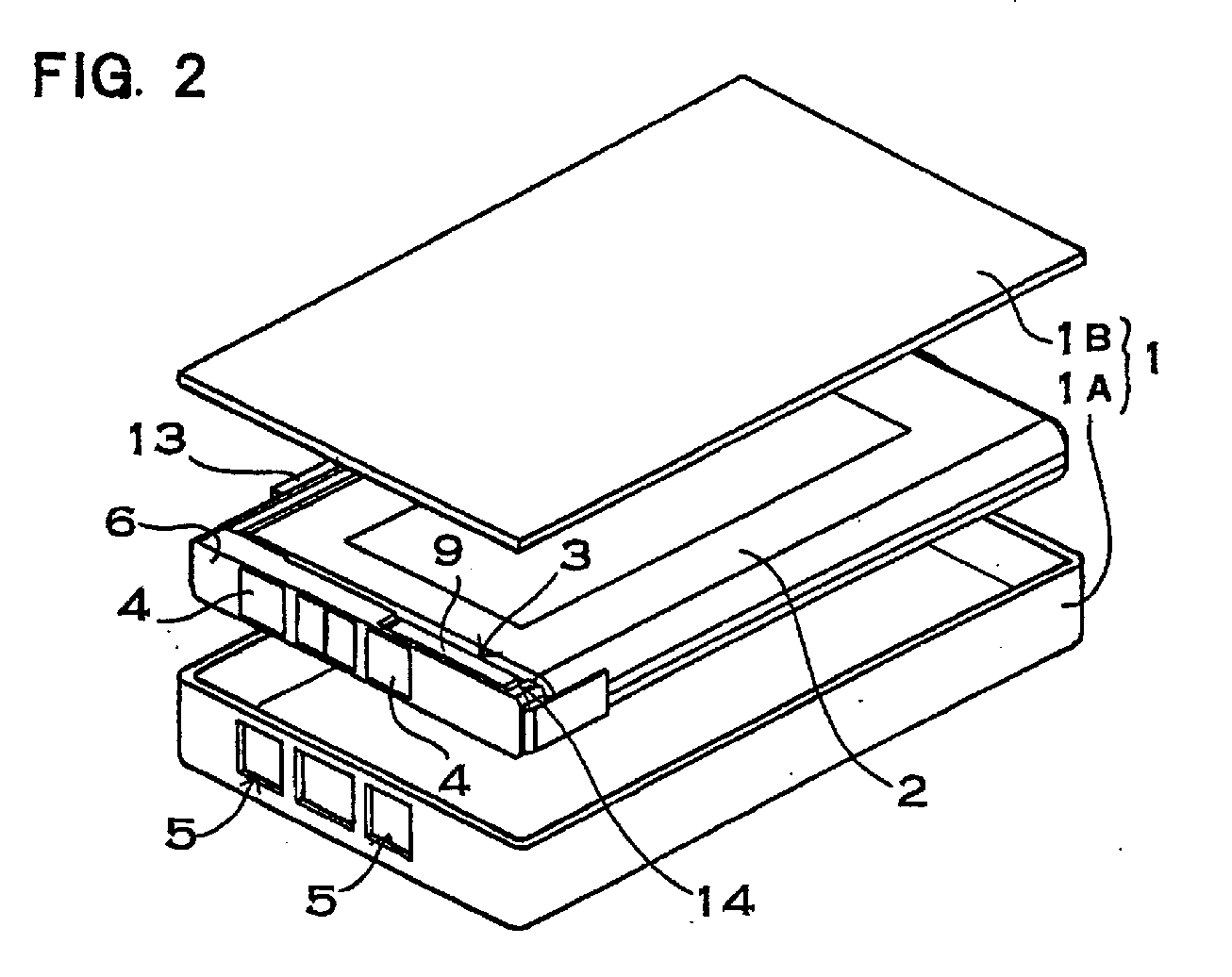
- Fig. 2 is an exploded oblique view of an embodiment of the battery pack of the present invention.
- Fig. 3 is a circuit diagram of the protection circuit of an embodiment of the battery pack of the present invention.
- Fig. 4 is a front view of a one-package unit housed in an embodiment a battery pack of the present invention.
- Fig. 5 is a plan view of an insulating substrate of the one-package unit shown in Fig. 4.
- Fig. 6 is a cross-section view of an insulating substrate of the one-package unit shown in Fig. 4.
- Fig. 7 is a front view showing another embodiment of a one-package unit.
- Fig. 8 is a plan view of the one-package unit shown in Fig. 7.
- Fig. 9 is a plan view of an insulating substrate of the one-package unit shown in Fig. 7.
- Fig. 10 is an exploded oblique view of the rechargeable cell and insulating holder of the battery pack shown in Fig. 2.
- Fig. 11 is an exploded oblique view of another embodiment of the battery pack of the present invention.
- Fig. 12 is an oblique view showing the assembled appearance of the battery pack shown in Fig. 11.
- Fig. 13 is an exploded oblique view of another embodiment of the battery pack of the present invention.
- Fig. 14 is an oblique view showing the assembled appearance of the battery pack shown in Fig. 13.
- Fig. 15 is an exploded oblique view of another embodiment of the battery pack, of the present invention.
- the case 1 is made up of a lower case 1A and an upper case 1B, which are formed pieces of heat-pliable plastic.
- the battery pack of the present invention does not necessarily require the case to be formed plastic, and for example, the case may also be configured from heat-shrink film.
- the lower case 1A has a box shape and houses the battery 2 and the protection circuit 3.
- the lower case 1A also has electrode windows 5 for exposing electrode terminals 4 outside the case. Electrode terminals 4 fixed to an insulating holder 6 are disposed inside the electrode windows 5, and the electrode terminals 4 are exposed outside the case.
- the ultra-sonic weld attached case 1 allows strong connection of case pieces without using connecting materials, and fixes the case 1 together in a manner that won't separate at the opening. This achieves the feature of a high quality battery pack that can be inexpensively produced in quantity.
- the case may also be assembled using a bonded or pressure fitted configuration.
- the case may also be a heat-shrink film structure encasing a connection of rechargeable cell, one-package unit, and insulating holder, rather than a formed plastic or metallic case.
- the battery pack of Fig. 2 houses within the case 1 a prismatic lithium ion rechargeable cell as the rechargeable cell 2.
- the battery pack of the present invention does not restrict the rechargeable cell to a lithium ion rechargeable cell.
- the rechargeable cell may be a rechargeable cell type presently in use, such as a nickel cadmium battery or a nickel hydrogen battery, or it may also be a new type of rechargeable cell yet to be developed. Further, the rechargeable cell does not necessarily have to be a prismatic battery.
- the rechargeable cell may also be a battery shape such as a cylindrical battery or coin battery.
- the protection circuit 3 is provided with switching devices connected in series with the rechargeable cell 2 to control current flow through the battery, and a control circuit to detect battery voltage or current or both and to control the switching devices.
- a circuit diagram of the protection circuit 3 is shown in Fig. 3 and a front view is shown in Fig. 4.
- the protection circuit 3 of these figures is provided with FETs, which are the switching devices 7, and a control circuit 8 to control those FETs. Instead of FETs, devices such as bipolar transistors may also be used as the switching devices.
- the switching devices 7 of the figures are an FET to control the charging state of the battery and an FET to control the discharging state connected in series.
- the gates of the FETs are connected to the control circuit 8, and signals output from the control circuit 8 control the FETs on and off.
- the protection circuit 8 puts both FETs in the on-state. If conditions become abnormal during battery charging, the FET controlling battery charging is turned off and charging current is cut-off. Likewise, if conditions become abnormal during battery discharge, the FET controlling battery discharge is turned off and discharge current is cut-off.
- the control circuit 8 detects battery voltage and current flowing through the battery, and controls the switching devices 7. If battery voltage exceeds a preset maximum voltage during charging, the control circuit 8 outputs a signal to turn off the FET controlling charging to prevent battery over-charging. Likewise, to prevent battery over-discharge, the control circuit 8 outputs a signal to turn off the FET controlling discharge if battery voltage drops below a preset minimum voltage. In addition, if the battery pack output side is short circuited and excessive current flows through the battery, or if by mistake a high charging voltage is applied to the battery pack and excessive current flows, the control circuit 8 detects the excessive current and outputs a signal to turn off the switching devices 7.
- the protection circuit 3 of Fig. 3 is made up of a pair of FETs, which are the switching devices 7, a control circuit 8, resistors, and capacitors. As shown in Fig. 4, electronic components such as these which make up the protection circuit 3 are molded into a single package with insulating material to make a one-package unit 9.
- the insulating material is epoxy resin. Since the epoxy resin for molding the protection circuit 3 can harden at room temperature by mixing two liquids without applying heat, the one-package unit 9 can be efficiently produced in quantity. In the hardened state, the epoxy resin is sufficiently strong. Further, since epoxy resin has excellent insulating and moisture resistance properties, the protection circuit 3 can be molded in an ideal manner. However, instead of epoxy resin, materials such as urethane resin or silicone resin can also be used as the insulating material for molding the protection circuit.
- the one-package unit 9 shown in Fig. 4 contains the protection circuit 3 within a two layer laminated package of insulating material.
- an insulating surface layer 98 is laminated without gaps to tightly adhere to the upper surface of a bottom layer insulating substrate 9A.
- the FETs, control circuit integrated circuit (IC), resistors, and capacitors to realize the protection circuit are fixed to the insulating substrate 9A.
- lead material 10 is connected to the insulating substrate 9A.
- the internal structure of the insulating substrate 9A is shown in the cross-section view of Fig. 6.
- electronic parts to implement the protection circuit including FETs, the control circuit IC, resistors and capacitors are mounted on the surface of substrate material such as glass epoxy resin or ceramic. That surface is then covered with insulating resin 21 to encase the electronic parts in the insulating resin 21.
- the upper surface of the insulating substrate 9A is provided with surface electrodes 22.
- Lead material 10 is connected to surface electrodes 22 on the insulating substrate 9A, and an insulating surface layer 9B is laminated to the upper surface of the insulating substrate 9A without creating gaps.
- lead material 10 can be connected to the insulating substrate 9A, and the insulating substrate 9A can be inserted in a plastic mold to fix the unit.
- the one-package unit 9 has the protection circuit 3 molded in a manner covering it above and below with insulating material, and embedding and fixing on end of the lead material 10 within the package.
- the insulating substrate 9A and the insulating surface layer 9B of the one-package unit 9 may be the same insulating material or different insulating material.
- the one-package unit 9 shown in Fig. 4 is also provided with a test-point hole 11 in its insulating surface layer 9B.
- the test-point hole 11 is opened at a position allowing the test-point 12 on the protection circuit 3 attached to the upper surface of the insulating substrate 9A to be contacted.
- a connecting pin is inserted into the test-point hole 11 to contact the test-point 12.
- the test-point hole 11 is sealed closed by a removable seal or filler material.
- the one-package unit can also be connected to a printed circuit board 719, and lead material 710 can be connected.
- Fig. 9 shows a bottom view of a one-package unit 79 for mounting on a printed circuit board 719.
- the one-package unit 79 shown in Fig. 9 has an overall rectangular shape and has surface electrodes disposed in the four comers of the bottom surface. The corner region surface electrodes may be disposed on two sides, as shown in Fig. 9, or they may be disposed on one side (not illustrated).
- This type of one-package unit 79 has the feature that proper connection of the surface electrodes to the printed circuit board 719 can be confirmed with the one-package unit 79 solder attached to the printed circuit board 719.
- cut-outs 723 are provided on the edge sides of the surface electrodes, and these cut-outs 723 allow even more precise confirmation of the connection between the surface electrodes and the printed circuit board 719.
- the battery pack has the characteristic that positive to negative battery short circuits can be effectively prevented.
- the B+ and B- surface electrodes are disposed in the upper corners, and the B- surface electrode and the V- surface electrode, which connects to a battery pack electrode terminal, are disposed on the left side comers.
- the B- surface electrode and the V- surface electrode can be connected with minimum wire length to reduce resistance between those electrodes.
- the one-package unit 79 shown in Fig. 9 has two test-point surface electrodes T1 and T2 disposed on the surface electrode side upper edge.
- Surface electrode T1 which is a test-point that connects to surface electrode B+ via a resistor, is disposed near the B+ surface electrode
- surface electrode T2 which is a test-point that connects to surface electrode V-via a resistor, is disposed near the B- surface electrode.
- This configuration of one-package unit 79 can reduce protection circuit malfunction when moisture has entered the battery pack. This is because short circuit current through surface electrodes B+, B-, and V- can be prevented via the test-point surface electrodes T1 and T2.
- the one-package unit 79 is solder attached to the surface of the printed circuit board 719.
- the one-package unit 79 is re-flow soldered for connection to the printed circuit board 719.
- Conducting film 724 is fixed to one side of the printed circuit board 719.
- Surface electrodes of the one-package unit 79 are connected to the printed circuit board 719 conducting film 724, and lead material 710 is also solder connected to the conducting film 724.
- the printed circuit board 719 structure with a one-package unit 79 and lead material 710 connected has the characteristic that lead material 710 can be joined to the one-package unit 79 with simple equipment.
- the one-package unit 9 housing the protection circuit 3 is disposed within the case of the battery pack by means of the insulating holder 6.
- the one-package unit 9 is disposed inside the case via the insulating holder 6 in the configuration shown in Fig. 4 with embedded lead material 10, or in the configuration shown in Fig. 7 with one-package unit 79 and lead material 710 attachment to the printed circuit board 719.
- the insulating holder 6 is a formed plastic piece provided with space 14 on its inside surface for holding a one-package unit 9 with no printed circuit board, or for holding a one-package unit attached to a printed circuit board. Electrode terminals 4 are embedded in the surface of the insulating holder 6.
- the one-package unit holding space 14 is established on the side facing the rechargeable cell 2.
- the holding space 14 opening is made to a size which retains the one-package unit 9 with almost no gaps.
- the one-package unit 9 and holding space 14 are made in a snap-together or pressure-fit configuration, or the printed circuit board with a one-package unit attached and the holding space 14 are made in a snap-together configuration.
- the battery pack shown in Fig. 2 has a rechargeable cell 2, which is a thin outline battery, contained in the case 1.
- the insulating holder 6 is disposed at one end of the rechargeable cell 2, and the one-package unit 9 is disposed between the insulating holder 6 and the rechargeable cell 2.
- the insulating holder 6 has a width approximately equal to the width of the rechargeable cell 2.
- the insulating holder 6 has electrode terminals 4 fixed to its front side and is provided with holding space 14 on its inside surface to contain the one-package unit with a configuration shown in Fig. 4 or Fig. 7.
- the insulating holder 6 is provided with side walls on both sides of its inside surface formed as a single piece with the insulating holder 6. One part of these side walls has cut-outs which establish the holding space 14 for housing the one-package unit 9.
- the battery pack of the present invention may also be configured with the holding space for housing the one-package unit established inside the side walls provided on the insulating holder.
- the printed circuit board to which the one-package unit is attached closes off the holding space.
- the structure can be such that the one-package unit is inserted inside the holding space, and the printed circuit board closes the holding space opening.
- the insulating holder 6 shown in the figures utilizes space adjacent to the projecting rechargeable cell 2 electrode as the holding space 14, and the one-package unit 9 is contained in that space.
- the one-package unit 9 contained here has lead material 10, which project in the lengthwise direction from the ends of the rectangular shaped one-package unit 9, and connect to projecting rechargeable cell 2 electrodes.
- the rectangular shaped one-package unit 9 resides in the insulating holder 6 holding space 14 parallel to the end of the long narrow rechargeable cell 2.
- This configuration allows lead material 10 connected to the one-package unit 9 to connect with projecting rechargeable cell 2 electrodes over a short distance.
- This configuration allows the one-package unit 9 or the printed circuit board with the one-package unit attached to be reliably retained in a fixed position.
- the battery pack since space adjacent to the projecting rechargeable cell 2 electrode can be efficiently used to house the one-package unit 9, the battery pack has the feature that it can house the protection circuit 3 and its external size can be reduced.
- leads 1115, 1315 are disposed on the surface of the thin outline battery.
- the one-package unit 119, 139 is fixed to a printed circuit board 1119, 1319 and mounted in the insulating holder 116, 136.
- Leads 1115, 1315 connecting the rechargeable cell 112, 132 and the one-package unit 119, 139 are located on the laterally extending wide surface 112A, 132A of the rechargeable cell 112, 132, and are disposed along the edge of that surface.
- One end of a lead 1115,1315 is connected to the rechargeable cell 112, 132, and the other end is connected to the one-package unit 119, 139 or to the printed circuit board 1119, 1319.
- the lead 1115, 1315 is arranged in this position and retained within the case (not illustrated).
- This configuration of battery pack can house a lead 1115, 1315, and efficiently use the volume inside the case. This is because the laterally wide surface of a thin prismatic battery expands at the center when internal pressure becomes great. This creates a gap between the case and the rechargeable cell 112, 132, but a lead is disposed in this gap.
- the wide central portion of a rechargeable cell 112, 132 with high internal pressure expands, but the side edges do not expand.
- the lead 1115, 1315 is disposed along a side edge which does not expand, the case does not have to be made larger to accommodate the lead 1115, 1315.
- 114, 154 are the electrode terminals, 1110, 1510 is the lead material, and 1114, 1514 is the holding space.
- the three pieces of lead material 10 connected to the one-package unit 9 connect to the positive side battery electrode terminal 4, a PTC device 13, and the negative side battery electrode terminal 4.
- the PTC device 13 is connected in series with the battery and is disposed in contact with the battery surface. PTC device 13 resistance rapidly increases when battery temperature climbs to a prescribed temperature. Therefore, when battery temperature becomes abnormally high, current flow becomes negligible and is effectively cut-off. Since this battery pack is doubly protected by both a PCT device 13 and a protection circuit 3, reliability is made even greater.
- a battery pack with a doubly protected battery can also contain a fuse instead of a PCT device. Further, a battery pack can contain a fuse, a PCT device, and a protection circuit.
- the battery pack of the present invention does not necessarily have to contain a device such as a PCT or a fuse in addition to the protection circuit.
- a battery pack of this structure is assembled by the following steps.
- an electrode terminal holder 1525 may also be connected to the electrode terminals 154 of the insulating holder 156.
- the electrode terminal holder 1525 connected to the electrode terminals 154 is changed among various formats to correspond to the type of electrical equipment the battery pack will be housed in.
- a battery pack provided with an electrode terminal holder 1525 uses the same shaped insulating holder 156.
- the connected rechargeable cell 152, one-package unit 159, and insulating holder 156 are treated as a single unit and only the electrode terminal holder 1525 is made to adapt to a plurality of types of electrical equipment.
- this battery pack has the feature that it can be produced in quantity extremely efficiently.
- This battery pack is assembled by attaching the electrode terminal holder 1525 to the insulating holder 156 electrode terminals 154 and then installing them in a fixed position in the case, or by installing the rechargeable cell, one-package unit, and insulating holder in a fixed position in the case and then connecting the electrode terminal holder to the insulating holder electrode terminals.
- 1513 is the PCT device
- 1514 is the holding space
- 1515 is a lead.
- the rechargeable cell, one-package unit, and insulating holder are installed in a case, which is a formed plastic piece.
- a battery pack with a heat-shrink film case is assembled by covering the connected structure of one-package unit, insulating holder, and rechargeable cell with heat-shrink film.
- This battery pack can also be configured, for example, by providing electrode terminals on the insulating holder, or by extending leads outside without providing electrode terminals on the case, and joining the ends of the leads to connectors housing the electrode terminals.
Landscapes
- Engineering & Computer Science (AREA)
- Chemical & Material Sciences (AREA)
- Chemical Kinetics & Catalysis (AREA)
- Electrochemistry (AREA)
- General Chemical & Material Sciences (AREA)
- Manufacturing & Machinery (AREA)
- Microelectronics & Electronic Packaging (AREA)
- Power Engineering (AREA)
- Materials Engineering (AREA)
- Battery Mounting, Suspending (AREA)
- Connection Of Batteries Or Terminals (AREA)
- Secondary Cells (AREA)
Abstract
Description
Claims (25)
- A battery pack comprising:(1) a rechargeable cell;(2) a rechargeable cell protection circuit having;(a) a switching device [7] connected in series with the rechargeable cell [2] to control current flow through the battery;(b) a control circuit [8] to detect battery voltage or battery current or both, and control the switching device [7];(3) a case to house the protection circuit and the rechargeable cell;(4) a one-package unit [9], which is the protection circuit [3], provided with the switching device [7] and the control circuit [8], molded as a single package with insulating material; and(5) an insulating holder [6], which houses the one-package unit [9] in a holding space [14], and retains the one-package unit [9] in a specified position inside the case.
- A battery pack as recited in claim 1 wherein the rechargeable cell [2] is a prismatic lithium ion rechargeable cell.
- A battery pack as recited in claim 1 or 2 wherein the case [1] containing the rechargeable cell [2] the one-package unit [9], and the insulating holder [6] is a ultrasonic-weld attached plastic case.
- A battery pack as recited in any of the claims 1 to 3 wherein the one-package unit [9] is the protection circuit [3] molded in an epoxy resin.
- A battery pack as recited in claim 4 wherein the epoxy resin, which molds the protection circuit [3], is a resin which hardens at room temperature by mixing two liquids together without heating.
- A battery pack as recited in any of the claims 1 to 3 wherein the insulating material which molds the protection circuit is a silicone resin.
- A battery pack as recited in claim 1 or 2 wherein the one-package unit [9] is a laminated package of insulating material on both the upper and lower surfaces containing the protection circuit [3].
- A battery pack as recited in claim 7 wherein the one-package unit [9] is an insulating substrate [9A] bottom layer laminated with an upper surface insulating layer [9B] tightly sealing the unit without gaps.
- A battery pack as recited in claim 8 wherein FETs, a control circuit IC, resistors, and capacitors, which implement the protection circuit are mounted on the bottom layer insulating substrate [9A].
- A battery pack as recited in claim 8 wherein lead material is connected to the bottom layer insulating substrate [9A].
- A battery pack as recited in claim 9 wherein the bottom layer insulating substrate is a glass epoxy resin and an insulating resin [21] covers its surface.
- A battery pack as recited in claim 9 wherein the bottom layer insulating substrate is a ceramic material and an insulating resin [21] covers its surface.
- A battery pack as recited in claim 8 wherein the surface insulating layer is formed of plastic, and the insulating substrate [9A] is attached during plastic surface insulating layer formation by insertion into the plastic.
- A battery pack as recited in claim 8 wherein insulating substrate [9A] and the surface insulating layer [9B] of the one-package unit are the same insulating material.
- A battery pack as recited in claim 8 wherein insulating substrate [9A] and the surface insulating layer [9B] of the one-package unit are different insulating materials.
- A battery pack as recited in any of the claims 8 to 15 wherein a test-point hole is provided in the surface insulating layer [9B] of the one-package unit.
- A battery pack as recited in claim 16 wherein the test-point hole is opened at a location allowing contact with a test-point of the protection circuit [3] mounted on the upper surface of the insulating substrate [9A].
- A battery pack as recited in claim 16 wherein a removable seal or filler material closes off the test-point hole.
- A battery pack as recited in claim 16 wherein the one-package unit has two surface electrodes which are test-points disposed on the surface electrode side, a test-point surface electrode which connects to the B+ surface electrode via a resistor is disposed near the B+ surface electrode, and a test-point surface electrode which connects to the V- surface electrode via a resistor is disposed near the B- surface electrode.
- A battery pack as recited in any of the claims 1 to 19 wherein the insulating holder [6] is provided next to the rechargeable cell [2], the insulating holder [6] has the holding space [14] opening on the side facing the rechargeable cell [2], the one-package unit [9] is disposed in this holding space [14], and the insulating holder [6] is disposed at the end of the rechargeable cell [2].
- A battery pack as recited in any of the claims 1 to 19 wherein the one-package unit [9] is mounted on a printed circuit board [19], lead material [10] is joined to the printed circuit board [19], and the one-package unit [9] and the printed circuit board [19] are attached to the insulating holder [6].
- A battery pack as recited in any of the claims 1 to 21 wherein the one-package unit is rectangular shaped and has surface electrodes [B+] and [B-] disposed in the corner regions of its bottom surface.
- A battery pack as recited in claim 8 wherein surface electrodes [B+] and [B-], which connect to the rechargeable cell [2] positive and negative sides, are disposed at the ends of opposing sides of the one-package unit [9].
- A battery pack as recited in any of the claims 1 to 22 wherein the rechargeable cell [2] is a thin outline battery, and a lead to connect the one-package unit [9] to the rechargeable cell [2] is disposed along the side edge of the wide surface of thin outline rechargeable cell [2].
- A battery pack as recited in any of the claims 1 to 23 wherein the rechargeable cell [2] is a thin outline battery, the one-package unit is rectangular shaped, lead material [10] is joined to the one-package unit [9] in a fashion protruding lengthwise from the ends of the rectangular shaped one-package unit [9], lead material [10] extending from the ends of the one-package unit [9] connects with projecting rechargeable cell [2] electrodes, and the rectangular shaped one-package unit [9] is disposed in the holding space [14] of the insulating holder [6] in a manner orienting the one-package unit [9] parallel to the end of the long narrow rechargeable cell [2].
Applications Claiming Priority (4)
| Application Number | Priority Date | Filing Date | Title |
|---|---|---|---|
| JP4981899 | 1999-02-26 | ||
| JP4981899 | 1999-02-26 | ||
| JP09162499A JP3454748B2 (en) | 1999-02-26 | 1999-03-31 | Battery pack |
| JP9162499 | 1999-03-31 |
Publications (3)
| Publication Number | Publication Date |
|---|---|
| EP1032108A2 true EP1032108A2 (en) | 2000-08-30 |
| EP1032108A3 EP1032108A3 (en) | 2005-04-13 |
| EP1032108B1 EP1032108B1 (en) | 2008-09-10 |
Family
ID=26390273
Family Applications (1)
| Application Number | Title | Priority Date | Filing Date |
|---|---|---|---|
| EP00103902A Expired - Lifetime EP1032108B1 (en) | 1999-02-26 | 2000-02-24 | Battery pack |
Country Status (7)
| Country | Link |
|---|---|
| US (1) | US6492058B1 (en) |
| EP (1) | EP1032108B1 (en) |
| JP (1) | JP3454748B2 (en) |
| KR (1) | KR100535739B1 (en) |
| DE (1) | DE60040185D1 (en) |
| HU (1) | HU227186B1 (en) |
| TW (1) | TW437116B (en) |
Cited By (10)
| Publication number | Priority date | Publication date | Assignee | Title |
|---|---|---|---|---|
| EP1309020A3 (en) * | 2001-11-01 | 2004-01-02 | Nokia Corporation | Battery pack for electronic device |
| WO2005001986A3 (en) * | 2003-06-13 | 2005-03-17 | Gillette Co | Fuel cartridge interconnect for portable fuel cells |
| EP1626450A1 (en) * | 2004-03-03 | 2006-02-15 | LG Electronics Inc. | Battery coupling device of mobile terminal |
| EP1630889A1 (en) * | 2004-06-30 | 2006-03-01 | Tyco Electronics Nederland B.V. | Battery cap for a battery cell of a mobile electronic device |
| EP1487032A4 (en) * | 2002-02-13 | 2008-10-08 | Matsushita Electric Industrial Co Ltd | METHOD FOR MANUFACTURING A BATTERY PACK |
| EP1692734A4 (en) * | 2003-12-08 | 2008-10-29 | Lg Chemical Ltd | PROTECTIVE CIRCUIT MODULE (PCM) MOLD AND ACCUMULATOR HAVING THE SAME |
| US7482091B2 (en) | 2003-07-09 | 2009-01-27 | The Gillette Company | Fuel cartridge interconnect for portable fuel cells |
| US7642007B2 (en) * | 2001-06-29 | 2010-01-05 | Sanyo Electric Co., Ltd. | Battery pack and its method of manufacture |
| CN101958433A (en) * | 2009-07-16 | 2011-01-26 | 哈米尔顿森德斯特兰德公司 | Centre tapped battery pack and use the electric power distribution system of this battery pack |
| EP2378588A3 (en) * | 2010-04-07 | 2013-06-05 | Sony Corporation | Battery pack and method for making same |
Families Citing this family (79)
| Publication number | Priority date | Publication date | Assignee | Title |
|---|---|---|---|---|
| JP4904614B2 (en) * | 2000-06-22 | 2012-03-28 | パナソニック株式会社 | Battery pack and manufacturing method thereof |
| US7103694B2 (en) | 2000-09-08 | 2006-09-05 | Hewlett-Packard Development Company, L.P. | Method and apparatus implementing a tuned stub SCSI topology |
| US7007184B2 (en) * | 2000-09-08 | 2006-02-28 | Hewlett-Packard Development Company, L.P. | DIMM connector accomodating sideband signals for battery status and/or control |
| US20020080541A1 (en) * | 2000-09-08 | 2002-06-27 | Bunker M. Scott | Removable battery pack for a cache card |
| JP3737389B2 (en) | 2001-06-19 | 2006-01-18 | 京セラ株式会社 | battery |
| JP5036107B2 (en) * | 2001-06-28 | 2012-09-26 | 三洋電機株式会社 | battery |
| JP5128739B2 (en) * | 2001-09-03 | 2013-01-23 | 三洋電機株式会社 | Battery pack manufacturing method |
| US7130198B2 (en) * | 2001-12-06 | 2006-10-31 | Rohm Co., Ltd. | Resin-packaged protection circuit module for rechargeable batteries and method of making the same |
| US7318978B2 (en) * | 2001-12-07 | 2008-01-15 | Sony Corporation | Battery pack |
| KR100442656B1 (en) * | 2001-12-20 | 2004-08-02 | 텔슨전자 주식회사 | Method for manufacturing package type battery |
| JP2003223871A (en) * | 2002-01-29 | 2003-08-08 | Sanyo Electric Co Ltd | Battery and portable power supply using the same |
| JP3668195B2 (en) * | 2002-01-31 | 2005-07-06 | 三洋電機株式会社 | Pack battery manufacturing method |
| CN2525687Y (en) * | 2002-02-04 | 2002-12-11 | 深圳市比亚迪电子有限公司 | Lithium secondary battery with built-in protective circuit |
| CN100356612C (en) * | 2002-02-13 | 2007-12-19 | 松下电器产业株式会社 | Battery pack and manufacturing method thereof |
| JP4629952B2 (en) * | 2002-02-13 | 2011-02-09 | パナソニック株式会社 | Manufacturing method of secondary battery |
| KR100453898B1 (en) * | 2002-04-15 | 2004-10-20 | 삼성에스디아이 주식회사 | A battery pack for a portable electronic device |
| USD478866S1 (en) | 2002-07-04 | 2003-08-26 | Nintendo Co., Ltd. | Storage battery |
| JP3614158B2 (en) * | 2002-08-21 | 2005-01-26 | ソニー株式会社 | battery pack |
| KR100482409B1 (en) * | 2002-12-09 | 2005-04-14 | 넥스콘 테크놀러지 주식회사 | Protective device for lithium ion secondary battery |
| KR100502337B1 (en) * | 2002-12-26 | 2005-07-20 | 삼성에스디아이 주식회사 | Lithium secondary battery |
| KR100477752B1 (en) * | 2002-12-26 | 2005-03-21 | 삼성에스디아이 주식회사 | Protector and lithium secondary battery having the same |
| USD481995S1 (en) | 2003-01-23 | 2003-11-11 | Sony Corporation | Rechargeable battery |
| US7348762B2 (en) * | 2003-05-01 | 2008-03-25 | Sony Corporation | Battery pack and method for producing battery pack |
| CN2631052Y (en) * | 2003-06-13 | 2004-08-04 | 比亚迪股份有限公司 | Lithium ion cell |
| KR100515354B1 (en) | 2003-06-19 | 2005-09-15 | 삼성에스디아이 주식회사 | Secondary battery |
| JP4586341B2 (en) * | 2003-08-13 | 2010-11-24 | ソニー株式会社 | Square battery |
| USD492649S1 (en) | 2003-08-27 | 2004-07-06 | Pb 299 | Battery |
| JP5013666B2 (en) * | 2003-10-17 | 2012-08-29 | ソニー株式会社 | Battery pack using exterior film and battery pack manufacturing method |
| US8313856B2 (en) | 2003-10-17 | 2012-11-20 | Sony Corporation | Structure of thin battery covered by outer packaging film, battery pack, and method for manufacturing battery pack |
| JP3922281B2 (en) * | 2003-11-14 | 2007-05-30 | ソニー株式会社 | Battery pack and battery pack manufacturing method |
| KR100462465B1 (en) * | 2003-11-20 | 2004-12-23 | 정천수 | A charging battery case having uni-jack, and a jack plug for the case |
| KR100556101B1 (en) * | 2003-12-16 | 2006-03-03 | 주식회사 엘지화학 | Secondary battery module |
| KR100585760B1 (en) * | 2004-02-28 | 2006-06-07 | 엘지전자 주식회사 | Molding part reinforcement of battery |
| USD503923S1 (en) | 2004-03-24 | 2005-04-12 | Jumpit As | Battery |
| DE602005004061T2 (en) | 2004-04-27 | 2008-12-11 | Matsushita Electric Industrial Co., Ltd., Kadoma | fuel cell unit |
| US7092746B2 (en) | 2004-06-02 | 2006-08-15 | Research In Motion Limited | Slim line battery pack |
| CN100514712C (en) * | 2004-07-26 | 2009-07-15 | 株式会社Lg化学 | Connection structure for electrical connection of PCM and battery cell and secondary battery including the same |
| KR100601509B1 (en) | 2004-09-22 | 2006-07-19 | 삼성에스디아이 주식회사 | Case of battery pack |
| CN2772044Y (en) * | 2004-11-18 | 2006-04-12 | 比亚迪股份有限公司 | Lithium ion secondary cell |
| JP3973166B2 (en) * | 2004-11-19 | 2007-09-12 | 日立マクセル株式会社 | Battery pack |
| US20060127752A1 (en) * | 2004-12-09 | 2006-06-15 | Trw Automotive U.S. Llc | Battery with printed circuit |
| KR100877816B1 (en) * | 2005-01-21 | 2009-01-12 | 주식회사 엘지화학 | Battery pack with improved safety |
| KR100713630B1 (en) | 2005-03-21 | 2007-05-02 | 주식회사 파워로직스 | Battery Protection Circuit Board with Lead Type Static Poly Switch Surface Mounted and Fabrication Method |
| KR100686815B1 (en) * | 2005-04-26 | 2007-02-26 | 삼성에스디아이 주식회사 | Polymer battery packs and manufacturing methods thereof |
| USD517982S1 (en) | 2005-07-19 | 2006-03-28 | Compact Power Systems, Inc. | Portable battery |
| JP4822776B2 (en) * | 2005-09-02 | 2011-11-24 | 三洋電機株式会社 | Battery pack |
| JP4902156B2 (en) * | 2005-09-02 | 2012-03-21 | 三洋電機株式会社 | Battery pack |
| KR100719720B1 (en) * | 2005-09-22 | 2007-05-17 | 삼성에스디아이 주식회사 | Pack battery |
| KR100879894B1 (en) * | 2005-10-21 | 2009-01-21 | 주식회사 엘지화학 | Battery pack with no welding |
| KR100878703B1 (en) * | 2005-11-28 | 2009-01-14 | 주식회사 엘지화학 | Small battery pack with PCM in side sealing part |
| KR100839785B1 (en) * | 2005-12-29 | 2008-06-19 | 삼성에스디아이 주식회사 | Secondary Battery and Formation Method |
| KR100889242B1 (en) * | 2006-05-15 | 2009-03-17 | 주식회사 엘지화학 | WMS with waterproof function |
| US7768231B2 (en) * | 2006-09-18 | 2010-08-03 | Lg Chem, Ltd. | Battery pack |
| KR100685605B1 (en) * | 2006-10-20 | 2007-02-22 | 주식회사 이랜텍 | Battery pack |
| KR100685115B1 (en) * | 2006-10-20 | 2007-02-22 | 주식회사 이랜텍 | Battery pack |
| KR100770106B1 (en) | 2006-10-24 | 2007-10-24 | 삼성에스디아이 주식회사 | Lithium secondary battery |
| KR100865400B1 (en) * | 2007-05-21 | 2008-10-24 | 삼성에스디아이 주식회사 | Lithium polymer battery |
| US7723961B2 (en) * | 2007-08-07 | 2010-05-25 | Honeywell International Inc. | MEMS based battery monitoring technical field |
| KR100928119B1 (en) | 2007-10-30 | 2009-11-24 | 삼성에스디아이 주식회사 | Printed Circuit Board and Secondary Battery Using the Same |
| JP5345633B2 (en) | 2007-11-29 | 2013-11-20 | エルジー・ケム・リミテッド | Secondary battery pack with precise structure |
| JPWO2009125544A1 (en) | 2008-04-11 | 2011-07-28 | 川崎重工業株式会社 | Sealed prismatic battery and battery module using the same |
| KR101065952B1 (en) * | 2008-12-02 | 2011-09-19 | 삼성에스디아이 주식회사 | Card type battery |
| CN102986054B (en) * | 2010-07-16 | 2016-03-16 | 株式会社Lg化学 | Rotary jig for battery cell and method for welding battery cell using same |
| KR101319523B1 (en) | 2011-12-19 | 2013-11-06 | 지에스나노텍 주식회사 | Thin film cells module and thin film cells package and apparatus for packaging thin film cells and method for manufacturing thin film cells package |
| DE102012202433A1 (en) * | 2012-02-17 | 2013-08-22 | Robert Bosch Gmbh | Sensor device for a battery cell of an electrical energy storage, battery cell, method for producing the same and method for monitoring the same |
| JP5735170B2 (en) * | 2012-03-15 | 2015-06-17 | 株式会社東芝 | Lithium ion secondary battery |
| KR101401477B1 (en) * | 2012-08-02 | 2014-05-29 | 주식회사 엘지화학 | Connecting element for secondary battery, Battery module and Battery pack comprising the same |
| KR101392975B1 (en) * | 2012-11-12 | 2014-05-08 | 재단법인대구경북과학기술원 | Non-stop battery changing system |
| US9385356B2 (en) * | 2014-04-30 | 2016-07-05 | Ford Global Technologies, Llc. | Terminal holder for electric vehicle battery assembly |
| US9819069B2 (en) * | 2015-02-11 | 2017-11-14 | Google Inc. | Multi-band antenna with a battery resonator |
| US9662997B2 (en) * | 2015-02-11 | 2017-05-30 | Ford Global Technologies, Llc | Method and apparatus for attaching a crushable carbon fiber reinforced polymer structure to the outer surface of a battery enclosure |
| CN106159356B (en) * | 2016-06-30 | 2019-07-26 | 联想(北京)有限公司 | A kind of battery and electronic equipment |
| JP6620943B2 (en) | 2016-10-25 | 2019-12-18 | トヨタ自動車株式会社 | Manufacturing method of laminated electrode body |
| US10950912B2 (en) | 2017-06-14 | 2021-03-16 | Milwaukee Electric Tool Corporation | Arrangements for inhibiting intrusion into battery pack electrical components |
| JP6965717B2 (en) * | 2017-12-13 | 2021-11-10 | トヨタ自動車株式会社 | Battery pack manufacturing method |
| CN111261804A (en) * | 2018-12-03 | 2020-06-09 | 丰能科技股份有限公司 | Method and structure of battery packaging |
| KR102416919B1 (en) | 2019-02-26 | 2022-07-04 | 주식회사 엘지에너지솔루션 | Battery module |
| WO2021102976A1 (en) * | 2019-11-29 | 2021-06-03 | 东莞新能德科技有限公司 | Battery |
| CN113904033B (en) | 2021-09-16 | 2024-07-30 | 宁德新能源科技有限公司 | Battery cell and electric equipment |
Family Cites Families (21)
| Publication number | Priority date | Publication date | Assignee | Title |
|---|---|---|---|---|
| US3387076A (en) * | 1964-08-14 | 1968-06-04 | Hitachi Ltd | Methods of molding plastic objects with inserts |
| US4009141A (en) * | 1972-07-07 | 1977-02-22 | General Electric Company | Electrical insulating compositions of epoxy resins, zirconium silicate and alumina |
| JPS54134774A (en) * | 1978-04-12 | 1979-10-19 | Toray Silicone Co Ltd | Silicon resin composition for foam molding |
| US4246148A (en) * | 1979-08-27 | 1981-01-20 | Celanese Corporation | Two component aqueous coating composition based on an epoxy-polyamine adduct and a polyepoxide |
| US5102753A (en) * | 1990-11-26 | 1992-04-07 | Gould Inc. | Constant current source power supply |
| JPH05308107A (en) * | 1991-07-01 | 1993-11-19 | Sumitomo Electric Ind Ltd | Semiconductor device and its manufacture |
| US5240435A (en) * | 1991-09-25 | 1993-08-31 | Progressive Systems, Inc. | Electrical safety device |
| US5703405A (en) * | 1993-03-15 | 1997-12-30 | Motorola, Inc. | Integrated circuit chip formed from processing two opposing surfaces of a wafer |
| FR2706083A1 (en) * | 1993-06-02 | 1994-12-09 | Texas Instruments France | Improvements relating to battery unit assemblies. |
| US5459388A (en) * | 1993-09-10 | 1995-10-17 | Compaq Computer Corp. | Battery pack with minimum hard wiring connection for portable computer |
| US5492586A (en) * | 1993-10-29 | 1996-02-20 | Martin Marietta Corporation | Method for fabricating encased molded multi-chip module substrate |
| SE511032C2 (en) * | 1994-06-22 | 1999-07-26 | Intra International Ab | Connection of control circuit for battery with theft protection |
| JP2979963B2 (en) | 1994-07-21 | 1999-11-22 | 日本電池株式会社 | Rechargeable battery |
| JPH08250827A (en) * | 1995-03-08 | 1996-09-27 | Shinko Electric Ind Co Ltd | Semiconductor device package, manufacturing method thereof, and semiconductor device |
| JP3244400B2 (en) * | 1995-06-05 | 2002-01-07 | 三洋電機株式会社 | Battery pack |
| US5626980A (en) * | 1995-08-28 | 1997-05-06 | Motorola, Inc. | Contact block in a battery pack having snap in features |
| JP3176542B2 (en) * | 1995-10-25 | 2001-06-18 | シャープ株式会社 | Semiconductor device and manufacturing method thereof |
| JP2804735B2 (en) * | 1995-11-13 | 1998-09-30 | 三洋電機株式会社 | Manufacturing method of battery pack |
| US5534366A (en) * | 1995-11-22 | 1996-07-09 | Motorola, Inc. | Modular battery pack |
| JP3531090B2 (en) * | 1996-11-07 | 2004-05-24 | 日立マクセル株式会社 | Battery pack |
| DE69833604T2 (en) * | 1997-11-05 | 2006-12-21 | Philips Consumer Communications France | Battery unit and portable battery-operated device with such a battery unit |
-
1999
- 1999-03-31 JP JP09162499A patent/JP3454748B2/en not_active Expired - Fee Related
- 1999-12-23 TW TW088122722A patent/TW437116B/en not_active IP Right Cessation
-
2000
- 2000-01-18 KR KR10-2000-0002232A patent/KR100535739B1/en not_active Expired - Fee Related
- 2000-02-24 US US09/512,334 patent/US6492058B1/en not_active Expired - Lifetime
- 2000-02-24 HU HU0000867A patent/HU227186B1/en not_active IP Right Cessation
- 2000-02-24 DE DE60040185T patent/DE60040185D1/en not_active Expired - Lifetime
- 2000-02-24 EP EP00103902A patent/EP1032108B1/en not_active Expired - Lifetime
Cited By (16)
| Publication number | Priority date | Publication date | Assignee | Title |
|---|---|---|---|---|
| US7642007B2 (en) * | 2001-06-29 | 2010-01-05 | Sanyo Electric Co., Ltd. | Battery pack and its method of manufacture |
| US6803144B2 (en) | 2001-11-01 | 2004-10-12 | Nokia Corporation | Battery pack for electronic device |
| EP1309020A3 (en) * | 2001-11-01 | 2004-01-02 | Nokia Corporation | Battery pack for electronic device |
| EP2299519A1 (en) * | 2001-11-01 | 2011-03-23 | Nokia Corporation | Battery pack for electronic device |
| US7927386B2 (en) | 2002-02-13 | 2011-04-19 | Matsushita Electric Industrial Co., Ltd. | Method for manufacturing a battery pack |
| EP1487032A4 (en) * | 2002-02-13 | 2008-10-08 | Matsushita Electric Industrial Co Ltd | METHOD FOR MANUFACTURING A BATTERY PACK |
| WO2005001986A3 (en) * | 2003-06-13 | 2005-03-17 | Gillette Co | Fuel cartridge interconnect for portable fuel cells |
| US7482091B2 (en) | 2003-07-09 | 2009-01-27 | The Gillette Company | Fuel cartridge interconnect for portable fuel cells |
| US7862926B2 (en) | 2003-07-09 | 2011-01-04 | The Gillette Company | Fuel cartridge interconnect for portable fuel cells |
| EP1692734A4 (en) * | 2003-12-08 | 2008-10-29 | Lg Chemical Ltd | PROTECTIVE CIRCUIT MODULE (PCM) MOLD AND ACCUMULATOR HAVING THE SAME |
| EP1626450A1 (en) * | 2004-03-03 | 2006-02-15 | LG Electronics Inc. | Battery coupling device of mobile terminal |
| EP1630889A1 (en) * | 2004-06-30 | 2006-03-01 | Tyco Electronics Nederland B.V. | Battery cap for a battery cell of a mobile electronic device |
| CN101958433A (en) * | 2009-07-16 | 2011-01-26 | 哈米尔顿森德斯特兰德公司 | Centre tapped battery pack and use the electric power distribution system of this battery pack |
| EP2276093A3 (en) * | 2009-07-16 | 2012-04-11 | Hamilton Sundstrand Corporation | Center-tapped battery and power distribution system for same |
| EP2378588A3 (en) * | 2010-04-07 | 2013-06-05 | Sony Corporation | Battery pack and method for making same |
| US10347874B2 (en) | 2010-04-07 | 2019-07-09 | Murata Manufacturing Co., Ltd. | Battery pack and method for making same |
Also Published As
| Publication number | Publication date |
|---|---|
| HUP0000867A3 (en) | 2005-05-30 |
| EP1032108A3 (en) | 2005-04-13 |
| KR100535739B1 (en) | 2005-12-09 |
| JP3454748B2 (en) | 2003-10-06 |
| EP1032108B1 (en) | 2008-09-10 |
| DE60040185D1 (en) | 2008-10-23 |
| US6492058B1 (en) | 2002-12-10 |
| HUP0000867A2 (en) | 2000-09-28 |
| TW437116B (en) | 2001-05-28 |
| HU227186B1 (en) | 2010-10-28 |
| JP2000311667A (en) | 2000-11-07 |
| KR20000057767A (en) | 2000-09-25 |
| HU0000867D0 (en) | 2000-04-28 |
Similar Documents
| Publication | Publication Date | Title |
|---|---|---|
| EP1032108B1 (en) | Battery pack | |
| EP1715534B1 (en) | Battery pack of improved structure | |
| JP5068544B2 (en) | Integrated type cap assembly including a protection circuit board and a secondary battery including the same | |
| KR100392340B1 (en) | Battery pack | |
| US6524732B1 (en) | Rechargeable battery with protective circuit | |
| EP1946394B1 (en) | No-welding type battery pack | |
| KR100870362B1 (en) | Protective Circuit Board for Secondary Battery and Secondary Battery Using the Same | |
| KR100929034B1 (en) | Battery packs and their manufacturing method | |
| EP2068419A2 (en) | Protection circuit module for a rechargeable battery | |
| EP2299519A1 (en) | Battery pack for electronic device | |
| US8962178B2 (en) | Battery pack | |
| JPWO2003096446A1 (en) | Thin battery and manufacturing method thereof | |
| JP2002124305A (en) | Battery pack | |
| CN112218444B (en) | Battery protection circuit package and manufacturing method thereof | |
| EP4376158A1 (en) | Battery pack | |
| JP2003022789A (en) | Battery and manufacturing method thereof | |
| US7733055B2 (en) | Battery pack and method of manufacturing the same | |
| JP3609662B2 (en) | Pack battery | |
| KR20070043513A (en) | Prefabricated protective circuit module and battery pack including same | |
| KR100659866B1 (en) | Lithium Secondary Battery and Manufacturing Method Thereof | |
| KR100889770B1 (en) | Ptc element and lithium ion secondary battery provided with the same | |
| KR20150121089A (en) | Protection element and electronic apparatus |
Legal Events
| Date | Code | Title | Description |
|---|---|---|---|
| PUAI | Public reference made under article 153(3) epc to a published international application that has entered the european phase |
Free format text: ORIGINAL CODE: 0009012 |
|
| AK | Designated contracting states |
Kind code of ref document: A2 Designated state(s): AT BE CH CY DE DK ES FI FR GB GR IE IT LI LU MC NL PT SE |
|
| AX | Request for extension of the european patent |
Free format text: AL;LT;LV;MK;RO;SI |
|
| RIC1 | Information provided on ipc code assigned before grant |
Ipc: 7H 02J 7/00 A Ipc: 7H 01M 10/48 B |
|
| PUAL | Search report despatched |
Free format text: ORIGINAL CODE: 0009013 |
|
| RIC1 | Information provided on ipc code assigned before grant |
Ipc: 7H 01L 21/56 B Ipc: 7H 01L 23/31 B Ipc: 7H 02J 7/00 A Ipc: 7H 01M 10/48 B |
|
| AK | Designated contracting states |
Kind code of ref document: A3 Designated state(s): AT BE CH CY DE DK ES FI FR GB GR IE IT LI LU MC NL PT SE |
|
| AX | Request for extension of the european patent |
Extension state: AL LT LV MK RO SI |
|
| 17P | Request for examination filed |
Effective date: 20050630 |
|
| AKX | Designation fees paid |
Designated state(s): DE FI FR GB IT |
|
| 17Q | First examination report despatched |
Effective date: 20050921 |
|
| GRAP | Despatch of communication of intention to grant a patent |
Free format text: ORIGINAL CODE: EPIDOSNIGR1 |
|
| RIN1 | Information on inventor provided before grant (corrected) |
Inventor name: TAMAI, MIKITAKA Inventor name: INOUE, YASUSHI Inventor name: KUBO, RYOSUKE Inventor name: ISHIHAMA, KEIJI Inventor name: WATANABE, ATSUSHI Inventor name: MATSUDA, TAKUYA Inventor name: YAMAGAMI, YASUHIRO |
|
| GRAS | Grant fee paid |
Free format text: ORIGINAL CODE: EPIDOSNIGR3 |
|
| GRAA | (expected) grant |
Free format text: ORIGINAL CODE: 0009210 |
|
| AK | Designated contracting states |
Kind code of ref document: B1 Designated state(s): DE FI FR GB IT |
|
| REG | Reference to a national code |
Ref country code: GB Ref legal event code: FG4D |
|
| REF | Corresponds to: |
Ref document number: 60040185 Country of ref document: DE Date of ref document: 20081023 Kind code of ref document: P |
|
| PG25 | Lapsed in a contracting state [announced via postgrant information from national office to epo] |
Ref country code: FI Free format text: LAPSE BECAUSE OF FAILURE TO SUBMIT A TRANSLATION OF THE DESCRIPTION OR TO PAY THE FEE WITHIN THE PRESCRIBED TIME-LIMIT Effective date: 20080910 |
|
| PLBE | No opposition filed within time limit |
Free format text: ORIGINAL CODE: 0009261 |
|
| STAA | Information on the status of an ep patent application or granted ep patent |
Free format text: STATUS: NO OPPOSITION FILED WITHIN TIME LIMIT |
|
| 26N | No opposition filed |
Effective date: 20090611 |
|
| PG25 | Lapsed in a contracting state [announced via postgrant information from national office to epo] |
Ref country code: IT Free format text: LAPSE BECAUSE OF FAILURE TO SUBMIT A TRANSLATION OF THE DESCRIPTION OR TO PAY THE FEE WITHIN THE PRESCRIBED TIME-LIMIT Effective date: 20080910 |
|
| PGFP | Annual fee paid to national office [announced via postgrant information from national office to epo] |
Ref country code: FR Payment date: 20120221 Year of fee payment: 13 |
|
| PGFP | Annual fee paid to national office [announced via postgrant information from national office to epo] |
Ref country code: DE Payment date: 20120222 Year of fee payment: 13 |
|
| PGFP | Annual fee paid to national office [announced via postgrant information from national office to epo] |
Ref country code: GB Payment date: 20120222 Year of fee payment: 13 |
|
| REG | Reference to a national code |
Ref country code: DE Ref legal event code: R082 Ref document number: 60040185 Country of ref document: DE Representative=s name: SCHUMACHER & WILLSAU PATENTANWALTSGESELLSCHAFT, DE |
|
| GBPC | Gb: european patent ceased through non-payment of renewal fee |
Effective date: 20130224 |
|
| REG | Reference to a national code |
Ref country code: FR Ref legal event code: ST Effective date: 20131031 |
|
| REG | Reference to a national code |
Ref country code: DE Ref legal event code: R119 Ref document number: 60040185 Country of ref document: DE Effective date: 20130903 |
|
| PG25 | Lapsed in a contracting state [announced via postgrant information from national office to epo] |
Ref country code: GB Free format text: LAPSE BECAUSE OF NON-PAYMENT OF DUE FEES Effective date: 20130224 Ref country code: DE Free format text: LAPSE BECAUSE OF NON-PAYMENT OF DUE FEES Effective date: 20130903 Ref country code: FR Free format text: LAPSE BECAUSE OF NON-PAYMENT OF DUE FEES Effective date: 20130228 |