EP1031759A1 - Switchable, hydraulically-damped support - Google Patents
Switchable, hydraulically-damped support Download PDFInfo
- Publication number
- EP1031759A1 EP1031759A1 EP00103831A EP00103831A EP1031759A1 EP 1031759 A1 EP1031759 A1 EP 1031759A1 EP 00103831 A EP00103831 A EP 00103831A EP 00103831 A EP00103831 A EP 00103831A EP 1031759 A1 EP1031759 A1 EP 1031759A1
- Authority
- EP
- European Patent Office
- Prior art keywords
- bearing
- core
- bearing according
- membrane
- valve
- Prior art date
- Legal status (The legal status is an assumption and is not a legal conclusion. Google has not performed a legal analysis and makes no representation as to the accuracy of the status listed.)
- Granted
Links
Images

Classifications
-
- F—MECHANICAL ENGINEERING; LIGHTING; HEATING; WEAPONS; BLASTING
- F16—ENGINEERING ELEMENTS AND UNITS; GENERAL MEASURES FOR PRODUCING AND MAINTAINING EFFECTIVE FUNCTIONING OF MACHINES OR INSTALLATIONS; THERMAL INSULATION IN GENERAL
- F16F—SPRINGS; SHOCK-ABSORBERS; MEANS FOR DAMPING VIBRATION
- F16F13/00—Units comprising springs of the non-fluid type as well as vibration-dampers, shock-absorbers, or fluid springs
- F16F13/04—Units comprising springs of the non-fluid type as well as vibration-dampers, shock-absorbers, or fluid springs comprising both a plastics spring and a damper, e.g. a friction damper
- F16F13/06—Units comprising springs of the non-fluid type as well as vibration-dampers, shock-absorbers, or fluid springs comprising both a plastics spring and a damper, e.g. a friction damper the damper being a fluid damper, e.g. the plastics spring not forming a part of the wall of the fluid chamber of the damper
- F16F13/08—Units comprising springs of the non-fluid type as well as vibration-dampers, shock-absorbers, or fluid springs comprising both a plastics spring and a damper, e.g. a friction damper the damper being a fluid damper, e.g. the plastics spring not forming a part of the wall of the fluid chamber of the damper the plastics spring forming at least a part of the wall of the fluid chamber of the damper
- F16F13/18—Units comprising springs of the non-fluid type as well as vibration-dampers, shock-absorbers, or fluid springs comprising both a plastics spring and a damper, e.g. a friction damper the damper being a fluid damper, e.g. the plastics spring not forming a part of the wall of the fluid chamber of the damper the plastics spring forming at least a part of the wall of the fluid chamber of the damper characterised by the location or the shape of the equilibration chamber, e.g. the equilibration chamber, surrounding the plastics spring or being annular
-
- F—MECHANICAL ENGINEERING; LIGHTING; HEATING; WEAPONS; BLASTING
- F16—ENGINEERING ELEMENTS AND UNITS; GENERAL MEASURES FOR PRODUCING AND MAINTAINING EFFECTIVE FUNCTIONING OF MACHINES OR INSTALLATIONS; THERMAL INSULATION IN GENERAL
- F16F—SPRINGS; SHOCK-ABSORBERS; MEANS FOR DAMPING VIBRATION
- F16F13/00—Units comprising springs of the non-fluid type as well as vibration-dampers, shock-absorbers, or fluid springs
- F16F13/04—Units comprising springs of the non-fluid type as well as vibration-dampers, shock-absorbers, or fluid springs comprising both a plastics spring and a damper, e.g. a friction damper
- F16F13/26—Units comprising springs of the non-fluid type as well as vibration-dampers, shock-absorbers, or fluid springs comprising both a plastics spring and a damper, e.g. a friction damper characterised by adjusting or regulating devices responsive to exterior conditions
- F16F13/264—Units comprising springs of the non-fluid type as well as vibration-dampers, shock-absorbers, or fluid springs comprising both a plastics spring and a damper, e.g. a friction damper characterised by adjusting or regulating devices responsive to exterior conditions comprising means for acting dynamically on the walls bounding a working chamber
Definitions
- the invention relates to a switchable, hydraulically damping bearing with the Features from the preamble of claim 1.
- Such a bearing is known from DE 42 38 752 C1.
- the air chamber over the Check valve pumped empty to increase the spring stiffness of the bearing increase.
- the venting of the Air chamber possible without outside help.
- the valve opened and thereby the air chamber with the atmosphere connected. The membrane then moves back to its original position.
- the invention has for its object a switchable, hydraulic to further develop damping bearings of the type mentioned at the beginning, that this with very small dimensions and low overall height if necessary has a high spring stiffness and high damping.
- the air chamber with the valve closed and Train movements of the bearing to increase the bearing rigidity with the Check valve inflowing air is inflatable.
- the air chamber with the valve closed and Train movements of the bearing to increase the bearing rigidity with the Check valve inflowing air is inflatable.
- the Support bearing comprises a core and a core plate, which with the suspension spring is adhesively connected, the core sheet with the core and is sealingly connected.
- the air chamber is preferred from the membrane, the core and the Core sheet limited.
- the membrane preferably extends transversely to Direction of the vibrations introduced and is in an axial direction Directionally extending flange of the core sheet sealed.
- the Membrane that is transverse to the direction of the vibrations introduced extends opposite diaphragms that are introduced towards the Vibrations extend, such as the membrane from the State of the art mentioned in the introduction, the advantage that it is immediate without redirecting the flow and resulting losses can be applied.
- An integration at the core requires practically none additional height, so that the bearing can be made compact.
- There is also a geometric separation from the nozzle-membrane system for coordinating the function is an advantage.
- the suspension spring and the membrane are preferably of the same material and integrally formed into one another. Both the suspension spring and the membrane is also preferred in one operation with the Core sheet vulcanized, which is inexpensive and easy Manufacturing is of particular advantage.
- the valve can be actuated electromagnetically. Different ones Actuations, such as a pneumatic or hydraulic Actuation is also conceivable, with the electromagnetic Actuation of the valve because of the exact switchability especially for the Suitable for use with engine mounts.
- the valve is preferably signal-conducting with the engine management system Internal combustion engine connected and connects the air chamber in the Idle of the internal combustion engine with the environment or is at Speeds outside the idle range locked.
- Internal combustion engine connected and connects the air chamber in the Idle of the internal combustion engine with the environment or is at Speeds outside the idle range locked.
- the bearing is preferably used as a motor bearing to support one Internal combustion engine for use. At idle the Internal combustion engine, the valve is open so that the pressure corresponds to atmospheric pressure within the air chamber. In this Operating condition, the spring stiffness of the bearing is comparatively low, to isolate or erase idle vibrations.
- the valve and the check valve preferably form a preassembled one Unit.
- the assembly of the unit on the warehouse is considerably simplified and minimizes the risk of assembly errors.
- the core can be essentially circular, the Unit is connected to the core.
- the unit is arranged in a central recess of the core and is screwed to the core.
- the flow-guiding connection between the air chamber and the atmosphere either via the valve or via the Check valve is made by a hollow cylindrical core screw or a hollow cylindrical stud.
- the core and / or the unit can have at least one stop buffer have, the membrane to limit extreme Deflection movements with pressure movements of the bearing on the Stop buffer can be created.
- the membrane to limit extreme Deflection movements with pressure movements of the bearing on the Stop buffer can be created.
- Large-amplitude, low-frequency Vibrations arise, for example, pressure peaks within the Chamber of Labor.
- Stop buffer may be provided. As a result, the bearing remains the same good performance characteristics over a long period of use.
- the membrane can be on the side facing the stop buffer Have surface profiling.
- the surface profiling can for example by an irregular profile in the form of stop knobs be formed to stop noise when touching the Avoid bumpers.
- the membrane can be a stop buffer with a static preload of the bearing touch with elastic pre-tension.
- At least the suspension spring can be on the outer circumference of one Thermal protection cap to be enclosed.
- the heat protection cap is preferred fixed to the support bearing and prevents immediate Heat radiation from a connected internal combustion engine the suspension spring made of an elastomeric material. Besides, is advantageous that also within the working and the compensation chamber damping fluid in front of an undesirably high Temperature exposure is protected, which is consistent in terms good usage properties is an advantage to be emphasized.
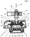
- the bearing is a switchable, formed hydraulically damping bearing and comprises a support bearing 1 and a support 2, which are supported on each other by the suspension spring 3.
- the Working 4 and the compensation chamber 5 are each with damping liquid 7 filled and in the direction 6 of the vibrations introduced arranged one behind the other.
- the Partition 8 is formed in two parts in this embodiment, wherein between the two parts 8.1, 8.2 of the partition 8 a Decoupling membrane made of elastomeric material for insulation high-frequency, small-amplitude vibrations is arranged.
- the Air chamber 11 is through the electromagnetically actuated valve 12 and the check valve 13 is connected to the environment 14 in a flow-conducting manner, the unit 18, consisting of the valve 12 and the Check valve 13 is screwed to the core 15, which has a recess 19, which is arranged centrally in Figure 1.
- the air chamber 11 is when the valve 12 is closed and the train moves Bearing to increase the bearing rigidity with the check valve 13th inflatable after flowing air.
- Warehouse does the following:
- the bearing shown arrives as a motor bearing to support one Internal combustion engine for use.
- the valve 12 At idle the Internal combustion engine, the valve 12 is open so that the pressure corresponds to the atmospheric pressure within the air chamber 11. In this Operating condition, the spring stiffness of the bearing is comparatively low, to isolate or erase idle vibrations.
- the core 15 has an annular shape Stop buffer 20 to which the membrane to limit extreme Deflection movements can be applied to pressure movements of the bearing.
- the heat protection cap 22 is fixedly connected to the support bearing 1 and covers the suspension spring 3 and the working chamber 4 in the axial direction.
- Figure 2 shows a second embodiment in which the air-guiding Recess 19 is arranged laterally. This enables the switching Unit 18 of switched valve 12 and check valve 13 more in to be arranged offset in the radial direction and the overall height to to reduce. Also helpful is the holder attached to the core 15 24, which depending on the space available in the vehicle either with the engine or the body is connected in the air duct to the air chamber 11 with to involve.
Abstract
Description
Die Erfindung betrifft ein schaltbares, hydraulisch dämpfendes Lager mit den Merkmalen aus dem Oberbegriff von Anspruch 1.The invention relates to a switchable, hydraulically damping bearing with the Features from the preamble of claim 1.
Ein solches Lager ist aus der DE 42 38 752 C1 bekannt. Durch die Zug- und Druckbewegungen des Lagers wird die Luftkammer über das Rückschlagventil leergepumpt, um die Federsteifigkeit des Lagers zu erhöhen. Durch die Verwendung des Rückschlagventils ist die Entlüftung der Luftkammer ohne Fremdhilfe möglich. Für die Belüftung der Luftkammer wird das Ventil geöffnet und dadurch die Luftkammer mit der Atmosphäre verbunden. Die Membran bewegt sich dann wieder in ihre Ausgangsposition.Such a bearing is known from DE 42 38 752 C1. By the train and Pressure movements of the bearing, the air chamber over the Check valve pumped empty to increase the spring stiffness of the bearing increase. By using the check valve, the venting of the Air chamber possible without outside help. For ventilation of the air chamber the valve opened and thereby the air chamber with the atmosphere connected. The membrane then moves back to its original position.
Der Erfindung liegt die Aufgabe zugrunde, ein schaltbares, hydraulisch dämpfendes Lager der eingangs genannten Art derart weiterzuentwickeln, daß dieses bei sehr kleinen Abmessungen und niedriger Bauhöhe bedarfsweise eine große Federsteifigkeit und eine hohe Dämpfung aufweist.The invention has for its object a switchable, hydraulic to further develop damping bearings of the type mentioned at the beginning, that this with very small dimensions and low overall height if necessary has a high spring stiffness and high damping.
Diese Aufgabe wird erfindungsgemäß mit den Merkmalen von Anspruch 1 gelöst. Auf vorteilhafte Ausgestaltungen nehmen die Unteransprüche bezug.This object is achieved with the features of claim 1 solved. The subclaims refer to advantageous configurations.
Im Rahmen der vorliegenden Erfindung ist es zur Lösung der Aufgabe vorgesehen, daß die Luftkammer bei geschlossenem Ventil und Zugbewegungen des Lagers zur Erhöhung der Lagersteifigkeit mit über das Rückschlagventil nachströmender Luft aufblähbar ist. Als Umgebung kann in Abhängigkeit vom jeweiligen Anwendungsfall die das Lager umgebende Atmosphäre betrachtet werden.In the context of the present invention, it is to solve the problem provided that the air chamber with the valve closed and Train movements of the bearing to increase the bearing rigidity with the Check valve inflowing air is inflatable. As an environment in Depending on the respective application, the one surrounding the warehouse Atmosphere.
Gemäß einer vorteilhaften Ausgestaltung kann es vorgesehen sein, daß das Traglager einen Kern und ein Kernblech umfaßt, das mit der Tragfeder haftend verbunden ist, wobei das Kernblech mit dem Kern formschlüssig und dichtend verbunden ist. Hierbei ist von Vorteil, daß sich das mehrteilig ausgebildete Traglager einfach an verschiedene Lagertypen anpassen läßt. Es besteht beispielsweise die Möglichkeit, unterschiedlich ausgebildete Kerne mit jeweils demselben Kernblech zu verbinden, wobei lediglich die Anschlußbereiche der Kerne übereinstimmend ausgebildet sind. Neben unterschiedlich gestalteten Kernen können diese auch aus voneinander abweichenden, an den jeweiligen Anwendungsfall angepaßten Werkstoffen bestehen.According to an advantageous embodiment, it can be provided that the Support bearing comprises a core and a core plate, which with the suspension spring is adhesively connected, the core sheet with the core and is sealingly connected. The advantage here is that there are several parts trained support bearings can easily adapt to different types of bearings. For example, there is the possibility of differently trained Connect cores to the same core sheet, only the Connection areas of the cores are designed to match. Next differently designed cores can also be made from each other deviating materials adapted to the respective application consist.
Die Luftkammer ist bevorzugt von der Membran, dem Kern und dem Kernblech begrenzt. Dabei erstreckt sich die Membran bevorzugt quer zur Richtung der eingeleiteten Schwingungen und ist mit einem sich in axialer Richtung erstreckenden Flansch des Kernblechs dichtend verbunden. Die Membran, die sich quer zur Richtung der eingeleiteten Schwingungen erstreckt, hat gegenüber Membranen, die sich in Richtung der eingeleiteten Schwingungen erstrecken, wie beispielsweise die Membran aus dem eingangs genannten Stand der Technik, den Vorteil, daß sie unmittelbar ohne Umlenkung der Strömung und dadurch auftretende Verluste beaufschlagt werden kann. Eine Integration im Kern benötigt praktisch keine zusätzliche Bauhöhe, so daß das Lager kompakt ausgeführt werden kann. Außerdem ist eine geometrische Trennung vom Düse-Membran-System für das Abstimmen der Funktion von Vorteil.The air chamber is preferred from the membrane, the core and the Core sheet limited. The membrane preferably extends transversely to Direction of the vibrations introduced and is in an axial direction Directionally extending flange of the core sheet sealed. The Membrane that is transverse to the direction of the vibrations introduced extends opposite diaphragms that are introduced towards the Vibrations extend, such as the membrane from the State of the art mentioned in the introduction, the advantage that it is immediate without redirecting the flow and resulting losses can be applied. An integration at the core requires practically none additional height, so that the bearing can be made compact. There is also a geometric separation from the nozzle-membrane system for coordinating the function is an advantage.
Die Tragfeder und die Membran sind bevorzugt materialeinheitlich und einstückig ineinander übergehend ausgebildet. Sowohl die Tragfeder als auch die Membran werden bevorzugt in einem Arbeitsgang mit dem Kernblech vulkanisiert, was im Hinblick auf eine kostengünstige und einfache Fertigung von hervorzuhebendem Vorteil ist. The suspension spring and the membrane are preferably of the same material and integrally formed into one another. Both the suspension spring and the membrane is also preferred in one operation with the Core sheet vulcanized, which is inexpensive and easy Manufacturing is of particular advantage.
Werden besonders weiche Membranen nötig, sind größere Durchmesser durch eine separate Ausführung der Membran sinnvoll.If particularly soft membranes are required, larger diameters are required sensible through a separate version of the membrane.
Das Ventil kann elektromagnetisch betätigbar sein. Davon abweichende Betätigungen, wie beispielsweise eine pneumatische oder hydraulische Betätigung sind ebenfalls denkbar, wobei sich die elektromagnetische Betätigung des Ventils wegen der exakten Schaltbarkeit besonders für die Verwendung mit Motorlagern eignet.The valve can be actuated electromagnetically. Different ones Actuations, such as a pneumatic or hydraulic Actuation is also conceivable, with the electromagnetic Actuation of the valve because of the exact switchability especially for the Suitable for use with engine mounts.
Das Ventil ist bevorzugt signalleitend mit dem Motormanagement einer Verbrennungskraftmaschine verbunden und verbindet die Luftkammer im Leerlauf der Verbrennungskraftmaschine mit der Umgebung oder ist bei Drehzahlen außerhalb des Leerlaufbereichs verschlossen. Zur Funktion des erfindungsgemäßen Lagers wird folgendes ausgeführt:The valve is preferably signal-conducting with the engine management system Internal combustion engine connected and connects the air chamber in the Idle of the internal combustion engine with the environment or is at Speeds outside the idle range locked. About the function of the The bearing according to the invention is carried out as follows:
Bevorzugt gelangt das Lager als Motorlager zur Abstützung einer Verbrennungskraftmaschine zur Anwendung. Im Leerlauf der Verbrennungskraftmaschine ist das Ventil geöffnet, so daß der Druck innerhalb der Luftkammer dem Atmosphärendruck entspricht. In diesem Betriebszustand ist die Federsteifigkeit des Lagers vergleichsweise gering, um Leerlaufvibrationen isolieren oder tilgen zu können.The bearing is preferably used as a motor bearing to support one Internal combustion engine for use. At idle the Internal combustion engine, the valve is open so that the pressure corresponds to atmospheric pressure within the air chamber. In this Operating condition, the spring stiffness of the bearing is comparatively low, to isolate or erase idle vibrations.
In Drehzahlbereichen oberhalb der Leerlaufdrehzahl, also im Fahrbetrieb, ist das Ventil demgegenüber geschlossen; die Luftkammer ist zur Umgebung hin hermetisch verschlossen. Während des Fahrbetriebs wird die Dämpfungsflüssigkeit zur Dämpfung großamplitudiger, niedrigfrequenter Schwingungen zwischen dem Arbeits- und dem Ausgleichskammer durch den Dämpfungskanal hin- und herverlagert. In diesem Betriebszustand verformt sich die die Luftkammer begrenzende Membran nur wenig, da die Luftkammer verschlossen und die darin befindlichen Luft während der Dämpfung der Schwingungen abwechselnd komprimiert und entspannt wird. Bei großen Schwingungsamplituden und daraus resultierenden großen Zugbewegungen des Lagers, entsteht ausfederungsbedingt ein Unterdruck innerhalb der Arbeitskammer. Dieser Unterdruck wölbt die Membran in Richtung der Arbeitskammer, so daß sich eine Volumenvergrößerung der Luftkammer ergibt. Da das Ventil geschlossen ist, besteht zum Ausgleich des Unterdrucks innerhalb der Luftkammer nur die Möglichkeit, daß Luft aus der Umgebung über das Rückschlagventil in die Luftkammer nachströmt. Bei einer Belastungsumkehr von einer Zugbewegung des Lagers in eine Druckbewegung schließt das Rückschlagventil selbsttätig. Die zuvor bei Zugbewegung in die Luftkammer gesaugte Luftmasse vermag daher nicht mehr aus der Luftkammer zu entweichen. Durch den erhöhten Druck innerhalb der Luftkammer stellt sich insgesamt eine größere Steifigkeit des Lagers ein, und die Dämpfung wird dadurch verbessert.In speed ranges above the idling speed, i.e. when driving in contrast, the valve is closed; the air chamber is to the environment hermetically sealed. During driving, the Damping fluid for damping large-amplitude, low-frequency Vibrations between the working and the compensation chamber moved the damping channel back and forth. In this operating state the membrane that delimits the air chamber deforms only slightly because the Air chamber closed and the air inside during the Damping the vibrations is alternately compressed and relaxed. With large vibration amplitudes and the resulting large ones Pulling movements of the bearing create a negative pressure due to the rebound inside the working chamber. This negative pressure bulges the membrane Direction of the working chamber, so that there is an increase in volume Air chamber results. Since the valve is closed, the Vacuum inside the air chamber only the possibility that air from the Flows into the air chamber via the check valve. At a load reversal from a pulling movement of the bearing into one Pressure movement closes the check valve automatically. The previously at Air mass sucked into the air chamber is therefore not able to pull to escape more from the air chamber. Due to the increased pressure there is a greater overall rigidity within the air chamber Bearing, and the damping is improved.
Bevorzugt bilden das Ventil und das Rückschlagventil eine vormontierbare Einheit. Die Montage der Einheit am Lager ist dadurch wesentlich vereinfacht und die Gefahr von Montagefehlern auf ein Minimum begrenzt.The valve and the check valve preferably form a preassembled one Unit. The assembly of the unit on the warehouse is considerably simplified and minimizes the risk of assembly errors.
Der Kern kann im wesentlichen kreisringförmig ausgebildet sein, wobei die Einheit mit dem Kern verbunden ist. Beispielsweise besteht die Möglichkeit, daß die Einheit in einer zentralen Ausnehmung des Kerns angeordnet und mit dem Kern verschraubt ist. Die strömungsleitende Verbindung zwischen der Luftkammer und der Atmosphäre entweder über das Ventil oder über das Rückschlagventil erfolgt dabei durch eine hohlzylinderförmige Kernschraube oder einen hohlzylinderförmigen Stehbolzen. Durch derartige Bauteile läßt sich nicht nur eine Befestigung der Einheit, bestehend aus Ventil und Rückschlagventil am Traglager erreichen, diese Teile bilden gleichzeitig eine Verbindungsleitung für die Luft zwischen der Umgebung und der Luftkammer.The core can be essentially circular, the Unit is connected to the core. For example, there is the possibility that the unit is arranged in a central recess of the core and is screwed to the core. The flow-guiding connection between the air chamber and the atmosphere either via the valve or via the Check valve is made by a hollow cylindrical core screw or a hollow cylindrical stud. Through such components not only a fastening of the unit consisting of valve and Reach the check valve on the support bearing, these parts also form one Connection line for the air between the environment and the Air chamber.
Der Kern und/oder die Einheit können zumindest einen Anschlagpuffer aufweisen, wobei die Membran zur Begrenzung extremer Auslenkbewegungen bei Druckbewegungen des Lagers an den Anschlagpuffer anlegbar ist. Bei großamplitudigen, tieffrequenten Schwingungen entstehen beispielsweise Druckspitzen innerhalb der Arbeitskammer. Um die im Vergleich zur Tragfeder wesentlich dünner ausgebildete Membran keinen unerwünscht hohen mechanischen Belastungen bei Druckbewegungen des Lagers auszusetzen, kann der Anschlagpuffer vorgesehen sein. Das Lager weist dadurch gleichbleibend gute Gebrauchseigenschaften während einer langen Gebrauchsdauer auf. The core and / or the unit can have at least one stop buffer have, the membrane to limit extreme Deflection movements with pressure movements of the bearing on the Stop buffer can be created. With large-amplitude, low-frequency Vibrations arise, for example, pressure peaks within the Chamber of Labor. To be much thinner compared to the suspension spring trained membrane no undesirably high mechanical Suspending loads during pressure movements of the bearing can Stop buffer may be provided. As a result, the bearing remains the same good performance characteristics over a long period of use.
Die Membran kann auf der dem Anschlagpuffer zugewandten Seite eine Oberflächenprofilierung aufweisen. Die Oberflächenprofilierung kann beispielsweise durch ein regelloses Profil in Form von Anschlagnoppen gebildet sein, um Anschlaggeräusche bei einer Berührung des Anschlagpuffers zu vermeiden.The membrane can be on the side facing the stop buffer Have surface profiling. The surface profiling can for example by an irregular profile in the form of stop knobs be formed to stop noise when touching the Avoid bumpers.
Die Membran kann einen Anschlagpuffer bei statischer Vorlast des Lagers unter elastischer Vorspannung anliegend berühren. Durch eine solche Ausgestaltung weist das erfindungsgemäße Lager weiter verbesserte dämpfende Eigenschaften auf.The membrane can be a stop buffer with a static preload of the bearing touch with elastic pre-tension. By such Embodiment has the bearing according to the invention further improved damping properties.
Zumindest die Tragfeder kann außenumfangsseitig von einer Wärmeschutzkappe umschlossen sein. Die Wärmeschutzkappe ist bevorzugt ortsfest am Traglager festgelegt und verhindert eine unmittelbare Wärmeabstrahlung einer angeschlossenen Verbrennungskraftmaschine auf die aus einem elastomeren Werkstoff bestehende Tragfeder. Außerdem ist von Vorteil, daß auch die innerhalb des Arbeits- und des Ausgleichskammers befindliche Dämpfungsflüssigkeit vor einer unerwünscht hohen Temperaturbeaufschlagung geschützt ist, was im Hinblick auf gleichbleibend gute Gebrauchseigenschaften von hervorzuhebenden Vorteil ist.At least the suspension spring can be on the outer circumference of one Thermal protection cap to be enclosed. The heat protection cap is preferred fixed to the support bearing and prevents immediate Heat radiation from a connected internal combustion engine the suspension spring made of an elastomeric material. Besides, is advantageous that also within the working and the compensation chamber damping fluid in front of an undesirably high Temperature exposure is protected, which is consistent in terms good usage properties is an advantage to be emphasized.
Zwei Ausführungsbeispiele des erfindungsgemäßen Lagers werden nachfolgend anhand der Zeichnungen näher erläutert.Two embodiments of the bearing according to the invention explained below with reference to the drawings.
In Figur 1 ist ein Ausführungsbeispiel eines erfindungsgemäßen Lagers in
schematischer Darstellung gezeigt. Das Lager ist als schaltbares,
hydraulisch dämpfendes Lager ausgebildet und umfaßt ein Traglager 1 und
ein Auflager 2, die durch die Tragfeder 3 aufeinander abgestützt sind. Die
Arbeits- 4 und die Ausgleichskammer 5 sind jeweils mit Dämpfungsflüssigkeit
7 gefüllt und in Richtung 6 der eingeleiteten Schwingungen
hintereinanderliegend angeordnet. Durch den Dämpfungskanal 9, der sich
innerhalb der Trennwand 8 befindet, sind die Arbeitskammer 4 und die
Ausgleichskammer 5 flüssigkeitsleitend miteinander verbunden. Die
Trennwand 8 ist in diesem Ausführungsbeispiel zweiteilig ausgebildet, wobei
zwischen den beiden Teilen 8.1, 8.2 der Trennwand 8 eine
Entkopplungsmembran aus elastomerem Werkstoff zur Isolierung
hochfrequenter, kleinamplitudiger Schwingungen angeordnet ist.1 shows an embodiment of a bearing according to the invention in
schematic representation shown. The bearing is a switchable,
formed hydraulically damping bearing and comprises a support bearing 1 and
a
In axialer Richtung, auf der dem Traglager 1 zugewandten Seite, ist die
Arbeitskammer 4 von einer Membran 10 aus elastomerem Werkstoff
begrenzt, die ebenfalls die Begrenzung für die Luftkammer 11 bildet. Die
Luftkammer 11 ist durch das elektromagnetisch betätigbare Ventil 12 und
das Rückschlagventil 13 strömungsleitend mit der Umgebung 14 verbunden,
wobei die Einheit 18, bestehend aus dem Ventil 12 und dem
Rückschlagventil 13 mit dem Kern 15 verschraubt ist, der eine Ausnehmung
19 aufweist, die in Figur 1 zentral angeordnet ist.In the axial direction, on the side facing the support bearing 1, the
Die Luftkammer 11 ist bei geschlossenem Ventil 12 und Zugbewegung des
Lagers zur Erhöhung der Lagersteifigkeit mit über das Rückschlagventil 13
nach strömender Luft aufblähbar. Zur Funktion des erfindungsgemäßen
Lagers wird folgendes ausgeführt:The
Das gezeigte Lager gelangt als Motorlager zur Abstützung einer
Verbrennungskraftmaschine zur Anwendung. Im Leerlauf der
Verbrennungskraftmaschine ist das Ventil 12 geöffnet, so daß der Druck
innerhalb der Luftkammer 11 dem Atmosphärendruck entspricht. In diesem
Betriebszustand ist die Federsteifigkeit des Lagers vergleichsweise gering,
um Leerlaufvibrationen isolieren oder tilgen zu können.The bearing shown arrives as a motor bearing to support one
Internal combustion engine for use. At idle the
Internal combustion engine, the
In Drehzahlbereichen oberhalb der Leerlaufdrehzahl, also im Fahrbetrieb, ist
das Ventil 12 demgegenüber geschlossen; die Luftkammer ist zur Umgebung
hin hermetisch verschlossen. Während des Fahrbetriebs wird die
Dämpfungsflüssigkeit 7 zur Dämpfung großamplitudiger, niedrigfrequenter
Schwingungen zwischen dem Arbeits- 4 und dem Ausgleichskammer 5 durch
den Dämpfungskanal 9 hin- und herverlagert. In diesem Betriebszustand
verformt sich die die Luftkammer 11 begrenzende Membran 10 nur wenig, da
die Luftkammer 11 verschlossen und die darin befindlichen Luft während der
Dämpfung der Schwingungen abwechselnd komprimiert und entspannt wird.
Bei Druckbewegungen des Lagers legt sich die Membrab 10 mit ihrer
Oberflächenprofilierung 21 an den Anschlagpuffer 20 an. Bei großen
Schwingungsamplituden und daraus resultierenden großen Zugbewegungen
des Lagers, entsteht ausfederungsbedingt ein Unterdruck innerhalb der
Arbeitskammer 4. Dieser Unterdruck wölbt die Membran 10 in Richtung der
Arbeitskammer 4, so daß sich eine Volumenvergrößerung der Luftkammer 11
ergibt. Da das Ventil 12 geschlossen ist, besteht zum Ausgleich des
Unterdrucks innerhalb der Luftkammer 11 nur die Möglichkeit, daß Luft aus
der Umgebung 14 über das Rückschlagventil 13 in die Luftkammer 11
nachströmt. Bei einer Belastungsumkehr von einer Zugbewegung des Lagers
in eine Druckbewegung schließt das Rückschlagventil 13 selbsttätig. Die
zuvor bei Zugbewegung in die Luftkammer 11 gesaugte Luftmasse vermag
daher nicht mehr aus der Luftkammer 11 zu entweichen. Durch den erhöhten
Druck innerhalb der Luftkammer 11 stellt sich insgesamt eine größere
Steifigkeit des Lagers ein, und die Dämpfung wird dadurch verbessert.In speed ranges above the idling speed, i.e. when driving
in contrast, the
In diesem Ausführungsbeispiel weist der Kern 15 einen kreisringförmigen
Anschlagpuffer 20 auf, an den die Membran zur Begrenzung extremer
Auslenkbewegungen bei Druckbewegungen des Lagers anlegbar ist.
Die Wärmeschutzkappe 22 ist mit dem Traglager 1 ortsfest verbunden und
überdeckt die Tragfeder 3 und die Arbeitskammer 4 in axialer Richtung.
Dadurch werden der elastomere Werkstoff der Tragfeder 3 sowie die in der
Arbeitskammer 4 befindliche Dämpfungsflüssigkeit 7 vor unerwünscht hoher
Temperaturbeaufschlagung, beispielsweise von einer gelagerten
Verbrennungskraftmaschine, geschützt.In this embodiment, the
Figur 2 zeigt ein zweites Ausführungsbeispiel, bei dem die luftleitende
Ausnehmung 19 seitlich angeordnet ist. Damit wird möglich, die schaltende
Einheit 18 aus geschaltetem Ventil 12 und Rückschlagventil 13 mehr in
radialer Richtung versetzt anzuordnen und die Gesamtbauhöhe zu
reduzieren. Hilfreich dabei ist außerdem, den am Kern 15 befestigten Halter
24, der je nach Platzverhältnissen im Fahrzeug entweder mit dem Motor oder
der Karosserie verbunden ist, in die Luftführung zur Luftkammer 11 mit
einzubeziehen.Figure 2 shows a second embodiment in which the air-guiding
Claims (15)
Applications Claiming Priority (4)
| Application Number | Priority Date | Filing Date | Title |
|---|---|---|---|
| DE19915798 | 1999-02-24 | ||
| DE19915798A DE19915798C2 (en) | 1999-02-24 | 1999-02-24 | Switchable, hydraulically damping bearing |
| JP2000106069A JP3335159B2 (en) | 1999-02-24 | 2000-04-07 | Hydraulic buffer bearing |
| US09/723,160 US6435488B1 (en) | 1999-02-24 | 2000-11-27 | Switchable, hydraulically damping bearing |
Publications (2)
| Publication Number | Publication Date |
|---|---|
| EP1031759A1 true EP1031759A1 (en) | 2000-08-30 |
| EP1031759B1 EP1031759B1 (en) | 2005-01-19 |
Family
ID=27219074
Family Applications (1)
| Application Number | Title | Priority Date | Filing Date |
|---|---|---|---|
| EP00103831A Expired - Lifetime EP1031759B1 (en) | 1999-02-24 | 2000-02-23 | Arrangement of a switchable, hydraulically-damped support |
Country Status (4)
| Country | Link |
|---|---|
| US (1) | US6435488B1 (en) |
| EP (1) | EP1031759B1 (en) |
| JP (1) | JP3335159B2 (en) |
| DE (1) | DE19915798C2 (en) |
Cited By (3)
| Publication number | Priority date | Publication date | Assignee | Title |
|---|---|---|---|---|
| WO2007009418A3 (en) * | 2005-07-19 | 2007-04-05 | Zahnradfabrik Friedrichshafen | Hydraulic motor bearing |
| CN106641085A (en) * | 2015-10-30 | 2017-05-10 | 住友理工株式会社 | Bracket-equipped vibration-damping device |
| DE102009043557B4 (en) * | 2009-09-30 | 2017-10-19 | Vibracoustic Gmbh | Assembly storage and a storage core for it |
Families Citing this family (11)
| Publication number | Priority date | Publication date | Assignee | Title |
|---|---|---|---|---|
| JP3581924B2 (en) * | 2001-03-09 | 2004-10-27 | 東洋ゴム工業株式会社 | Anti-vibration device |
| JP4759539B2 (en) * | 2007-07-13 | 2011-08-31 | 東海ゴム工業株式会社 | Vibration isolator with thermal barrier rubber cover |
| EP2436946B1 (en) | 2010-09-29 | 2013-08-21 | Carl Freudenberg KG | Heating element for oscillation-based components |
| DE102011110490A1 (en) * | 2011-08-17 | 2013-02-21 | Carl Freudenberg Kg | Adapter, its use and assembly storage with adapter |
| WO2015037366A1 (en) * | 2013-09-10 | 2015-03-19 | 住友理工株式会社 | Fluid-sealed vibration damping device |
| FR3029251B1 (en) * | 2014-12-02 | 2017-04-28 | Hutchinson | PILOTABLE HYDRAULIC ANTIVIBRATORY SUPPORT |
| DE102015100429B4 (en) | 2015-01-13 | 2018-07-26 | Trelleborgvibracoustic Gmbh | Compensating diaphragm for a hydraulically damping bearing |
| KR101769304B1 (en) * | 2016-08-18 | 2017-08-18 | 현대자동차주식회사 | Nozzle plate of engine-mount |
| KR102496489B1 (en) * | 2016-12-06 | 2023-02-03 | 현대자동차주식회사 | Engine-mount |
| KR101812744B1 (en) | 2017-03-29 | 2018-01-30 | 평화산업주식회사 | Module Type Active Engine Mount equipped with heat structures |
| CN111022510B (en) * | 2019-11-30 | 2020-11-24 | 乐清市凡山电器有限公司 | Stable damping bearing device for automobile |
Citations (5)
| Publication number | Priority date | Publication date | Assignee | Title |
|---|---|---|---|---|
| US4828234A (en) * | 1988-09-26 | 1989-05-09 | General Motors Corporation | Hydraulic engine mount with self-pumping air bladder |
| US4840358A (en) * | 1988-03-28 | 1989-06-20 | General Motors Corporation | Hydraulic engine mount with air bladder tuning |
| DE4238752C1 (en) * | 1992-11-17 | 1994-05-11 | Boge Gmbh | Hydraulically damping engine mount |
| EP0836033A2 (en) * | 1996-10-11 | 1998-04-15 | Bayerische Motoren Werke Aktiengesellschaft, Patentabteilung AJ-3 | Support for a vibrating power unit |
| EP0852304A1 (en) * | 1996-12-17 | 1998-07-08 | ContiTech Formteile GmbH | Automatically controlled hydraulic two-chamber support unit |
Family Cites Families (4)
| Publication number | Priority date | Publication date | Assignee | Title |
|---|---|---|---|---|
| DE3805763A1 (en) * | 1988-02-24 | 1989-09-07 | Daimler Benz Ag | HYDRAULIC DAMPING RUBBER BEARING |
| US4901986A (en) * | 1988-03-07 | 1990-02-20 | General Motors Corporation | Air bladder controlled hydraulic engine mount |
| JP2843088B2 (en) * | 1990-02-02 | 1999-01-06 | 東海ゴム工業株式会社 | Fluid-filled mounting device |
| US5205546A (en) * | 1992-02-10 | 1993-04-27 | The Goodyear Tire & Rubber Company | Hydro-Elastic engine mount |
-
1999
- 1999-02-24 DE DE19915798A patent/DE19915798C2/en not_active Expired - Fee Related
-
2000
- 2000-02-23 EP EP00103831A patent/EP1031759B1/en not_active Expired - Lifetime
- 2000-04-07 JP JP2000106069A patent/JP3335159B2/en not_active Expired - Fee Related
- 2000-11-27 US US09/723,160 patent/US6435488B1/en not_active Expired - Fee Related
Patent Citations (5)
| Publication number | Priority date | Publication date | Assignee | Title |
|---|---|---|---|---|
| US4840358A (en) * | 1988-03-28 | 1989-06-20 | General Motors Corporation | Hydraulic engine mount with air bladder tuning |
| US4828234A (en) * | 1988-09-26 | 1989-05-09 | General Motors Corporation | Hydraulic engine mount with self-pumping air bladder |
| DE4238752C1 (en) * | 1992-11-17 | 1994-05-11 | Boge Gmbh | Hydraulically damping engine mount |
| EP0836033A2 (en) * | 1996-10-11 | 1998-04-15 | Bayerische Motoren Werke Aktiengesellschaft, Patentabteilung AJ-3 | Support for a vibrating power unit |
| EP0852304A1 (en) * | 1996-12-17 | 1998-07-08 | ContiTech Formteile GmbH | Automatically controlled hydraulic two-chamber support unit |
Cited By (4)
| Publication number | Priority date | Publication date | Assignee | Title |
|---|---|---|---|---|
| WO2007009418A3 (en) * | 2005-07-19 | 2007-04-05 | Zahnradfabrik Friedrichshafen | Hydraulic motor bearing |
| US8042792B2 (en) | 2005-07-19 | 2011-10-25 | Zf Friedrichshafen Ag | Hydraulic engine bearing |
| DE102009043557B4 (en) * | 2009-09-30 | 2017-10-19 | Vibracoustic Gmbh | Assembly storage and a storage core for it |
| CN106641085A (en) * | 2015-10-30 | 2017-05-10 | 住友理工株式会社 | Bracket-equipped vibration-damping device |
Also Published As
| Publication number | Publication date |
|---|---|
| US6435488B1 (en) | 2002-08-20 |
| JP2001295884A (en) | 2001-10-26 |
| DE19915798C2 (en) | 2001-06-28 |
| JP3335159B2 (en) | 2002-10-15 |
| DE19915798A1 (en) | 2000-09-21 |
| EP1031759B1 (en) | 2005-01-19 |
Similar Documents
| Publication | Publication Date | Title |
|---|---|---|
| EP0643238B1 (en) | Switchable hydraulical damping support | |
| EP1160483B1 (en) | Hydraulic support | |
| EP0163949B1 (en) | Support, particularly for mounting a combustion engine in a motor vehicle | |
| DE19915798C2 (en) | Switchable, hydraulically damping bearing | |
| EP1151886B1 (en) | Mounting for an engine transmission unit | |
| DE69824135T2 (en) | Vibration-damping device with liquid chambers on opposite sides of a partition structure with movable rubber plate | |
| EP0852304B1 (en) | Automatically controlled hydraulic two-chamber support unit | |
| EP1672242B1 (en) | Engine support | |
| EP1488132B1 (en) | Assembly bearing with hydraulic damping | |
| DE19643170A1 (en) | Hydraulically damped suspension for a power transmission unit | |
| EP1157221B1 (en) | Elastic bearing with hydraulic damping properties | |
| EP1688639B1 (en) | Hydraulic support | |
| EP1544500B1 (en) | Hydraulic support | |
| DE102012101561A1 (en) | hydromount | |
| WO2018141531A1 (en) | Hydromount | |
| DE102014211953A1 (en) | Hydro bearing and motor vehicle with such a hydraulic bearing | |
| EP2730800B1 (en) | Hydraulic support | |
| EP0848183B1 (en) | Multi-chamber hydraulic mounting | |
| EP3449151B1 (en) | Hydraulic bearing, in particular a controllable hydraulic bearing | |
| EP0849493B1 (en) | Self-switching hydraulic support with acoustic decoupling | |
| EP3449150B1 (en) | Switchable or controllable hydromount | |
| DE10200592A1 (en) | Hydraulically damping bearing | |
| DE102019215092A1 (en) | Hydromount | |
| EP3663606A1 (en) | Hydraulically damping, switchable unit bearing comprising a switching device integrated in the channel disk | |
| EP1904757B1 (en) | Hydraulic motor bearing |
Legal Events
| Date | Code | Title | Description |
|---|---|---|---|
| PUAI | Public reference made under article 153(3) epc to a published international application that has entered the european phase |
Free format text: ORIGINAL CODE: 0009012 |
|
| 17P | Request for examination filed |
Effective date: 20000607 |
|
| AK | Designated contracting states |
Kind code of ref document: A1 Designated state(s): DE FR GB IT SE |
|
| AX | Request for extension of the european patent |
Free format text: AL;LT;LV;MK;RO;SI |
|
| AKX | Designation fees paid |
Free format text: DE FR GB IT SE |
|
| RAP1 | Party data changed (applicant data changed or rights of an application transferred) |
Owner name: CARL FREUDENBERG KG |
|
| 17Q | First examination report despatched |
Effective date: 20021121 |
|
| GRAP | Despatch of communication of intention to grant a patent |
Free format text: ORIGINAL CODE: EPIDOSNIGR1 |
|
| GRAS | Grant fee paid |
Free format text: ORIGINAL CODE: EPIDOSNIGR3 |
|
| RTI1 | Title (correction) |
Free format text: ARRANGEMENT OF A SWITCHABLE, HYDRAULICALLY-DAMPED SUPPORT |
|
| GRAA | (expected) grant |
Free format text: ORIGINAL CODE: 0009210 |
|
| AK | Designated contracting states |
Kind code of ref document: B1 Designated state(s): DE FR GB IT SE |
|
| PG25 | Lapsed in a contracting state [announced via postgrant information from national office to epo] |
Ref country code: IT Free format text: LAPSE BECAUSE OF FAILURE TO SUBMIT A TRANSLATION OF THE DESCRIPTION OR TO PAY THE FEE WITHIN THE PRESCRIBED TIME-LIMIT;WARNING: LAPSES OF ITALIAN PATENTS WITH EFFECTIVE DATE BEFORE 2007 MAY HAVE OCCURRED AT ANY TIME BEFORE 2007. THE CORRECT EFFECTIVE DATE MAY BE DIFFERENT FROM THE ONE RECORDED. Effective date: 20050119 |
|
| REG | Reference to a national code |
Ref country code: GB Ref legal event code: FG4D Free format text: NOT ENGLISH |
|
| RIN1 | Information on inventor provided before grant (corrected) |
Inventor name: SIMUTTIS, ARNOLD, DR. Inventor name: HETTLER, WERNER |
|
| PGFP | Annual fee paid to national office [announced via postgrant information from national office to epo] |
Ref country code: GB Payment date: 20050124 Year of fee payment: 6 |
|
| PGFP | Annual fee paid to national office [announced via postgrant information from national office to epo] |
Ref country code: FR Payment date: 20050217 Year of fee payment: 6 |
|
| REF | Corresponds to: |
Ref document number: 50009247 Country of ref document: DE Date of ref document: 20050224 Kind code of ref document: P |
|
| GBT | Gb: translation of ep patent filed (gb section 77(6)(a)/1977) |
Effective date: 20050217 |
|
| PG25 | Lapsed in a contracting state [announced via postgrant information from national office to epo] |
Ref country code: SE Free format text: LAPSE BECAUSE OF FAILURE TO SUBMIT A TRANSLATION OF THE DESCRIPTION OR TO PAY THE FEE WITHIN THE PRESCRIBED TIME-LIMIT Effective date: 20050419 |
|
| PLBE | No opposition filed within time limit |
Free format text: ORIGINAL CODE: 0009261 |
|
| STAA | Information on the status of an ep patent application or granted ep patent |
Free format text: STATUS: NO OPPOSITION FILED WITHIN TIME LIMIT |
|
| ET | Fr: translation filed | ||
| 26N | No opposition filed |
Effective date: 20051020 |
|
| PG25 | Lapsed in a contracting state [announced via postgrant information from national office to epo] |
Ref country code: GB Free format text: LAPSE BECAUSE OF NON-PAYMENT OF DUE FEES Effective date: 20060223 |
|
| GBPC | Gb: european patent ceased through non-payment of renewal fee |
Effective date: 20060223 |
|
| REG | Reference to a national code |
Ref country code: FR Ref legal event code: ST Effective date: 20061031 |
|
| PG25 | Lapsed in a contracting state [announced via postgrant information from national office to epo] |
Ref country code: FR Free format text: LAPSE BECAUSE OF NON-PAYMENT OF DUE FEES Effective date: 20060228 |
|
| PGFP | Annual fee paid to national office [announced via postgrant information from national office to epo] |
Ref country code: DE Payment date: 20160229 Year of fee payment: 17 |
|
| REG | Reference to a national code |
Ref country code: DE Ref legal event code: R081 Ref document number: 50009247 Country of ref document: DE Owner name: VIBRACOUSTIC GMBH, DE Free format text: FORMER OWNER: CARL FREUDENBERG KG, 69469 WEINHEIM, DE |
|
| REG | Reference to a national code |
Ref country code: DE Ref legal event code: R119 Ref document number: 50009247 Country of ref document: DE |
|
| PG25 | Lapsed in a contracting state [announced via postgrant information from national office to epo] |
Ref country code: DE Free format text: LAPSE BECAUSE OF NON-PAYMENT OF DUE FEES Effective date: 20170901 |