EP1031705A2 - Electromechanical latching rocker arm valve deactivator - Google Patents
Electromechanical latching rocker arm valve deactivator Download PDFInfo
- Publication number
- EP1031705A2 EP1031705A2 EP00301221A EP00301221A EP1031705A2 EP 1031705 A2 EP1031705 A2 EP 1031705A2 EP 00301221 A EP00301221 A EP 00301221A EP 00301221 A EP00301221 A EP 00301221A EP 1031705 A2 EP1031705 A2 EP 1031705A2
- Authority
- EP
- European Patent Office
- Prior art keywords
- valve
- rocker arm
- drive
- rocker
- assembly
- Prior art date
- Legal status (The legal status is an assumption and is not a legal conclusion. Google has not performed a legal analysis and makes no representation as to the accuracy of the status listed.)
- Withdrawn
Links
- 230000004044 response Effects 0.000 claims abstract description 13
- 238000002485 combustion reaction Methods 0.000 claims abstract description 11
- 230000000694 effects Effects 0.000 claims description 2
- 230000008859 change Effects 0.000 abstract description 4
- 239000000446 fuel Substances 0.000 description 5
- 230000000712 assembly Effects 0.000 description 3
- 238000000429 assembly Methods 0.000 description 3
- 238000013461 design Methods 0.000 description 3
- 230000004048 modification Effects 0.000 description 3
- 238000012986 modification Methods 0.000 description 3
- 230000004907 flux Effects 0.000 description 2
- 230000007246 mechanism Effects 0.000 description 2
- 239000003921 oil Substances 0.000 description 2
- 229910000639 Spring steel Inorganic materials 0.000 description 1
- 238000005273 aeration Methods 0.000 description 1
- 230000008901 benefit Effects 0.000 description 1
- 230000009849 deactivation Effects 0.000 description 1
- 238000012938 design process Methods 0.000 description 1
- 238000011161 development Methods 0.000 description 1
- 238000002347 injection Methods 0.000 description 1
- 239000007924 injection Substances 0.000 description 1
- 238000009434 installation Methods 0.000 description 1
- 239000010705 motor oil Substances 0.000 description 1
- 238000005086 pumping Methods 0.000 description 1
- 238000011160 research Methods 0.000 description 1
Images


Classifications
-
- F—MECHANICAL ENGINEERING; LIGHTING; HEATING; WEAPONS; BLASTING
- F01—MACHINES OR ENGINES IN GENERAL; ENGINE PLANTS IN GENERAL; STEAM ENGINES
- F01L—CYCLICALLY OPERATING VALVES FOR MACHINES OR ENGINES
- F01L1/00—Valve-gear or valve arrangements, e.g. lift-valve gear
- F01L1/12—Transmitting gear between valve drive and valve
- F01L1/18—Rocking arms or levers
- F01L1/181—Centre pivot rocking arms
-
- F—MECHANICAL ENGINEERING; LIGHTING; HEATING; WEAPONS; BLASTING
- F01—MACHINES OR ENGINES IN GENERAL; ENGINE PLANTS IN GENERAL; STEAM ENGINES
- F01L—CYCLICALLY OPERATING VALVES FOR MACHINES OR ENGINES
- F01L13/00—Modifications of valve-gear to facilitate reversing, braking, starting, changing compression ratio, or other specific operations
- F01L13/0005—Deactivating valves
-
- F—MECHANICAL ENGINEERING; LIGHTING; HEATING; WEAPONS; BLASTING
- F01—MACHINES OR ENGINES IN GENERAL; ENGINE PLANTS IN GENERAL; STEAM ENGINES
- F01L—CYCLICALLY OPERATING VALVES FOR MACHINES OR ENGINES
- F01L2820/00—Details on specific features characterising valve gear arrangements
- F01L2820/03—Auxiliary actuators
- F01L2820/031—Electromagnets
Definitions
- the present invention relates to an improved valve train for an internal combustion engine, and more particularly, to a valve deactivator assembly for use therein.
- valve deactivator assembly of the present invention may be utilized to introduce some additional lash into the valve train, such that the valves open and close by an amount less than normal, the invention is especially suited for introducing into the valve train sufficient lash (also referred to hereinafter as "lost motion"), such that the valves no longer open and close at all, and the invention will be described in connection therewith.
- Valve deactivators of the general type to which the invention relates are known, especially in connection with internal combustion engines having push rod type valve gear trains in which there is a rocker arm, with one end of the rocker arm engaging a push rod, and the other end engaging the engine poppet valve.
- a central portion of the rocker arm is fixed relative to the cylinder head (or other suitable structure) by a rocker shaft assembly, as is well known to those skilled in the art.
- the rocker shaft prevents any movement of the rocker arm except a pivotal movement, wherein the rocker arm engages in cyclical, pivotal movement, in response to the cyclical motion of the push rod, which results from the engagement of the push rod with the cam lobe of the rotating cam shaft.
- One of the types of modified valve operation known from the above-cited patents is a condition in which the lost motion introduced into the valve gear train is sufficient to effectively stop or "deactivate" the valves, i.e., the valves do not open and close at all when the rocker arm portions are unlatched.
- Another disadvantage of the prior art systems relates to time of response.
- modem internal combustion engines utilizing fuel injection
- the fuel injectors are electrically actuated, and can be turned off almost instantaneously, and therefore, it is desirable to be able to activate the valves and turn on the fuel injectors, or deactivate the valves and turn off the fuel injectors, within the ensuing, single revolution of the engine cam shaft.
- valve deactivator Such rapid control of the valve deactivator would be difficult with hydraulic control thereof, in view of the fact that hydraulic controls are affected by factors such as aeration of the engine oil, variations in oil viscosity with variations in temperature, and pressure variations as engine speed varies.
- hydraulic controls are affected by factors such as aeration of the engine oil, variations in oil viscosity with variations in temperature, and pressure variations as engine speed varies.
- the goal for the valve deactivator system was a maximum time of about 25 milliseconds from "ON" to "OFF", or vice versa.
- valve deactivator assembly for an internal combustion engine of the type having valve means for controlling the flow to and from a combustion chamber, and drive means for providing cyclical motion for opening and closing the valve means in timed relationship to the events in the combustion chamber.
- the engine further includes valve gear means, operative in response to the cyclical motion, to effect cyclical opening and closing of the valve means.
- the valve gear means includes a rocker shaft and a rocker arm assembly mounted to be pivotable about the rocker shaft in response to the cyclical motion of the drive means.
- the rocker arm assembly includes a drive rocker arm and a driven rocker arm disposed axially adjacent each other, and each being pivotable about the rocker shaft.
- the improved valve deactivator assembly is characterized by means for transmitting cyclical motion from the drive means to the drive rocker arm.
- the driven rocker arm is adapted to transmit the cyclical motion to the valve means.
- the drive and driven rocker arms cooperate to define a latch chamber, and a latch member is disposed in the latch chamber and includes means biasing the latch member toward a latched position, interconnecting the drive and driven rocker arms for pivotable movement in unison.
- An electromagnetic actuation means is included and is disposed adjacent the rocker arms and is operable in response to an electrical input signal to move the latch member toward an unlatched position, permitting pivotal movement of the drive rocker arm relative to the driven rocker arms.
- FIGS. 1 and 2 illustrate a valve actuating drive train of the push rod type, although it should be understood that the use of the present invention is not strictly limited to use in a push rod type engine.
- FIGS. 1 and 2 and for simplicity of illustration, the engine block and the cylinder head have been omitted, although both the block and the head will be referenced in the subsequent description, simply as a point of reference, and not by way of limitation of the invention.
- the drive assembly 11 Disposed within the engine block is a drive assembly, generally designated 11, and disposed within the cylinder head is a rocker arm assembly 13 and an engine poppet valve assembly 15.
- the drive assembly 11 includes a cam shaft 17 having a cam 19, a hydraulic roller follower 21, and a push rod 23.
- the roller follower 21 would be disposed within a bore in the engine block, for reciprocation therein in response to the rotation of the cam 19.
- the cam 19 includes a lift portion 25 and a dwell (base circle) portion 27, as is well known to those skilled in the art.
- the poppet valve assembly 15 includes an engine poppet valve 29, operable to control flow to and from a combustion chamber, generally designated C, and further includes a spring 31 which biases the poppet valve 29 toward a closed position in engagement with a valve seat S, as is also well known to those skilled in the art.
- the rocker arm assembly 13 is mounted on a rocker shaft 33, the opposite ends of which are supported by shaft support members 35 and 37.
- the shaft support members 35 and 37 are typically fixed relative to the cylinder head, or may be formed integrally therewith. It should be noted in FIG. 1 that the stem of the engine poppet valve 29 is shown, but with the spring 31 being removed, for ease of illustration.
- the rocker arm assembly 13 includes an input or drive rocker arm 39 and an output or driven rocker arm 41.
- the drive rocker arm 39 includes a member 43 which is preferably pressed onto the push rod end (fight end in FIGS. 1 and 3) of the drive rocker arm 39.
- the member 43 includes a generally radially extending portion 45 (shown only in FIGS. 1, 2 and 5) adapted to engage the upper end of the push rod 23.
- the driven rocker arm 41 includes a radially extending portion 47, the underside of which (shown in FIG. 3) is adapted for engagement with the upper end (tip portion) of the stem of the poppet valve 29.
- the rocker arm assembly 13 includes a lost motion spring 49, most of which surrounds the main, cylindrical portion of the drive rocker arm 39 (as is best shown in FIG. 3).
- the lost motion spring 49 includes an input end 51, extending generally parallel to an axis of rotation A of the rocker shaft 33.
- the input end 51 of the spring 49 is seated against a stop portion 53 (see FIG. 1).
- the lost motion spring 49 also includes an output end 55, which also extends axially, an output end 55 being seen best on the valve deactivator assembly in the background portion of FIG. 1.
- the driven rocker arm 41 includes a stop portion 57, to help insure that the output end 55 of the spring 49 remains in engagement with the surface of the driven rocker arm 41, as is shown in FIG. 2.
- the drive and driven rocker arms 39 and 41 include boss portions 59 and 61, respectively (see also FIG. 5), which are preferably formed integrally with their respective rocker arms.
- the boss portions 59 and 61 cooperate to define a latch chamber 63 which, in the subject embodiment, is generally cylindrical, and defines an axis of rotation A1.
- a cylindrical latch member 65 Disposed within the latch chamber 63 is a cylindrical latch member 65, shown in FIG. 3 in the unlatched condition, fully retracted within the latch chamber 63 against the biasing force of a latch bias spring 67.
- actuation member 69 Also disposed within the latch chamber 63 is a generally cylindrical actuation member 69.
- the actuation member 69 defines an annular groove 71, and received within the groove 71 is a snap ring 73.
- the latch chamber 63 defines an axially extending annular groove 75, sized to receive the radially outer portion of the snap ring 73, thus permitting axial movement of the actuation member 69, but limiting such movement to the axial extent of the engagement of the snap ring 73 within the groove 75.
- the actuation member 69 includes an engagement surface 77, shown in FIG. 3 as being generally concave, for reasons which will become apparent subsequently.
- the actuator assembly 81 includes a generally rectangular housing member 83 which is preferably fixed in a stationary manner, such as by being attached to the adjacent shaft support member 37.
- the housing member 83 also serves the function of providing a flux path as will become apparent subsequently.
- an electromagnetic coil 85 Disposed within the housing member 83 is an electromagnetic coil 85, wound about a support bobbin 87, the coil 85 being energized when it receives an appropriate electrical input signal by means of a pair of electrical leads 88, shown only schematically herein.
- the reference numeral “88" will also be used hereinafter for the electrical input signal itself.
- Disposed within the bobbin 87 is a fixed pole piece 89, which is attached to be stationary relative to the housing member 83.
- a moveable pole piece 91 also typically referred to as an "armature”.
- Fixed to the pole piece 91, and moveable therewith is an actuation shaft 93 which passes through a cylindrical opening in the fixed pole piece 89, and is in sliding engagement therewith.
- the actuation shaft 93 and the moveable pole piece define an axis of rotation A2, which will be referred to subsequently.
- An actuator head 95 is preferably formed integrally with the actuation shaft 93, and is disposed outside of the pole piece 89, the function of the actuator head 95 to be described subsequently.
- the actuator beam 97 Attached to the outside (right side in FIGS. 1 and 4) of the housing member 83 is an actuator beam 97 which may be viewed as an output member of the actuator assembly 81.
- the actuator beam 97 is formed from spring steel and includes a lower, generally U-shaped spring portion 99. It is the left leg in FIG. 4 of the spring portion 99 which is anchored to the housing member 83, the attachment being shown herein as comprising a pair of threaded stud and nut assemblies 101 (see also FIG. 5).
- the actuator beam 97, above the U-shaped portion 99, is formed as a three-sided channel (see also FIG. 1).
- the actuator head 95 is received within the channel-shaped beam 97, and is able to transmit linear movement of the actuation shaft 93 into pivotal movement of the actuator beam 97.
- the actuator beam 97 results in a mechanical advantage in moving the actuation member 69. As the actuation shaft 93 moves to the right in FIG. 4, the upper end of the beam 97 moves a greater distance, linearly, than does the actuator head 95.
- the spring portion 99 of the beam 97 biases the beam 97, the pole piece 91 and actuation shaft 93 to the de-activated position shown in FIG. 4.
- the lines of flux pass through the housing 83, the fixed pole piece 89 and the moveable pole piece 91, and bias the pole piece 91 and the actuation shaft 93 to the right in FIG. 4, against the biasing force of the spring portion 99, moving the actuator beam 97 to the right.
- the actuator assembly 81 is de-energized, such that the actuator beam 97 is biased to the unactuated position shown in FIGS. 1 and 4, thus permitting the latch bias spring 67 to bias the latch member 65 and the actuation member 69 to the left in FIG. 3.
- the engagement surface 77 remains in contact with the actuator beam 97 (as shown in FIG. 1).
- the latch member 65 moves to the left in FIG. 3 under the influence of the spring 67, the latch member 65 is then in its latched condition interconnecting the boss portions 59 and 61, and therefore also fixing the drive and driven rocker arms 39 and 41 for pivotable movement in unison.
- an appropriate electrical signal 88 is transmitted to the electromagnetic coil 85. This is initiated while the roller follower 21 is in engagement with the base circle portion 27 of the cam 19 because, during the base circle portion of the valve event, the valve gear train is not under any substantial load. Therefore, it is in such an unloaded condition that it is desirable to change from the latched condition to the unlatched condition, or vice versa, for reasons which are well known to those skilled in the art.
- the coil 85 is energized, the pole piece 91 and actuation shaft 93 move to the right, as described previously, biasing the actuator beam 97 to the right in FIG. 4. This rightward movement of the beam 97 overcomes the force of the latch bias spring 67 and moves the latch member 65 and actuation member 69 to the fully retracted, unlatched condition shown in FIG. 3.
- this change from the latched condition to the unlatched condition is completed between the time that the roller follower 21 first engages the base circle portion 27 and the time the follower 21 begins to engage the lift portion 25.
- the biasing force of the lost motion spring 49 is sufficient that, if the roller follower 21 includes a hydraulic lash compensation device, the spring 49 must be able to prevent the lash compensation device from "pumping up", i.e., extending more than is needed to compensate for lash in the valve gear train.
- the arrangement of the present invention provides a compact, effective package.
- the axis of rotation A1 of the latch chamber 63 is disposed at a distance L1 from the axis A of the rocker shaft 33, whereas the axis of rotation A2 of the actuation shaft 93 is disposed at a distance L2 from the axis A. It is desirable for the latch chamber 63 to be located as close as possible to the axis A of the rocker shaft 33, but the necessary size of the actuator assembly 81 requires that the axis A2 be further away from the axis A.
- the present invention provides a substantially improved valve deactivator assembly which is compact and can be added to an existing design of a push rod and rocker shaft type engine.
- all that is required, by way of redesign of the engine, is to replace the existing rocker arm with the rocker arm assembly shown in FIG. 3, and mount the actuator assembly 81 shown in FIG. 4.
Landscapes
- Engineering & Computer Science (AREA)
- Mechanical Engineering (AREA)
- General Engineering & Computer Science (AREA)
- Valve Device For Special Equipments (AREA)
Abstract
Description
- Not Applicable
- Not Applicable
- Not Applicable
- The present invention relates to an improved valve train for an internal combustion engine, and more particularly, to a valve deactivator assembly for use therein.
- Although the valve deactivator assembly of the present invention may be utilized to introduce some additional lash into the valve train, such that the valves open and close by an amount less than normal, the invention is especially suited for introducing into the valve train sufficient lash (also referred to hereinafter as "lost motion"), such that the valves no longer open and close at all, and the invention will be described in connection therewith.
- Valve deactivators of the general type to which the invention relates are known, especially in connection with internal combustion engines having push rod type valve gear trains in which there is a rocker arm, with one end of the rocker arm engaging a push rod, and the other end engaging the engine poppet valve. Typically, a central portion of the rocker arm is fixed relative to the cylinder head (or other suitable structure) by a rocker shaft assembly, as is well known to those skilled in the art. In such an arrangement, the rocker shaft prevents any movement of the rocker arm except a pivotal movement, wherein the rocker arm engages in cyclical, pivotal movement, in response to the cyclical motion of the push rod, which results from the engagement of the push rod with the cam lobe of the rotating cam shaft.
- In a rocker arm and rocker shaft type of valve gear train as described above, it is known to separate the rocker arm into two separate rocker arm portions, each of which is mounted for pivotal movement relative to the rocker shaft. U.S. Patent Nos. 4,576,128; 5,592,907 and 5,613,469 all illustrate valve gear train of the type described, wherein the two rocker arm portions may be selectively latched or unlatched to achieve either normal engine valve opening and closing, or modified opening and closing, respectively. One of the types of modified valve operation known from the above-cited patents is a condition in which the lost motion introduced into the valve gear train is sufficient to effectively stop or "deactivate" the valves, i.e., the valves do not open and close at all when the rocker arm portions are unlatched.
- Typically, the types of engine valve modification systems illustrated and described in the cited patents have their rocker arm latching mechanisms operate in response to hydraulic pressure. Although such systems may be generally satisfactory, in the sense of being able to achieve a modification in the opening and closing of the engine valves, the arrangements described have certain inherent disadvantages.
- One disadvantage is that the hydraulic systems for operating the latching mechanisms, as shown in the cited patents, are such that the hydraulic system (e.g., having the rocker shaft define oil passages) must be designed into the engine when the engine is designed initially, in order for the engine design process to be cost effective, whereas it would be desirable to be able to add valve deactivator assemblies to an existing engine design.
- Another disadvantage of the prior art systems relates to time of response. In modem internal combustion engines, utilizing fuel injection, it is especially desirable in a valve deactivation system to turn off the fuel injectors at the same time that the operation of the valves is stopped. However, the fuel injectors are electrically actuated, and can be turned off almost instantaneously, and therefore, it is desirable to be able to activate the valves and turn on the fuel injectors, or deactivate the valves and turn off the fuel injectors, within the ensuing, single revolution of the engine cam shaft. Such rapid control of the valve deactivator would be difficult with hydraulic control thereof, in view of the fact that hydraulic controls are affected by factors such as aeration of the engine oil, variations in oil viscosity with variations in temperature, and pressure variations as engine speed varies. Thus, and by way of example only, in developing the present invention, the goal for the valve deactivator system was a maximum time of about 25 milliseconds from "ON" to "OFF", or vice versa.
- Accordingly, it is an object of the present invention to provide an improved valve deactivator assembly which overcomes the above-described disadvantages of the prior art.
- It is a more specific object of the present invention to provide an improved valve deactivator assembly, especially suited for push rod type valve gear train, which can be added to an existing engine design without the need for a major, fundamental redesign of the engine.
- It is another object of the present invention to provide an improved valve deactivator system, wherein the valve deactivator involves relatively pivotable rocker arm portions, wherein a change between the latched and unlatched conditions can be achieved rapidly, using an electromagnetic actuator.
- The above and other objects of the invention are accomplished by the provision of a valve deactivator assembly for an internal combustion engine of the type having valve means for controlling the flow to and from a combustion chamber, and drive means for providing cyclical motion for opening and closing the valve means in timed relationship to the events in the combustion chamber. The engine further includes valve gear means, operative in response to the cyclical motion, to effect cyclical opening and closing of the valve means. The valve gear means includes a rocker shaft and a rocker arm assembly mounted to be pivotable about the rocker shaft in response to the cyclical motion of the drive means. The rocker arm assembly includes a drive rocker arm and a driven rocker arm disposed axially adjacent each other, and each being pivotable about the rocker shaft.
- The improved valve deactivator assembly is characterized by means for transmitting cyclical motion from the drive means to the drive rocker arm. The driven rocker arm is adapted to transmit the cyclical motion to the valve means. The drive and driven rocker arms cooperate to define a latch chamber, and a latch member is disposed in the latch chamber and includes means biasing the latch member toward a latched position, interconnecting the drive and driven rocker arms for pivotable movement in unison. An electromagnetic actuation means is included and is disposed adjacent the rocker arms and is operable in response to an electrical input signal to move the latch member toward an unlatched position, permitting pivotal movement of the drive rocker arm relative to the driven rocker arms.
-
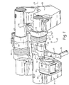
- FIG. 1 is a fragmentary, perspective view illustrating a valve deactivator installation, including a pair of deactivator assemblies, for operating both an intake valve and an exhaust valve.
- FIG. 2 is a fragmentary, cross-section, with various parts of the engine removed for ease of illustration, and taken through one of the rocker arms of the closer deactivator assembly in FIG. 1, and viewed from left to right in FIG. 1.
- FIG. 3 is a generally horizontal cross-section, viewed upward in FIG. 1, but on a larger scale than FIG. 1, illustrating the rocker arm assembly of the present invention.
- FIG. 4 is a generally vertical cross-section of the actuator which comprises part of the present invention.
- FIG. 5 is a somewhat schematic view, similar to FIG. 2, illustrating the spatial relationship of the various elements of the valve deactivator assembly of the present invention.
-
- Referring now to the drawings, which are not intended to limit the invention, FIGS. 1 and 2 illustrate a valve actuating drive train of the push rod type, although it should be understood that the use of the present invention is not strictly limited to use in a push rod type engine. In FIGS. 1 and 2, and for simplicity of illustration, the engine block and the cylinder head have been omitted, although both the block and the head will be referenced in the subsequent description, simply as a point of reference, and not by way of limitation of the invention.
- Disposed within the engine block is a drive assembly, generally designated 11, and disposed within the cylinder head is a
rocker arm assembly 13 and an enginepoppet valve assembly 15. The drive assembly 11 includes acam shaft 17 having acam 19, ahydraulic roller follower 21, and apush rod 23. Typically, theroller follower 21 would be disposed within a bore in the engine block, for reciprocation therein in response to the rotation of thecam 19. Thecam 19 includes alift portion 25 and a dwell (base circle)portion 27, as is well known to those skilled in the art. - The
poppet valve assembly 15 includes anengine poppet valve 29, operable to control flow to and from a combustion chamber, generally designated C, and further includes aspring 31 which biases thepoppet valve 29 toward a closed position in engagement with a valve seat S, as is also well known to those skilled in the art. - Referring now primarily to FIG. 1, the
rocker arm assembly 13 is mounted on arocker shaft 33, the opposite ends of which are supported byshaft support members members engine poppet valve 29 is shown, but with thespring 31 being removed, for ease of illustration. - Referring now to FIG. 3, in conjunction with FIG. 1, the
rocker arm assembly 13 includes an input or driverocker arm 39 and an output or drivenrocker arm 41. Thedrive rocker arm 39 includes amember 43 which is preferably pressed onto the push rod end (fight end in FIGS. 1 and 3) of thedrive rocker arm 39. Themember 43 includes a generally radially extending portion 45 (shown only in FIGS. 1, 2 and 5) adapted to engage the upper end of thepush rod 23. Thus, the cyclical motion imparted to theroller follower 21 andpush rod 23 by thecam 19 is translated into a cyclical, pivotal movement of thedrive rocker arm 39. - The driven
rocker arm 41 includes a radially extendingportion 47, the underside of which (shown in FIG. 3) is adapted for engagement with the upper end (tip portion) of the stem of thepoppet valve 29. - Referring still primarily to FIGS. 1 and 3, the
rocker arm assembly 13 includes a lostmotion spring 49, most of which surrounds the main, cylindrical portion of the drive rocker arm 39 (as is best shown in FIG. 3). Thus, themember 43 is pressed onto thedrive rocker arm 39 after the lostmotion spring 49 is in place. The lostmotion spring 49 includes aninput end 51, extending generally parallel to an axis of rotation A of therocker shaft 33. Theinput end 51 of thespring 49 is seated against a stop portion 53 (see FIG. 1). The lostmotion spring 49 also includes anoutput end 55, which also extends axially, anoutput end 55 being seen best on the valve deactivator assembly in the background portion of FIG. 1. The drivenrocker arm 41 includes astop portion 57, to help insure that theoutput end 55 of thespring 49 remains in engagement with the surface of the drivenrocker arm 41, as is shown in FIG. 2. - The drive and driven
rocker arms boss portions boss portions latch chamber 63 which, in the subject embodiment, is generally cylindrical, and defines an axis of rotation A1. Disposed within thelatch chamber 63 is acylindrical latch member 65, shown in FIG. 3 in the unlatched condition, fully retracted within thelatch chamber 63 against the biasing force of alatch bias spring 67. - Also disposed within the
latch chamber 63 is a generallycylindrical actuation member 69. Theactuation member 69 defines anannular groove 71, and received within thegroove 71 is asnap ring 73. Thelatch chamber 63 defines an axially extendingannular groove 75, sized to receive the radially outer portion of thesnap ring 73, thus permitting axial movement of theactuation member 69, but limiting such movement to the axial extent of the engagement of thesnap ring 73 within thegroove 75. Preferably, theactuation member 69 includes anengagement surface 77, shown in FIG. 3 as being generally concave, for reasons which will become apparent subsequently. - Referring now primarily to FIG. 4, in conjunction with FIG. 1, there is illustrated an actuator assembly, generally designated 81. The
actuator assembly 81 includes a generallyrectangular housing member 83 which is preferably fixed in a stationary manner, such as by being attached to the adjacentshaft support member 37. Thehousing member 83 also serves the function of providing a flux path as will become apparent subsequently. - Disposed within the
housing member 83 is anelectromagnetic coil 85, wound about asupport bobbin 87, thecoil 85 being energized when it receives an appropriate electrical input signal by means of a pair ofelectrical leads 88, shown only schematically herein. The reference numeral "88" will also be used hereinafter for the electrical input signal itself. Disposed within thebobbin 87 is a fixedpole piece 89, which is attached to be stationary relative to thehousing member 83. Also disposed within thebobbin 87 is amoveable pole piece 91, also typically referred to as an "armature". Fixed to thepole piece 91, and moveable therewith is anactuation shaft 93 which passes through a cylindrical opening in the fixedpole piece 89, and is in sliding engagement therewith. Theactuation shaft 93 and the moveable pole piece define an axis of rotation A2, which will be referred to subsequently. Anactuator head 95 is preferably formed integrally with theactuation shaft 93, and is disposed outside of thepole piece 89, the function of theactuator head 95 to be described subsequently. - Attached to the outside (right side in FIGS. 1 and 4) of the
housing member 83 is anactuator beam 97 which may be viewed as an output member of theactuator assembly 81. Preferably, theactuator beam 97 is formed from spring steel and includes a lower, generallyU-shaped spring portion 99. It is the left leg in FIG. 4 of thespring portion 99 which is anchored to thehousing member 83, the attachment being shown herein as comprising a pair of threaded stud and nut assemblies 101 (see also FIG. 5). Theactuator beam 97, above theU-shaped portion 99, is formed as a three-sided channel (see also FIG. 1). Thus, theactuator head 95 is received within the channel-shapedbeam 97, and is able to transmit linear movement of theactuation shaft 93 into pivotal movement of theactuator beam 97. One important feature of the invention is that theactuator beam 97 results in a mechanical advantage in moving theactuation member 69. As theactuation shaft 93 moves to the right in FIG. 4, the upper end of thebeam 97 moves a greater distance, linearly, than does theactuator head 95. - With the
electromagnetic coil 85 de-energized, thespring portion 99 of thebeam 97 biases thebeam 97, thepole piece 91 andactuation shaft 93 to the de-activated position shown in FIG. 4. Whenever an appropriateelectrical input signal 88 is transmitted to thecoil 85, the lines of flux pass through thehousing 83, the fixedpole piece 89 and themoveable pole piece 91, and bias thepole piece 91 and theactuation shaft 93 to the right in FIG. 4, against the biasing force of thespring portion 99, moving theactuator beam 97 to the right. - During normal operation, the
actuator assembly 81 is de-energized, such that theactuator beam 97 is biased to the unactuated position shown in FIGS. 1 and 4, thus permitting thelatch bias spring 67 to bias thelatch member 65 and theactuation member 69 to the left in FIG. 3. With thelatch member 65 and theactuation member 69 biased to the left, theengagement surface 77 remains in contact with the actuator beam 97 (as shown in FIG. 1). When thelatch member 65 moves to the left in FIG. 3 under the influence of thespring 67, thelatch member 65 is then in its latched condition interconnecting theboss portions rocker arms - Therefore, with the
rocker arm assembly 13 in the latched condition, cyclical motion of thepush rod 23 in response to rotation of thecam 19 will cause pivotal movement of therocker arms rocker shaft 33, causing cyclical opening and closing of thepoppet valve 29. In other words, in the latched condition, the operation of the valve gear train is the same as if therocker arms - When it becomes desirable to deactivate the
poppet valve 29, an appropriateelectrical signal 88 is transmitted to theelectromagnetic coil 85. This is initiated while theroller follower 21 is in engagement with thebase circle portion 27 of thecam 19 because, during the base circle portion of the valve event, the valve gear train is not under any substantial load. Therefore, it is in such an unloaded condition that it is desirable to change from the latched condition to the unlatched condition, or vice versa, for reasons which are well known to those skilled in the art. When thecoil 85 is energized, thepole piece 91 andactuation shaft 93 move to the right, as described previously, biasing theactuator beam 97 to the right in FIG. 4. This rightward movement of thebeam 97 overcomes the force of thelatch bias spring 67 and moves thelatch member 65 andactuation member 69 to the fully retracted, unlatched condition shown in FIG. 3. - Preferably, this change from the latched condition to the unlatched condition is completed between the time that the
roller follower 21 first engages thebase circle portion 27 and the time thefollower 21 begins to engage thelift portion 25. Once thedrive rocker arm 39 is unlatched from the drivenrocker arm 41, the cyclical motion of thepush rod 23 will cause thedrive rocker arm 39 to pivot about therocker shaft 33. As therocker arm 39 pivots (rotates clockwise in FIGS. 2 and 5) the lostmotion spring 49 is "compressed", i.e., wound up about thedrive rocker arm 39 because of the engagement of thestop portion 53 and theinput end 51 of thespring 49. With thedrive rocker arm 39 unlatched from the drivenrocker arm 41, theboss portion 59 also moves clockwise (in FIG. 2) relative to theboss portion 61. However, theoutput end 55 of thespring 49 remains in engagement with theboss portion 61, which is not rotating, because it is now unlatched from the boss portion 59 (as shown in FIG. 3) and the biasing force of thespring 31, biasing theengine poppet valve 29 closed, is substantially greater than the biasing force of the lostmotion spring 49. Preferably, the biasing force of the lostmotion spring 49 is sufficient that, if theroller follower 21 includes a hydraulic lash compensation device, thespring 49 must be able to prevent the lash compensation device from "pumping up", i.e., extending more than is needed to compensate for lash in the valve gear train. - Therefore, with the drive and driven
rocker arms rocker arm 41 remains stationary, under the influence of thespring 31, and thepoppet valve 29 remains closed. After each pivotal movement of thedrive rocker arm 39, theboss portions output end 55 of the lostmotion spring 49. - Referring now primarily to FIG. 5, it may be seen that the arrangement of the present invention provides a compact, effective package. In FIG. 5, the axis of rotation A1 of the
latch chamber 63 is disposed at a distance L1 from the axis A of therocker shaft 33, whereas the axis of rotation A2 of theactuation shaft 93 is disposed at a distance L2 from the axis A. It is desirable for thelatch chamber 63 to be located as close as possible to the axis A of therocker shaft 33, but the necessary size of theactuator assembly 81 requires that the axis A2 be further away from the axis A. For this reason, among others, direct electromagnetic actuation of the latching arrangement would not be feasible, but the "indirect" actuation of the present invention, by means of theactuation beam 97, enables each of thelatch chamber 63 and theactuator assembly 81 to be mounted where necessary. - It may be seen that the present invention provides a substantially improved valve deactivator assembly which is compact and can be added to an existing design of a push rod and rocker shaft type engine. In a typical engine of that type, all that is required, by way of redesign of the engine, is to replace the existing rocker arm with the rocker arm assembly shown in FIG. 3, and mount the
actuator assembly 81 shown in FIG. 4. - Although the invention has hereinabove been described with respect to the illustrated embodiments, it will be understood that the invention is capable of modification and variation and is limited only by the following claims.
Claims (12)
- A valve deactivator assembly (13) for an internal combustion engine of the type having valve means (15) for controlling the flow to and from a combustion chamber (C), drive means (11) for providing cyclical motion for opening and closing said valve means (15) in timed relationship to the events in said combustion chamber (C) and valve gear means, operative in response to said cyclical motion, to effect cyclical opening and closing of said valve means (15); said valve gear means including a rocker shaft (33) and a rocker arm assembly mounted to be pivotable about said rocker shaft, in response to said cyclical motion of said drive means (11); said rocker arm assembly including a drive rocker arm (39) and a driven rocker arm (41) disposed axially adjacent each other, and each being pivotable about said rocker shaft (33); characterized by:(a) means (23) for transmitting said cyclical motion from said drive means (11) to said drive rocker arm (39);(b) said driven rocker arm (41) being adapted to transmit said cyclical motion to said valve means (15);(c) said drive (39) and driven (41) rocker arms cooperating to define a latch chamber (63);(d) a latch member (65) disposed in said latch chamber (63) and including means (67) biasing said latch member (65) toward a latched position (FIG. 1), interconnecting said drive (39) and driven (41) rocker arms for pivotable movement in unison;(e) electromagnetic actuation means (81) disposed adjacent said rocker arms (39,41) and operable, in response to an electrical input signal (88) to move said latch member (65) toward an unlatched position (FIG. 3) permitting pivotal movement of said drive rocker arm (39) relative to said driven rocker arm (41).
- A valve deactivator assembly (13) as claimed in claim 1, characterized by said drive means comprising a cam shaft (17) having a cam (19) defining a base circle portion (27) and a lift portion (25).
- A valve deactivator assembly (13) as claimed in claim 2, characterized by said valve gear means comprises a cam follower (21) in engagement with said cam (19) and a push rod (23) in operable engagement with said cam follower (21) and with said drive rocker arm (39), said push rod (23) comprising said means for transmitting said cyclical motion from said drive means (11).
- A valve deactivator assembly (13) as claimed in claim 3, characterized by said cam follower (21) comprises a lash compensation element reciprocably disposed within said cam follower (21).
- A valve deactivator assembly (13) as claimed in claim 1, characterized by said latch chamber (63) being generally cylindrical and defining a first axis (A1) oriented generally parallel to an axis (A) defined by said rocker shaft (33 ).
- A valve deactivator assembly (13) as claimed in claim 5, characterized by an actuation member (69) being disposed within said latch chamber (63) and disposed axially between said latch member (65) and an output member (97) of said electromagnetic actuation means (81).
- A valve deactivator assembly (13) as claimed in claim 6, characterized by said actuation member (69) including a terminal portion (77) in engagement with said output member (97) and disposed external to said latch chamber (63) when said latch member (65) is in said latched position (FIG. 1).
- A valve deactivator assembly (13) as claimed in claim 5, characterized by said electromagnetic actuation means (81) comprising a fixed pole piece (89), an electromagnetic coil (85), and an armature (91) movable in response to changes in said electrical input signal (88), said armature (91) defining a second axis (A2) oriented generally parallel to said axis (A) of said rocker shaft (33).
- A valve deactivator assembly (13) as claimed in claim 8, characterized by said first axis (A1) being disposed at a first distance (L1) from said axis (A) of said rocker shaft (33) and said second axis (A2) being disposed at a second distance (L2) from said axis (A) of said rocker shaft, said second distance (L2) being substantially greater than said first distance (L1).
- A valve deactivator assembly (13) as claimed in claim 9, characterized by said electromagnetic actuation means (81) including an output member (97) operable to move said latch member (65), and operably associated with said armature (91), said output member (97) being configured whereby movement of said armature (91) over a first distance results in movement of said latch member (65) over a second distance, said second distance being greater than said first distance.
- A valve deactivator assembly (13) as claimed in claim 4, characterized by a lost motion spring (49) operably associated with said drive (39) and driven (41) rocker arms to bias said rocker arms toward a position relative to each other in which said rocker arms cooperate to define said latch chamber (63), said lost motion spring (49) having sufficient biasing force to overload said lash compensation element.
- A valve deactivator assembly (13) as claimed in claim 11, characterized by said lost motion spring comprising a torsional spring member (49) disposed in partially surrounding relationship to one of said drive (39) and driven (41) rocker arms, and including first (51) and second (55) ends, rotationally fixed relative to said drive (39) and driven (41) rocker arms, respectively.
Applications Claiming Priority (2)
| Application Number | Priority Date | Filing Date | Title |
|---|---|---|---|
| US256272 | 1999-02-23 | ||
| US09/256,272 US6092497A (en) | 1997-10-30 | 1999-02-23 | Electromechanical latching rocker arm valve deactivator |
Publications (2)
| Publication Number | Publication Date |
|---|---|
| EP1031705A2 true EP1031705A2 (en) | 2000-08-30 |
| EP1031705A3 EP1031705A3 (en) | 2001-09-26 |
Family
ID=22971615
Family Applications (1)
| Application Number | Title | Priority Date | Filing Date |
|---|---|---|---|
| EP00301221A Withdrawn EP1031705A3 (en) | 1999-02-23 | 2000-02-16 | Electromechanical latching rocker arm valve deactivator |
Country Status (2)
| Country | Link |
|---|---|
| US (1) | US6092497A (en) |
| EP (1) | EP1031705A3 (en) |
Cited By (5)
| Publication number | Priority date | Publication date | Assignee | Title |
|---|---|---|---|---|
| DE10155827A1 (en) * | 2001-11-14 | 2003-05-15 | Ina Schaeffler Kg | Rocker arm used in a valve gear of an internal combustion engine has an outer lever having arms, and an inner lever having a running surface for a cam |
| DE10155801A1 (en) * | 2001-11-14 | 2003-05-22 | Ina Schaeffler Kg | Rocker arm used in a valve gear of an internal combustion engine comprises an external rocker having an inner rocker positioned between its arms which pivot relative to each other |
| EP1277924A3 (en) * | 2001-07-16 | 2003-11-05 | Delphi Technologies, Inc. | Mechanical assist actuation bracket for deactivation and two-step roller finger followers |
| DE10314683A1 (en) * | 2003-03-29 | 2004-11-11 | BÖSL-FLIERL, Gerlinde | Variable valve lift control for an internal combustion engine with a camshaft at the bottom |
| EP1674672A1 (en) * | 2004-12-27 | 2006-06-28 | Caterpillar Motoren GmbH & Co. | Control system for a variable valve actuating device |
Families Citing this family (30)
| Publication number | Priority date | Publication date | Assignee | Title |
|---|---|---|---|---|
| US7263956B2 (en) | 1999-07-01 | 2007-09-04 | Delphi Technologies, Inc. | Valve lifter assembly for selectively deactivating a cylinder |
| US6578535B2 (en) * | 1999-07-01 | 2003-06-17 | Delphi Technologies, Inc. | Valve-deactivating lifter |
| US6513470B1 (en) * | 2000-10-20 | 2003-02-04 | Delphi Technologies, Inc. | Deactivation hydraulic valve lifter |
| US6276138B1 (en) * | 1999-09-10 | 2001-08-21 | Ford Global Technologies, Inc. | Engine with direct turbo compounding |
| US6349688B1 (en) * | 2000-02-18 | 2002-02-26 | Briggs & Stratton Corporation | Direct lever overhead valve system |
| US6418904B2 (en) | 2000-04-03 | 2002-07-16 | Daimlerchrysler Corporation | Pulse drive valve deactivator |
| JP3876589B2 (en) * | 2000-05-11 | 2007-01-31 | いすゞ自動車株式会社 | Valve deactivation mechanism for cylinder-controlled engines |
| ES2253197T3 (en) * | 2000-09-06 | 2006-06-01 | Eaton S.R.L. | CONTROL UNIT OF THE VALVE RACE WITH SIMPLIFIED LUBRICATION. |
| JP4466897B2 (en) * | 2001-04-03 | 2010-05-26 | ヤマハ発動機株式会社 | High and low speed switching valve mechanism for internal combustion engine |
| DE10146129A1 (en) | 2001-09-19 | 2003-04-03 | Ina Schaeffler Kg | Switching element for a valve train of an internal combustion engine |
| WO2003067038A1 (en) * | 2002-02-06 | 2003-08-14 | Ina-Schaeffler Kg | Switch element for valve actuation in an internal combustion engine |
| US6745733B2 (en) * | 2002-02-21 | 2004-06-08 | Delphi Technologies, Inc. | Actuating system for mode-switching rocker arm device |
| US6666178B1 (en) * | 2002-08-08 | 2003-12-23 | Eaton Corporation | Valve deactivation with an electro-hydraulic actuator |
| JP4137584B2 (en) * | 2002-10-11 | 2008-08-20 | 本田技研工業株式会社 | Cylinder operation control device for internal combustion engine |
| US7273026B2 (en) | 2002-10-18 | 2007-09-25 | Maclean-Fogg Company | Roller follower body |
| US7128034B2 (en) | 2002-10-18 | 2006-10-31 | Maclean-Fogg Company | Valve lifter body |
| US7028654B2 (en) | 2002-10-18 | 2006-04-18 | The Maclean-Fogg Company | Metering socket |
| US6871622B2 (en) | 2002-10-18 | 2005-03-29 | Maclean-Fogg Company | Leakdown plunger |
| US7191745B2 (en) | 2002-10-18 | 2007-03-20 | Maclean-Fogg Company | Valve operating assembly |
| US7040265B2 (en) * | 2003-06-03 | 2006-05-09 | Daimlerchrysler Corporation | Multiple displacement system for an engine |
| US20040244751A1 (en) * | 2003-06-03 | 2004-12-09 | Falkowski Alan G. | Deactivating valve lifter |
| US6988473B2 (en) * | 2003-06-26 | 2006-01-24 | Delphi Technologies, Inc. | Variable valve actuation mechanism having an integrated rocker arm, input cam follower and output cam body |
| US6935295B2 (en) * | 2003-09-24 | 2005-08-30 | General Motors Corporation | Combustion-assisted engine start/stop operation with cylinder/valve deactivation |
| DE102008057830A1 (en) * | 2007-11-21 | 2009-05-28 | Schaeffler Kg | Switchable plunger |
| JP5139113B2 (en) * | 2008-02-19 | 2013-02-06 | ヤマハ発動機株式会社 | Variable valve gear |
| US8196556B2 (en) * | 2009-09-17 | 2012-06-12 | Delphi Technologies, Inc. | Apparatus and method for setting mechanical lash in a valve-deactivating hydraulic lash adjuster |
| FR2995935B1 (en) * | 2012-09-25 | 2015-07-31 | Valeo Sys Controle Moteur Sas | TRANSMISSION ASSEMBLY FOR MOVING AT LEAST ONE CAM |
| WO2018208857A1 (en) * | 2017-05-08 | 2018-11-15 | Eaton Intelligent Power Limited | Leaf spring sliding contact for electrically latched rocker arm assembly |
| CN112771250B (en) | 2018-09-04 | 2024-03-08 | 伊顿智能动力有限公司 | Direct-acting solenoid with variable trigger timing for electromechanical valvetrain and actuation lever for switching rocker arms |
| US11891923B2 (en) * | 2019-09-10 | 2024-02-06 | Eaton Intelligent Power Limited | Valvetrain with rocker shaft housing magnetic latch |
Citations (3)
| Publication number | Priority date | Publication date | Assignee | Title |
|---|---|---|---|---|
| US4576128A (en) | 1983-12-17 | 1986-03-18 | Honda Giken Kogyo Kabushiki Kaisha | Valve operation stopping means for multi-cylinder engine |
| US5592907A (en) | 1994-08-25 | 1997-01-14 | Honda Giken Kogyo Kabushiki Kaisha | Valve operating system for multi-cylinder internal combustion engine |
| US5613469A (en) | 1995-12-26 | 1997-03-25 | Chrysler Corporation | Controls apparatus for engine variable valve system |
Family Cites Families (14)
| Publication number | Priority date | Publication date | Assignee | Title |
|---|---|---|---|---|
| US4252093A (en) * | 1977-08-08 | 1981-02-24 | Hazelrigg Henry A | Internal combustion engine |
| JPH061044B2 (en) * | 1985-02-12 | 1994-01-05 | スズキ株式会社 | Variable valve opening / closing timing device for 4-cycle engine |
| JPS61185605A (en) * | 1985-02-12 | 1986-08-19 | Suzuki Motor Co Ltd | Valve open/close timing varying device for four-cycle engine |
| JPH01285611A (en) * | 1988-05-10 | 1989-11-16 | Honda Motor Co Ltd | Valve working state switching device for internal combustion engine |
| JPH0533618A (en) * | 1990-05-01 | 1993-02-09 | Nissan Motor Co Ltd | Engine valve actuation |
| JP2955010B2 (en) * | 1990-11-28 | 1999-10-04 | マツダ株式会社 | Valve train for multi-cylinder engine |
| US5307769A (en) * | 1993-06-07 | 1994-05-03 | General Motors Corporation | Low mass roller valve lifter assembly |
| DE59400590D1 (en) * | 1993-11-08 | 1996-10-10 | Daimler Benz Ag | Device for operating valves of an internal combustion engine |
| US5660153A (en) * | 1995-03-28 | 1997-08-26 | Eaton Corporation | Valve control system |
| US5653198A (en) * | 1996-01-16 | 1997-08-05 | Ford Motor Company | Finger follower rocker arm system |
| US5908015A (en) * | 1996-07-06 | 1999-06-01 | Meta Motoren- Und Energie Technik Gmbh | Arrangement for interrupting the flow of force between a camshaft and a valve |
| EP0834647B1 (en) * | 1996-10-07 | 2002-07-03 | Yamaha Hatsudoki Kabushiki Kaisha | Engine valve actuating system |
| US5697333A (en) * | 1997-02-20 | 1997-12-16 | Eaton Corporation | Dual lift actuation means |
| US5893344A (en) * | 1998-07-13 | 1999-04-13 | Eaton Corporation | Valve deactivator for pedestal type rocker arm |
-
1999
- 1999-02-23 US US09/256,272 patent/US6092497A/en not_active Expired - Lifetime
-
2000
- 2000-02-16 EP EP00301221A patent/EP1031705A3/en not_active Withdrawn
Patent Citations (3)
| Publication number | Priority date | Publication date | Assignee | Title |
|---|---|---|---|---|
| US4576128A (en) | 1983-12-17 | 1986-03-18 | Honda Giken Kogyo Kabushiki Kaisha | Valve operation stopping means for multi-cylinder engine |
| US5592907A (en) | 1994-08-25 | 1997-01-14 | Honda Giken Kogyo Kabushiki Kaisha | Valve operating system for multi-cylinder internal combustion engine |
| US5613469A (en) | 1995-12-26 | 1997-03-25 | Chrysler Corporation | Controls apparatus for engine variable valve system |
Cited By (7)
| Publication number | Priority date | Publication date | Assignee | Title |
|---|---|---|---|---|
| EP1277924A3 (en) * | 2001-07-16 | 2003-11-05 | Delphi Technologies, Inc. | Mechanical assist actuation bracket for deactivation and two-step roller finger followers |
| DE10155827A1 (en) * | 2001-11-14 | 2003-05-15 | Ina Schaeffler Kg | Rocker arm used in a valve gear of an internal combustion engine has an outer lever having arms, and an inner lever having a running surface for a cam |
| DE10155801A1 (en) * | 2001-11-14 | 2003-05-22 | Ina Schaeffler Kg | Rocker arm used in a valve gear of an internal combustion engine comprises an external rocker having an inner rocker positioned between its arms which pivot relative to each other |
| DE10314683A1 (en) * | 2003-03-29 | 2004-11-11 | BÖSL-FLIERL, Gerlinde | Variable valve lift control for an internal combustion engine with a camshaft at the bottom |
| DE10314683B4 (en) * | 2003-03-29 | 2009-05-07 | Entec Consulting Gmbh | Variable valve lift control for a combustion engine with a bottom camshaft |
| US7712442B2 (en) | 2003-03-29 | 2010-05-11 | Entec Consulting Gmbh | Variable valve lift control system for a combustion engine with underneath camshaft |
| EP1674672A1 (en) * | 2004-12-27 | 2006-06-28 | Caterpillar Motoren GmbH & Co. | Control system for a variable valve actuating device |
Also Published As
| Publication number | Publication date |
|---|---|
| US6092497A (en) | 2000-07-25 |
| EP1031705A3 (en) | 2001-09-26 |
Similar Documents
| Publication | Publication Date | Title |
|---|---|---|
| US6092497A (en) | Electromechanical latching rocker arm valve deactivator | |
| US6273039B1 (en) | Valve deactivating roller following | |
| US5893344A (en) | Valve deactivator for pedestal type rocker arm | |
| US4777915A (en) | Variable lift electromagnetic valve actuator system | |
| US5199392A (en) | Electromagnetically operated adjusting device | |
| US4719882A (en) | Electromagnetic-positioning system for gas exchange valves | |
| US6196175B1 (en) | Hydraulically actuated valve deactivating roller follower | |
| US5690066A (en) | Engine valve control actuator with knee action linkage | |
| US5524580A (en) | Adjusting mechanism for a valve control system | |
| CA1275015A (en) | Electromagnetically-actuated positioning mechanism | |
| US5762035A (en) | Electromagnetic cylinder valve actuator having a valve lash adjuster | |
| US6412461B2 (en) | Valve resting mechanism for cylinder control type engine | |
| EP3363998B1 (en) | Switchable rocker arm with a travel stop | |
| US5697333A (en) | Dual lift actuation means | |
| EP0347211B1 (en) | Valve operation control system of internal combustion engine | |
| US6085704A (en) | Electromagnetically operating actuator for intake and/or exhaust valves | |
| JPH108929A5 (en) | ||
| US5813653A (en) | Electromagnetically controlled regulator | |
| US4711207A (en) | Valve deactivator mechanism | |
| US4337738A (en) | Valve control mechanism | |
| US5961097A (en) | Electromagnetically actuated valve with thermal compensation | |
| US6082315A (en) | Electromagnetic valve actuator | |
| US5704314A (en) | Electromagnetic operating arrangement for intake and exhaust valves of internal combustion engines | |
| US5927237A (en) | Valve operating system in internal combustion engine | |
| US6394416B2 (en) | Device for operating a gas exchange valve |
Legal Events
| Date | Code | Title | Description |
|---|---|---|---|
| PUAI | Public reference made under article 153(3) epc to a published international application that has entered the european phase |
Free format text: ORIGINAL CODE: 0009012 |
|
| AK | Designated contracting states |
Kind code of ref document: A2 Designated state(s): AT BE CH CY DE DK ES FI FR GB GR IE IT LI LU MC NL PT SE |
|
| AX | Request for extension of the european patent |
Free format text: AL;LT;LV;MK;RO;SI |
|
| PUAL | Search report despatched |
Free format text: ORIGINAL CODE: 0009013 |
|
| AK | Designated contracting states |
Kind code of ref document: A3 Designated state(s): AT BE CH CY DE DK ES FI FR GB GR IE IT LI LU MC NL PT SE |
|
| AX | Request for extension of the european patent |
Free format text: AL;LT;LV;MK;RO;SI |
|
| AKX | Designation fees paid | ||
| REG | Reference to a national code |
Ref country code: DE Ref legal event code: 8566 |
|
| STAA | Information on the status of an ep patent application or granted ep patent |
Free format text: STATUS: THE APPLICATION IS DEEMED TO BE WITHDRAWN |
|
| 18D | Application deemed to be withdrawn |
Effective date: 20020327 |