EP0834647B1 - Engine valve actuating system - Google Patents
Engine valve actuating system Download PDFInfo
- Publication number
- EP0834647B1 EP0834647B1 EP97117316A EP97117316A EP0834647B1 EP 0834647 B1 EP0834647 B1 EP 0834647B1 EP 97117316 A EP97117316 A EP 97117316A EP 97117316 A EP97117316 A EP 97117316A EP 0834647 B1 EP0834647 B1 EP 0834647B1
- Authority
- EP
- European Patent Office
- Prior art keywords
- rocker arm
- valve
- operating mechanism
- set forth
- cam
- Prior art date
- Legal status (The legal status is an assumption and is not a legal conclusion. Google has not performed a legal analysis and makes no representation as to the accuracy of the status listed.)
- Expired - Lifetime
Links
Images


Classifications
-
- F—MECHANICAL ENGINEERING; LIGHTING; HEATING; WEAPONS; BLASTING
- F01—MACHINES OR ENGINES IN GENERAL; ENGINE PLANTS IN GENERAL; STEAM ENGINES
- F01L—CYCLICALLY OPERATING VALVES FOR MACHINES OR ENGINES
- F01L1/00—Valve-gear or valve arrangements, e.g. lift-valve gear
- F01L1/26—Valve-gear or valve arrangements, e.g. lift-valve gear characterised by the provision of two or more valves operated simultaneously by same transmitting-gear; peculiar to machines or engines with more than two lift-valves per cylinder
- F01L1/267—Valve-gear or valve arrangements, e.g. lift-valve gear characterised by the provision of two or more valves operated simultaneously by same transmitting-gear; peculiar to machines or engines with more than two lift-valves per cylinder with means for varying the timing or the lift of the valves
Definitions
- variable valve timing and variable valve lift have been proposed for achieving either or both of the variable valve timing and variable valve lift. For the most part, however, they are fairly complex and add significantly to the complexity of the valve train.
- DE-A-36 13 945 and corresponding US-A-4 726 332 disclose a variable valve mechanism for an engine including a first rocker arm engaged at one end with the valve tappet and at the other end with a low speed profile cam, and a second rocker arm engaged with a high speed profile cam.
- a locking device is provided on the second rocker arm to releasably lock the second rocker arm on the first rocker arm under a high speed engine operation.
- This invention is adapted to be embodied in the valve actuating mechanism for operating a single poppet valve of an engine through cooperation with the stem thereof.
- the valve operating mechanism is comprised of a single cam shaft having a pair of adjacent cams.
- a pair of adjacent, pivotally supported rocker arms each cooperate with a respective one of the cams.
- a first of the rocker arms has an operating portion for direct cooperation with the valve stem for operating the valve.
- Means provide a selective coupling of the second rocker arm to the first rocker arm for effecting actuation of the valve through the first rocker arm.
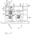
- Figure 1 is a top plan view looking at the valve actuating mechanism associated with a single cylinder of an internal combustion engine constructed in accordance with a first embodiment of the invention, with the cam cover for the engine removed.
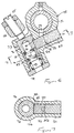
- Figure 2 is an exploded view showing the same components illustrated in Figure 1 but illustrating only the cam shaft and the rocker arms associated therewith.
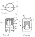
- Figure 3 is a cross-sectional view taken along the line 3-3 of Figure 1 and illustrates one of the rocker arms and its association with the cam shaft.
- Figure 4 is a cross-sectional view taken along the line 4-4 of Figure 1 and shows the valve in its closed position.
- Figure 5 is a cross-sectional view, in part similar to Figure 4, and shows the valve in its open position when opened by the first rocker arm.
- Figure 6 is an enlarged cross-sectional view taken along the same plane as Figures 4 and 5, and shows the same condition as in Figure 4, i.e., with the valve closed.
- Figure 7 is a cross-sectional view taken along the line 7-7 of Figure 6.
- Figure 15 is a view, in part similar to Figure 1, and shows another embodiment of the invention where both valves of the same cylinder are operated by variable valve actuating mechanisms.
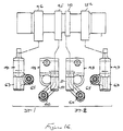
- Figure 16 is a partially exploded view, in part similar to Figure 2, but shows the cam shaft and rocker arms of this embodiment.
- Figure 18 is an exploded view, in part similar to Figures 2 and 16, but shows the cam shaft and rocker arms for this embodiment.
- Figure 19 is a top plan view, in part similar to Figures 1, 15 and 17, and shows yet another embodiment of the invention wherein both valves associated with the same cylinder has a variable valve actuating mechanism but, in this embodiment, sharing one of the rocker arms.
- Figure 21 is a cross-sectional view, in part similar to Figure 3, but shows another type of biasing arrangement for the second rocker arm.
- a portion of a cylinder head assembly of an internal combustion engine is illustrated and is identified generally by the reference numeral 31. Only a portion of the engine is illustrated and specifically the cylinder head thereof because the invention deals, as aforenoted, with a valve actuating mechanism for engines. Therefore, when any details of the construction of the engine are not illustrated, they may be considered to be conventional. Those skilled in the art will be able to determine from the following description how the invention can be utilized with a wide variety of engines.
- each cylinder of the engine is served by a pair of intake passages 35 that terminate in valve seats 36 which are valved by poppet-type intake valves, indicated generally by the reference numeral 37.
- These valves 37 have head portions 38 that cooperate with the valve seats 36 and stem portions 39 that are slidably supported in valve guides 41 affixed to the cylinder head member 32.
- keeper retainer assemblies 42 retain spring assemblies 43 that act between the keeper retainer assemblies 42 and the cylinder head for biasing the valves 37 to their closed positions, as is well-known in this art.
- the rocker arm 49 has an outwardly extending arm which forms an integral follower 63 that is engaged by the cam lobe 46.
- the cam lobe 46 is of a larger lift and larger diameter than that of the cam lobe 45.
- this cam lobe 46 may also be configured to provide slightly different timing through its cooperation with the first rocker arm 48.
- the spring arrangement includes an outer cylinder member 68 which defines a bore in which a sliding biasing member 69 is provided.
- the sliding biasing member 69 is biased by a coil compression spring 71 into engagement with a further follower surface 72 formed on a portion of the rocker arm 49 that extends in somewhat diametrical opposition to the portion that forms the follower surface 63.
- the spring 71 acting through the biasing member 69 and rocker arm surface 72 will maintain the rocker arm follower 63 in engagement with the cam lobe 46.
- the lower end of the bore 74 is partially closed by a cap 78 which forms an engagement for a biasing spring 79 that acts on the lower end of the coupling plunger member 76.
- This spring 79 keeps the coupling plunger member 76 and specifically its surface 77 in constant engagement with the adjusting screw 65. It should be apparent, however, that if desired, some clearance may be maintained in this gap depending upon how the valve operation is to be accomplished. Also in some views the position of the plunger member 76 in the bore may not be the true position depending upon the lift characteristics of the respective cams 45 and 46 and specifically that of their lobes.
- the coupling plunger member 76 is formed with a bore 81 that extends from a flat surface 82 formed in a side thereof by a machined recess 83. Received within the bore 81 is a return spring arrangement that is comprised of a pair of end caps 85 and 86 that are urged apart by a coil compression spring 87.
- this compression spring 87 causes the retaining member 86 to be urged to a position where a flat surface of it is coextensive with the surface 82. Under this condition the surface 82 is engaged by a slidable locking member 88.
- the locking member 88 is slidably supported within a bore 89 that extends through the rocker arm 48 below its journal on the rocker arm shaft 51. The outer end of this bore 89 is closed by a closure plug 91 and in the uncoupled state, the locking member 88 is abuttingly engaged with this closure plug 91.
- a gap 92 is provided between it and the end closure 91.
- This gap communicates with an oil control passage 93 that extends through the rocker arm shaft 51 and rocker arm 48.
- the rocker arm shaft 51 is hollow and hydraulic fluid pressure may be exerted selectively through this passage 73 to the area 92 in accordance with a desired control strategy.
- One such strategy will be described later by reference to the embodiment of Figure 14.
- rocker arm 51 and cam lobe 47 that operate the remaining intake valve which does not have its lift varied in this embodiment.
- the rocker arm 51 has a follower surface 94 that is engaged by the cam lobe 47.
- An adjusting screw 95 carried at the tip of this rocker arm cooperates with the stem of this valve to operate it in a normal manner.
- Varying types of lift arrangements may be employed and different lift ratios and/or valve timing between the non-variable actuated valve and the variable actuated valve. That is the lift and/or timing of the valve operated by the cam 47 may be the same as that provided by either of the cams 45 or 46 associated with the other valve or different from either of them.
- FIG 14 is a view that shows one way in which this mechanism may operate. This view shows the induction system schematically and it now will be described by reference to that Figure.
- the normally or non-variably actuated valve is indicated by the reference numeral 37-2, while the variably actuated valve is indicated by the reference numeral 37-1.
- the intake passages 35 associated therewith have also been indicated by the same suffixes, i.e., 35-2 and 35-1.
- an air inlet device draws atmospheric air through an inlet opening 102 in which a manually actuated throttle control valve 103 is positioned.
- the air inlet device 101 forms a plenum chamber 104 that communicates with the runners 35-1 and 35-2 of each cylinder.
- a control valve 105 is provided in the runner 35-2 and is operated by a servo motor 106 under the control of an ECU, indicated generally by the reference numeral 107.
- the intake valve 37-1 and its operation is adjusted to optimize primarily the low and mid-range performance of the engine.
- the cam lobe 45 and rocker arm 48 can be tailored for optimum performance under low-speed and low-mid range running.
- the cam lobe 46 and rocker arm 49 are coupled for a higher range of operation and may provide a substantially greater lift so as to improve the performance under higher speeds and loads.
- the ECU effects opening of the control valve 105 by the servo motor 106.
- the engine can provide very good performance under a wide variety of speeds and loads due to the use of the variable valve actuating mechanism and the control valve 105.
- the adjusting screw 65 In order to permit a compact assembly, obviously the adjusting screw 65 must be configured in relation to the cam lobes and specifically the cam lobe 45, so as to not present any interference.
- Figures 15 and 16 show another embodiment of the invention wherein both of the intake valves 37-1 and 37-2 are provided with a variable valve actuating mechanism.
- the cam shaft is provided with, in addition to, the lobes 45 and 46, for actuating the first intake valve 37-1, with additional lobes 151 and 152 for operating the rocker arms 48 and 49 associated with the remaining valve 37-2.
- rocker arms 48 and 49 associated with the second intake valve 37-2 are mirror images so as to permit the two rocker arms 48 to be positioned next to each other and the other two rocker arms to be spaced more widely. With this type of arrangement, as shown, the initial lift for the valve 37-2 is less than that of the valve 37-1 but the maximum lift provided by the cam lobes 46 and 152 can be the same.
- FIGS 19 and 20 show another embodiment wherein the second rocker arms for the two valves are integrated into a single rocker arm. Since that is the only difference between this embodiment and that shown in Figures 17 and 18, components which are the same are identified by the same reference numerals and will not be described again, except insofar as is necessary to understand the construction and operation of this embodiment.
- a single second rocker arm 201 for each of the valves 37-1 and 37-2 is provided .
- This rocker arm 201 has a single follower surface 202 that is engaged by a single cam lobe 203.
- This rocker arm has a pair of bosses 204 and 205 each of which carries a respective adjusting screw 206 and 207. These adjusting screws actuate the connecting system of the adjacent rocker arms 48, in the manner that has already been described.
- the arrangement can be further simplified.
- the operation of the second rocker arm 201 on each valve then must be the same. Different lift characteristics can be provided for the operation of the valves 37-1 and 37-2 and in this embodiment the lift of 37-1 is greater than that of 37-2 before the rocker arm 201 actuates both valves.
- Figures 21 and 22 show both the incorporation of the variable valve actuating mechanism for all valves of the engine and also shows a different biassing arrangement for the second rocker arms. Since this is the only main difference, components which are the same or substantially the same have been identified by the same reference numerals.
- the second rocker arms 48 have, on the opposite side from their follower surfaces 59, a protruding portion 251 that is engaged by a spring return mechanism which is in essence the same as that employed in and shown in detail in Figure 3.
- this return mechanism 67 is mounted directly in the cylinder head member 32 rather than on the cam carrier 33. In all other regards, this embodiment is the same and thus, further description of it is not believed to be necessary to permit those skilled in the art to practice the invention.
Landscapes
- Engineering & Computer Science (AREA)
- Mechanical Engineering (AREA)
- General Engineering & Computer Science (AREA)
- Valve Device For Special Equipments (AREA)
- Valve-Gear Or Valve Arrangements (AREA)
Description
- This invention relates to an engine valve actuating system and more particularly to an improved arrangement for achieving variable valve actuation (timing and/or lift) in the operation of an engine valve.
- As is well-known, many factors in an internal combustion engine represent a design compromise. Generally, the compromise is between achieving good low-speed performance and economy and high output and high power. There has been proposed a wide variety of devices, however, so as to permit the engine characteristics to be adjusted during its running, so as to obtain improved performance across the entire speed and load range. One of these features is variable valve actuation which includes both changing the valve timing and/or the valve lift. Obviously, these present substantial challenges to the engineer considering that the adjustment must be made when the engine is running.
- A wide variety of mechanisms have been proposed for achieving either or both of the variable valve timing and variable valve lift. For the most part, however, they are fairly complex and add significantly to the complexity of the valve train.
- DE-A-36 13 945 and corresponding US-A-4 726 332 disclose a variable valve mechanism for an engine including a first rocker arm engaged at one end with the valve tappet and at the other end with a low speed profile cam, and a second rocker arm engaged with a high speed profile cam. A locking device is provided on the second rocker arm to releasably lock the second rocker arm on the first rocker arm under a high speed engine operation.
- It is, therefore, a principal object of this invention to provide an improved variable valve actuating mechanism that is relatively simple in construction and which lends itself to incorporation in multi-valve engines.
- It is still further object of this invention to provide an improved valve operating mechanism for an engine that can achieve variable valve operation during engine running.
- These objects are achieved with the features of the claims.
- This invention is adapted to be embodied in the valve actuating mechanism for operating a single poppet valve of an engine through cooperation with the stem thereof. The valve operating mechanism is comprised of a single cam shaft having a pair of adjacent cams. A pair of adjacent, pivotally supported rocker arms, each cooperate with a respective one of the cams. A first of the rocker arms has an operating portion for direct cooperation with the valve stem for operating the valve. Means provide a selective coupling of the second rocker arm to the first rocker arm for effecting actuation of the valve through the first rocker arm. Thus, by providing different characteristics of the cam and rocker arms, varying lift and/or duration can be achieved.
- The invention will be described in detail in connection with the drawings.
- Figure 1 is a top plan view looking at the valve actuating mechanism associated with a single cylinder of an internal combustion engine constructed in accordance with a first embodiment of the invention, with the cam cover for the engine removed.
- Figure 2 is an exploded view showing the same components illustrated in Figure 1 but illustrating only the cam shaft and the rocker arms associated therewith.
- Figure 3 is a cross-sectional view taken along the line 3-3 of Figure 1 and illustrates one of the rocker arms and its association with the cam shaft.
- Figure 4 is a cross-sectional view taken along the line 4-4 of Figure 1 and shows the valve in its closed position.
- Figure 5 is a cross-sectional view, in part similar to Figure 4, and shows the valve in its open position when opened by the first rocker arm.
- Figure 6 is an enlarged cross-sectional view taken along the same plane as Figures 4 and 5, and shows the same condition as in Figure 4, i.e., with the valve closed.
- Figure 7 is a cross-sectional view taken along the line 7-7 of Figure 6.
- Figure 8 is a top plan view showing one of the elements (the plunger) of the coupling mechanism which is effective to either couple or uncouple the second rocker arm from its operating relationship with the first rocker arm.
- Figure 9 is a cross-sectional view taken along the line 9-9 of Figure 8. This figure is shaded so that the shape can be more easily recognized.
- Figure 10 is a side-elevational view looking in the direction of the arrow 10-10 in Figure 8. This figure is also shaded so that the shape can be more easily recognized.
- Figure 11 is a cross-sectional view taken along the same plane as Figure 6 and shows the arrangement when the second rocker arm is coupled to the first rocker arm and is effective to operate the first rocker arm and the valve therethrough.
- Figure 12 is a cross-sectional view taken along the line 12-12 of Figure 11.
- Figure 13 is a cross-sectional view, in part similar to Figures 4 and 5, but shows the valve in its fully opened position when operated by the second rocker arm acting through the first rocker arm.
- Figure 14 is a partially schematic view showing an induction system for the engine and an ancillary intake control system that may be utilized in conjunction with the various valve operating embodiments disclosed herein.
- Figure 15 is a view, in part similar to Figure 1, and shows another embodiment of the invention where both valves of the same cylinder are operated by variable valve actuating mechanisms.
- Figure 16 is a partially exploded view, in part similar to Figure 2, but shows the cam shaft and rocker arms of this embodiment.
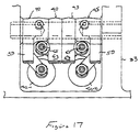
- Figure 17 is a top plan view, in part similar to Figures 1 and 15, and shows yet another embodiment of mechanism employing variable valve actuating mechanism for both valves associated with a single cylinder of the engine.
- Figure 18 is an exploded view, in part similar to Figures 2 and 16, but shows the cam shaft and rocker arms for this embodiment.
- Figure 19 is a top plan view, in part similar to Figures 1, 15 and 17, and shows yet another embodiment of the invention wherein both valves associated with the same cylinder has a variable valve actuating mechanism but, in this embodiment, sharing one of the rocker arms.
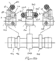
- Figure 20 is an exploded view, in part similar to Figures 2, 16 and 18, showing the cam shaft and rocker arm of this embodiment.
- Figure 21 is a cross-sectional view, in part similar to Figure 3, but shows another type of biasing arrangement for the second rocker arm.
- Figure 22 is a cross-sectional view taken through a cylinder head that utilizes a return arrangement for the second rocker arm as shown in Figure 21, with the associated cylinder bore and remaining valves shown in phantom line.
- Referring now in detail to the drawings and initially to the embodiment of Figures 1-13, a portion of a cylinder head assembly of an internal combustion engine is illustrated and is identified generally by the
reference numeral 31. Only a portion of the engine is illustrated and specifically the cylinder head thereof because the invention deals, as aforenoted, with a valve actuating mechanism for engines. Therefore, when any details of the construction of the engine are not illustrated, they may be considered to be conventional. Those skilled in the art will be able to determine from the following description how the invention can be utilized with a wide variety of engines. - In all of the embodiments illustrated, the depicted engine and
cylinder head 31 are of the four valve cylinder type. This is because the invention has particular utility with multi-valve engines, for reasons which will become apparent. However, the invention can be utilized with engines having any number of valves including only two valves per cylinder or more than two valves in any number. - The
cylinder head assembly 31 includes a maincylinder head member 32 which has an upper surface which carries a bearing andcam carrier 33 and which is closed by acam cover 34. - As best seen in Figures 3-5, each cylinder of the engine is served by a pair of
intake passages 35 that terminate invalve seats 36 which are valved by poppet-type intake valves, indicated generally by thereference numeral 37. Thesevalves 37 havehead portions 38 that cooperate with thevalve seats 36 andstem portions 39 that are slidably supported invalve guides 41 affixed to thecylinder head member 32. - At their upper ends,
keeper retainer assemblies 42 retainspring assemblies 43 that act between thekeeper retainer assemblies 42 and the cylinder head for biasing thevalves 37 to their closed positions, as is well-known in this art. - Referring now primarily to Figures 1 and 2, a cam shaft, indicated generally by the
reference numeral 44, is journaled in thecam carrier 33 by bearing surfaces formed by it and bearing caps which are not illustrated. Thecam shaft 44 has three lobes comprised of a first,center lobe 45, asecond lobe 46, and athird lobe 47. Associated with these lobes 45-47 are first, second and third rocker arms, indicated generally by thereference numerals rocker arms rocker arm shaft 52 that is carried by thecam carrier member 33 in any known manner. - As may be best seen from Figure 1, the
cam lobes cooperating rocker arms valves 37, the keeper retainer of which is indicated by the reference numeral 42-1. Theremaining cam lobe 47 androcker arm 51 are associated with and operate theremaining intake valve 37 and their association is indicated by the reference numeral 42-2, which identifies the keeper retainer of this remaining valve. - The
first rocker arm 48 is a rocker arm which, under all conditions, operates the associated intake valve having a retainer 42-1. Thisrocker arm 48 has afollower portion 59 which is engaged with thecam lobe 45 and which is actuated by it. An actuating portion 61 extends integrally outwardly from the area adjacent thecam follower 59 and carries an adjustingscrew 62 at its outer end which cooperates with the tip of thestem 39 of the associated valve. Thus, this rocker arm generally operates as a conventional rocker arm for the valve actuation during such time as thesecond rocker arm 49 is not coupled to it. This coupling method will be described later. - Referring now primarily to Figures 1-3, the
second rocker arm 49 and its cooperation with thecam lobe 46 will be described. Therocker arm 49 has an outwardly extending arm which forms anintegral follower 63 that is engaged by thecam lobe 46. At this point, it should be noted that thecam lobe 46 is of a larger lift and larger diameter than that of thecam lobe 45. In addition to providing a different lift, thiscam lobe 46 may also be configured to provide slightly different timing through its cooperation with thefirst rocker arm 48. - Adjacent the
follower surface 63, therocker arm 49 is provided with aprotrusion 64 that receives an adjustingscrew 65. This adjustingscrew 65 operates in conjunction with a coupling mechanism to, at times, control the operation of therocker arm 48. That mechanism will be described very shortly. - In order to maintain the
rocker follower surface 63 in engagement with thecam lobe 46, a biasing arrangement shown in Figure 3 is provided. As seen in this Figure, aspring carrier 66 is affixed to thecam carrier 33 in a known manner. Thespring carrier 66 is provided with a plurality of pockets, one for eachrocker arm 49. A spring arrangement, indicated by thereference numeral 67, is supported in each of these pockets. - The spring arrangement includes an
outer cylinder member 68 which defines a bore in which a sliding biasingmember 69 is provided. The sliding biasingmember 69 is biased by acoil compression spring 71 into engagement with afurther follower surface 72 formed on a portion of therocker arm 49 that extends in somewhat diametrical opposition to the portion that forms thefollower surface 63. Thus, thespring 71 acting through the biasingmember 69 androcker arm surface 72 will maintain therocker arm follower 63 in engagement with thecam lobe 46. - The mechanism for selectively coupling the
rocker arm 49 to operate therocker arm 48 will now be described by particular reference to Figures 4-13. Figures 4 and 5 show this coupling mechanism, which is indicated generally by thereference numeral 73, in the disengaged condition so that therocker arm 48 operates without any control or interference from therocker arm 49. Under this condition, thecam lobe 45 androcker arm 48 control the degree of maximum opening and timing of opening of thevalve 37 with the fully-opened position being shown in Figure 5. - The
rocker arm 48 has aboss portion 74 that is formed adjacent itsfollower surface 59 but below it. Acylindrical bore 75 is formed in thisboss 74. A coupling plunger member, having a configuration shown in Figures 8-10 and indicated generally by thereference numeral 76, is slidably supported within this bore. Thiscoupling plunger member 76 has a head ortop portion 77 which is positioned to be and is engaged during the running of the engine by thescrew 65. - As may be best seen in Figure 11, the lower end of the
bore 74 is partially closed by acap 78 which forms an engagement for a biasingspring 79 that acts on the lower end of thecoupling plunger member 76. Thisspring 79 keeps thecoupling plunger member 76 and specifically itssurface 77 in constant engagement with the adjustingscrew 65. It should be apparent, however, that if desired, some clearance may be maintained in this gap depending upon how the valve operation is to be accomplished. Also in some views the position of theplunger member 76 in the bore may not be the true position depending upon the lift characteristics of therespective cams - The
coupling plunger member 76 is formed with abore 81 that extends from aflat surface 82 formed in a side thereof by a machinedrecess 83. Received within thebore 81 is a return spring arrangement that is comprised of a pair ofend caps coil compression spring 87. - In the uncoupled state when only the
cam 45 is operating thevalve 37, thiscompression spring 87 causes the retainingmember 86 to be urged to a position where a flat surface of it is coextensive with thesurface 82. Under this condition thesurface 82 is engaged by aslidable locking member 88. - The locking
member 88 is slidably supported within abore 89 that extends through therocker arm 48 below its journal on therocker arm shaft 51. The outer end of this bore 89 is closed by a closure plug 91 and in the uncoupled state, the lockingmember 88 is abuttingly engaged with this closure plug 91. - The cooperation of the locking
member 88 with the side of thesurface 82 will permit reciprocation of thecoupling plunger member 76 in thebore 75 between the position shown in Figure 4 which represents the closed condition and the position shown in Figure 6 which shows the condition when theintake valve 37 is opened to its maximum lift during the time when thecam lobe 45 is operating therocker arm 48 so as to control the timing and lift of thevalve 37. Rotation of theplunger member 76 in thebore 75 is, however, precluded by this coaction. - When the
cam lobe 46 operates therocker arm 49 to begin its lift, then thecoupling plunger member 76 will be driven downwardly in thebore 75 as shown in Figure 6. Under this condition, no additional movement of therocker arm 48 will occur and thus there is lost motion under this operation. - It should be noted that in the retracted position of the locking
member 88, agap 92 is provided between it and the end closure 91. This gap communicates with anoil control passage 93 that extends through therocker arm shaft 51 androcker arm 48. Therocker arm shaft 51 is hollow and hydraulic fluid pressure may be exerted selectively through thispassage 73 to thearea 92 in accordance with a desired control strategy. One such strategy will be described later by reference to the embodiment of Figure 14. - When this
passage 93 is pressurized, as shown in Figures 11 and 12, the lockingplunger 83, when it registers with thebore 81, will act on theretainer member 86 and force it inwardly and compress thespring 87. At this time, therocker arms rocker arm 49, because of its greater lift and timing, will actually control the opening degree of the valve so as to provide a greater lift under this coupled condition as clearly shown in Figure 13. By comparing Figure 13 with Figure 5, this greater lift condition can be readily appreciated. - When the hydraulic pressure in the
passage 93 andarea 92 is relieved, thespring 87 will urge the lockingplunger 88 back to its disengaged position as shown in Figures 4-7. - Referring back to Figures 1 and 2, it will be seen that the
rocker arm 51 andcam lobe 47 that operate the remaining intake valve which does not have its lift varied in this embodiment. Therocker arm 51 has afollower surface 94 that is engaged by thecam lobe 47. An adjustingscrew 95 carried at the tip of this rocker arm cooperates with the stem of this valve to operate it in a normal manner. Varying types of lift arrangements may be employed and different lift ratios and/or valve timing between the non-variable actuated valve and the variable actuated valve. That is the lift and/or timing of the valve operated by thecam 47 may be the same as that provided by either of thecams - Figure 14 is a view that shows one way in which this mechanism may operate. This view shows the induction system schematically and it now will be described by reference to that Figure. In this Figure, the normally or non-variably actuated valve is indicated by the reference numeral 37-2, while the variably actuated valve is indicated by the reference numeral 37-1. The
intake passages 35 associated therewith have also been indicated by the same suffixes, i.e., 35-2 and 35-1. - In accordance with this embodiment, an air inlet device, indicated by the reference numeral 101, draws atmospheric air through an
inlet opening 102 in which a manually actuated throttle control valve 103 is positioned. The air inlet device 101 forms aplenum chamber 104 that communicates with the runners 35-1 and 35-2 of each cylinder. - A
control valve 105 is provided in the runner 35-2 and is operated by a servo motor 106 under the control of an ECU, indicated generally by thereference numeral 107. - In this embodiment, the intake valve 37-1 and its operation is adjusted to optimize primarily the low and mid-range performance of the engine. Thus, the
cam lobe 45 androcker arm 48 can be tailored for optimum performance under low-speed and low-mid range running. Thecam lobe 46 androcker arm 49 are coupled for a higher range of operation and may provide a substantially greater lift so as to improve the performance under higher speeds and loads. - Thus, the control strategy for the ECU is to sense throttle position or load and engine speed and be mapped so as to activate the servo motor 106 and maintain the
throttle valve 105 in a closed position during low-speed and low-to-medium mid-range running. - As the speed and load increase, however, then the ECU effects opening of the
control valve 105 by the servo motor 106. Thus, the engine can provide very good performance under a wide variety of speeds and loads due to the use of the variable valve actuating mechanism and thecontrol valve 105. - The foregoing example is only one type of strategy that can be employed and the maximum lift for the valves 37-1 and 37-2 can be either the same or different depending upon the particular engine and tuning arrangement selected, as already noted.
- In order to permit a compact assembly, obviously the adjusting
screw 65 must be configured in relation to the cam lobes and specifically thecam lobe 45, so as to not present any interference. - Figures 15 and 16 show another embodiment of the invention wherein both of the intake valves 37-1 and 37-2 are provided with a variable valve actuating mechanism. In this particular embodiment, the cam shaft is provided with, in addition to, the
lobes additional lobes rocker arms - It should be noted that the
rocker arms rocker arms 48 to be positioned next to each other and the other two rocker arms to be spaced more widely. With this type of arrangement, as shown, the initial lift for the valve 37-2 is less than that of the valve 37-1 but the maximum lift provided by thecam lobes - Figures 17 and 18 show yet another embodiment. In this embodiment, the rocker arms are reversed from the position utilized in Figures 15 and 16. That is, the direct
actuating rocker arms 48 are disposed outwardly of the indirectacting rocker arms 49. Again, varying lift arrangements may be employed. As illustrated in this embodiment, the initial lift of the valve 37-1 is substantially greater than that of the remaining valve 37-2 while the maximum lift also is larger but only slightly larger as indicated by the respective cam lobe portions. - In all of the embodiments thus far described, those valves that have had adjustable valve actuation have had associated with them their own first and second rocker arms and first and second cam lobes. Figures 19 and 20 show another embodiment wherein the second rocker arms for the two valves are integrated into a single rocker arm. Since that is the only difference between this embodiment and that shown in Figures 17 and 18, components which are the same are identified by the same reference numerals and will not be described again, except insofar as is necessary to understand the construction and operation of this embodiment.
- In this embodiment, a single
second rocker arm 201 for each of the valves 37-1 and 37-2 is provided . Thisrocker arm 201 has a single follower surface 202 that is engaged by asingle cam lobe 203. This rocker arm has a pair ofbosses respective adjusting screw adjacent rocker arms 48, in the manner that has already been described. Thus, with this construction, the arrangement can be further simplified. However, the operation of thesecond rocker arm 201 on each valve then must be the same. Different lift characteristics can be provided for the operation of the valves 37-1 and 37-2 and in this embodiment the lift of 37-1 is greater than that of 37-2 before therocker arm 201 actuates both valves. - Figures 21 and 22 show both the incorporation of the variable valve actuating mechanism for all valves of the engine and also shows a different biassing arrangement for the second rocker arms. Since this is the only main difference, components which are the same or substantially the same have been identified by the same reference numerals.
- In this embodiment, the
second rocker arms 48 have, on the opposite side from their follower surfaces 59, a protrudingportion 251 that is engaged by a spring return mechanism which is in essence the same as that employed in and shown in detail in Figure 3. However, thisreturn mechanism 67 is mounted directly in thecylinder head member 32 rather than on thecam carrier 33. In all other regards, this embodiment is the same and thus, further description of it is not believed to be necessary to permit those skilled in the art to practice the invention. - From the foregoing description, it should be readily apparent to those skilled in the art that the various embodiments disclosed provide a very effective and compact arrangement for achieving variable valve actuation.
Claims (20)
- A valve operating mechanism for operating a single poppet valve (37) of an engine through cooperation with the stem (39) thereof, said valve operating mechanism being comprised of a single cam shaft (44) having a pair of adjacent cams (45, 46), a pair of adjacent pivotally supported rocker arms (48, 49), each of said rocker arms being operated by a respective one of said cams, a first of said rocker arms (48) having an operating portion for direct engagement with the valve stem (39) for operating the valve (37) directly, and means (73) for selectively coupling the second of said rocker arms (49) to said first rocker arm (48) for effecting actuation of the valve (37) therefrom through said first rocker arm (48) by the cam (46) associated with said second rocker arm (49) comprising actuating means (65) carried by the second rocker arm (49) and engageable with coupling means carried by the first rocker arm (48) for actuating the first rocker arm, said coupling means comprising a plunger (76) slidably supported within a bore (75) formed in the first rocker arm (48) and which plunger (76) is engaged by the actuating means (65) of the second rocker arm (49), characterized by a hydraulically operated pin slidably supported in the first rocker arm (48) and engageable with a bore (81) formed in the plunger (76) for locking the plunger (76) against sliding movement in the bore (81), and a hollow rocker arm shaft (52), wherein hydraulic pressure is transmitted through the rocker arm shaft to the pin (88).
- A valve operating mechanism as set forth in Claim 1, wherein both of the rocker arms (48, 49) are journaled on the same rocker arm shaft (52).
- A valve operating mechanism as set forth in Claim 1 or 2, wherein the first and second cams (45, 46) and first and second rocker arms (48, 49) provide a different lift for the actuated valve (37).
- A valve operating mechanism as set forth in Claim 3, wherein the lift provided by the second cam (46) and second rocker arm (49) is greater than that provided by the first cam (45) and the first rocker arm (48).
- A valve operating mechanism as set forth in Claim 2, wherein the valve (37) has a spring (79) that is associated with it for maintaining the first rocker arm (48) in engagement with the first cam (45) and further including a separate biasing spring (71) for urging the second rocker arm (49) into engagement with the second cam (46).
- A valve operating mechanism as set forth in Claim 5, wherein the second spring (71) is engaged with an arm (72) of the second rocker arm (49) that is spaced from its actuating portion (63) and which spring (71) bears against the engine body (32).
- A valve operating mechanism as set forth in any of Claims 1 to 6, wherein there is provided a second poppet valve (37-2) for serving the same combustion chamber of the engine and wherein the second poppet valve (37-2) is adjacent the first mentioned poppet valve (37-1).
- A valve operating mechanism as set forth in Claim 7, wherein both poppet valves (37-1, 37-2) communicate with the combustion chamber.
- A valve operating mechanism as set forth in Claim 8, wherein the second poppet valve (37-2) is operated by a third cam (47) through a third rocker arm (51).
- A valve operating mechanism as set forth in Claim 9, wherein all of the rocker arms (48, 49, 51) are supported on the same rocker arm shaft (52).
- A valve operating mechanism as set forth in Claim 10, the valves (37-1, 37-2) are both intake valves.
- A valve operating mechanism as set forth in Claim 11, wherein the first valve (37-1) is operated with a low lift by the first cam (45) and the first rocker arm (48) and a higher lift by the second cam (46) and the second rocker arm (49) acting through the first rocker arm (48) and wherein the third cam (47) and the third rocker arm (51) provide a lift for the second valve (37-2) that is higher than that of the first cam (45) and the first rocker arm (48) on the first valve (37-1).
- A valve operating mechanism as set forth in Claim 12, wherein separate intake passages (35-1, 35-2) serve the intake valves (37-1, 37-2) and further including a control valve (105) in the intake passage (35-2) serving the second valve (37-2) controlled in response to engine running conditions and opened under only high speed, high load conditions.
- A valve operating mechanism as set forth in Claim 7, wherein the second valve (37-2) is operated by first and second rocker arms (48, 49) each cooperating with a respective cam lobe (45, 46) to provide a different lift and further including means for selectively coupling the first and second rocker arms (48, 49) associated with the second valve (37-2) with each other for varying the lift of the second valve (37-2).
- A valve operating mechanism as set forth in Claim 14, wherein the first rocker arms (48, 48) for the two valves (37-1, 37-2) are disposed adjacent each other on the rocker arm shaft (52).
- A valve operating mechanism as set forth in Claim 14 or 15, wherein the second rocker arms (49, 49) are disposed adjacent each other on the same rocker arm shaft (52).
- A valve operating mechanism as set forth in Claim 16, wherein the lift provided by the first cam (45) and first rocker arm (48) of one of the valves (37-1, 37-2) is different from that provided by the first cam (45) and first rocker arm (48) of the other valve (37-2, 37-1).
- A valve operating mechanism as set forth in any of Claims 14 to 17, wherein one of the rocker arms for each of the valves is a common rocker arm (201) that is capable of actuating both of the valves (37-1, 37-2).
- A valve operating mechanism as set forth in Claim 18, wherein the one rocker arm (201) is the second rocker arm.
- A valve operating mechanism as set forth in Claim 19, wherein the one rocker arm (201) cooperates with a single second cam (203).
Applications Claiming Priority (9)
| Application Number | Priority Date | Filing Date | Title |
|---|---|---|---|
| JP26607196 | 1996-10-07 | ||
| JP26608096 | 1996-10-07 | ||
| JP26608096 | 1996-10-07 | ||
| JP26607196 | 1996-10-07 | ||
| JP266080/96 | 1996-10-07 | ||
| JP266071/96 | 1996-10-07 | ||
| JP277692/96 | 1996-10-21 | ||
| JP8277692A JPH10121928A (en) | 1996-10-21 | 1996-10-21 | Valve system for internal combustion engine |
| JP27769296 | 1996-10-21 |
Publications (2)
| Publication Number | Publication Date |
|---|---|
| EP0834647A1 EP0834647A1 (en) | 1998-04-08 |
| EP0834647B1 true EP0834647B1 (en) | 2002-07-03 |
Family
ID=27335430
Family Applications (1)
| Application Number | Title | Priority Date | Filing Date |
|---|---|---|---|
| EP97117316A Expired - Lifetime EP0834647B1 (en) | 1996-10-07 | 1997-10-07 | Engine valve actuating system |
Country Status (3)
| Country | Link |
|---|---|
| US (1) | US5924396A (en) |
| EP (1) | EP0834647B1 (en) |
| DE (1) | DE69713702T2 (en) |
Families Citing this family (13)
| Publication number | Priority date | Publication date | Assignee | Title |
|---|---|---|---|---|
| US6053135A (en) * | 1997-10-07 | 2000-04-25 | Yamaha Hatsudoki Kabushiki Kaisha | Variable valve timing mechanism |
| EP0908604B1 (en) | 1997-10-07 | 2002-05-15 | Yamaha Hatsudoki Kabushiki Kaisha | Variable valve timing mechanism |
| US6092497A (en) * | 1997-10-30 | 2000-07-25 | Eaton Corporation | Electromechanical latching rocker arm valve deactivator |
| US6705264B2 (en) | 1998-12-24 | 2004-03-16 | Yamaha Marine Kabushiki Kaisha | Valve control for outboard motor engine |
| US6418904B2 (en) | 2000-04-03 | 2002-07-16 | Daimlerchrysler Corporation | Pulse drive valve deactivator |
| JP2001342919A (en) | 2000-05-31 | 2001-12-14 | Sanshin Ind Co Ltd | Four-cycle engine of outboard motor |
| US6910450B2 (en) | 2000-05-31 | 2005-06-28 | Yamaha Marine Kabushiki Kaisha | Variable valve timing structure for outboard motor engine |
| JP2001342812A (en) | 2000-05-31 | 2001-12-14 | Sanshin Ind Co Ltd | Four cycle engine for outboard motor |
| GB2395521A (en) * | 2002-11-23 | 2004-05-26 | Mechadyne Plc | Engine with variable valve mechanism |
| US7040265B2 (en) * | 2003-06-03 | 2006-05-09 | Daimlerchrysler Corporation | Multiple displacement system for an engine |
| US20040244751A1 (en) * | 2003-06-03 | 2004-12-09 | Falkowski Alan G. | Deactivating valve lifter |
| CN100334332C (en) * | 2003-06-17 | 2007-08-29 | 本田技研工业株式会社 | Valve train for internal combustion engine |
| DE112015001759T5 (en) * | 2014-05-15 | 2017-03-09 | Borgwarner Inc. | Locking solenoid for engine control |
Family Cites Families (15)
| Publication number | Priority date | Publication date | Assignee | Title |
|---|---|---|---|---|
| DE3239941A1 (en) * | 1982-10-28 | 1984-05-03 | Volkswagenwerk Ag, 3180 Wolfsburg | Device for switching off the valve mechanism of an internal combustion engine |
| US4726332A (en) * | 1985-04-26 | 1988-02-23 | Mazda Motor Corporation | Variable valve mechanism for internal combustion engines |
| JPS61175206A (en) * | 1985-07-23 | 1986-08-06 | Mazda Motor Corp | Valve operating device in engine |
| US4887563A (en) * | 1986-10-16 | 1989-12-19 | Honda Giken Kogyo Kabushiki Kaisha | Valve operating apparatus for an internal combustion engine |
| DE3814835A1 (en) * | 1987-05-20 | 1988-12-01 | Volkswagen Ag | Internal combustion engine with at least two inlet valves per combustion chamber |
| JP2779429B2 (en) * | 1989-09-06 | 1998-07-23 | 株式会社オティックス | Variable valve timing / lift amount mechanism for valve train |
| US5251586A (en) * | 1991-03-29 | 1993-10-12 | Fuji Jukogyo Kabushiki Kaisha | Valve mechanism for an internal combustion engine |
| US5239952A (en) * | 1991-11-08 | 1993-08-31 | Atsugi Unisia Corporation | Valve actuating apparatus |
| JP2809005B2 (en) * | 1992-09-17 | 1998-10-08 | 日産自動車株式会社 | Variable valve train for internal combustion engines |
| JP2762216B2 (en) * | 1993-09-28 | 1998-06-04 | 本田技研工業株式会社 | Internal combustion engine |
| JP2890236B2 (en) * | 1994-02-28 | 1999-05-10 | 本田技研工業株式会社 | Valve operating control device for internal combustion engine |
| JPH0874533A (en) * | 1994-09-02 | 1996-03-19 | Nissan Motor Co Ltd | Valve system of internal combustion engine |
| JP3319896B2 (en) * | 1994-12-21 | 2002-09-03 | 株式会社ユニシアジェックス | Engine Valve Actuator |
| JP3319920B2 (en) * | 1995-10-12 | 2002-09-03 | 株式会社ユニシアジェックス | Engine Valve Actuator |
| US5651336A (en) * | 1995-12-26 | 1997-07-29 | Chrysler Corporation | Variable valve timing and lift mechanism |
-
1997
- 1997-10-07 EP EP97117316A patent/EP0834647B1/en not_active Expired - Lifetime
- 1997-10-07 US US08/946,047 patent/US5924396A/en not_active Expired - Fee Related
- 1997-10-07 DE DE69713702T patent/DE69713702T2/en not_active Expired - Lifetime
Also Published As
| Publication number | Publication date |
|---|---|
| DE69713702D1 (en) | 2002-08-08 |
| US5924396A (en) | 1999-07-20 |
| DE69713702T2 (en) | 2003-03-13 |
| EP0834647A1 (en) | 1998-04-08 |
Similar Documents
| Publication | Publication Date | Title |
|---|---|---|
| CA1274132A (en) | Valve operating mechanism for internal combustion engine | |
| EP0420159B1 (en) | Variable valve timing rocker arm arrangement for internal combustion engine | |
| EP0703351B1 (en) | Valve operating system for multi-cylinder internal combustion engine | |
| US6354254B1 (en) | Exhaust and intake rocker arm assemblies for modifying valve lift and timing during positive power | |
| US4790274A (en) | Valve operating mechanism for internal combustion engine | |
| US5785017A (en) | Variable valve timing mechanism | |
| CA1284069C (en) | Valve operating mechanism for internal combustion engine | |
| US6343581B2 (en) | Variable valve timing and lift structure for four cycle engine | |
| EP0834647B1 (en) | Engine valve actuating system | |
| US5046462A (en) | Rocker arm arrangement for variable valve timing type internal combustion engine valve train | |
| JP2000045738A (en) | Compression engine brake device | |
| US5752479A (en) | Valve operating mechanism for 4-cycle engine | |
| US4741297A (en) | Valve operating mechanism for internal combustion engine | |
| US6053135A (en) | Variable valve timing mechanism | |
| US4572117A (en) | Valve arrangement for an internal combustion engine | |
| US6481398B2 (en) | High-low speed range switching type valve mechanism for internal combustion engine | |
| EP0908604B1 (en) | Variable valve timing mechanism | |
| JPH0346642B2 (en) | ||
| JPH04284109A (en) | Valve operating device of engine | |
| US6964252B2 (en) | Valve lifter for internal combustion engine | |
| JPH05312014A (en) | Variable valve system of internal combustion engine | |
| JPH0239608B2 (en) | ||
| JP2547143Y2 (en) | Engine Valve Actuator | |
| JP2519337Y2 (en) | Valve operating device for multi-cylinder engine | |
| JPH0347408B2 (en) |
Legal Events
| Date | Code | Title | Description |
|---|---|---|---|
| PUAI | Public reference made under article 153(3) epc to a published international application that has entered the european phase |
Free format text: ORIGINAL CODE: 0009012 |
|
| AK | Designated contracting states |
Kind code of ref document: A1 Designated state(s): DE FR GB IT |
|
| AX | Request for extension of the european patent |
Free format text: AL;LT;LV;RO;SI |
|
| 17P | Request for examination filed |
Effective date: 19981007 |
|
| AKX | Designation fees paid |
Free format text: DE FR GB IT |
|
| RBV | Designated contracting states (corrected) |
Designated state(s): DE FR GB IT |
|
| 17Q | First examination report despatched |
Effective date: 19990610 |
|
| GRAG | Despatch of communication of intention to grant |
Free format text: ORIGINAL CODE: EPIDOS AGRA |
|
| GRAG | Despatch of communication of intention to grant |
Free format text: ORIGINAL CODE: EPIDOS AGRA |
|
| GRAG | Despatch of communication of intention to grant |
Free format text: ORIGINAL CODE: EPIDOS AGRA |
|
| GRAH | Despatch of communication of intention to grant a patent |
Free format text: ORIGINAL CODE: EPIDOS IGRA |
|
| GRAH | Despatch of communication of intention to grant a patent |
Free format text: ORIGINAL CODE: EPIDOS IGRA |
|
| GRAA | (expected) grant |
Free format text: ORIGINAL CODE: 0009210 |
|
| AK | Designated contracting states |
Kind code of ref document: B1 Designated state(s): DE FR GB IT |
|
| REF | Corresponds to: |
Ref document number: 69713702 Country of ref document: DE Date of ref document: 20020808 |
|
| ET | Fr: translation filed | ||
| PLBE | No opposition filed within time limit |
Free format text: ORIGINAL CODE: 0009261 |
|
| STAA | Information on the status of an ep patent application or granted ep patent |
Free format text: STATUS: NO OPPOSITION FILED WITHIN TIME LIMIT |
|
| 26N | No opposition filed |
Effective date: 20030404 |
|
| PGFP | Annual fee paid to national office [announced via postgrant information from national office to epo] |
Ref country code: GB Payment date: 20051005 Year of fee payment: 9 |
|
| PGFP | Annual fee paid to national office [announced via postgrant information from national office to epo] |
Ref country code: IT Payment date: 20061031 Year of fee payment: 10 |
|
| GBPC | Gb: european patent ceased through non-payment of renewal fee |
Effective date: 20061007 |
|
| PG25 | Lapsed in a contracting state [announced via postgrant information from national office to epo] |
Ref country code: GB Free format text: LAPSE BECAUSE OF NON-PAYMENT OF DUE FEES Effective date: 20061007 |
|
| PGFP | Annual fee paid to national office [announced via postgrant information from national office to epo] |
Ref country code: FR Payment date: 20070424 Year of fee payment: 10 |
|
| REG | Reference to a national code |
Ref country code: FR Ref legal event code: ST Effective date: 20080630 |
|
| PG25 | Lapsed in a contracting state [announced via postgrant information from national office to epo] |
Ref country code: FR Free format text: LAPSE BECAUSE OF NON-PAYMENT OF DUE FEES Effective date: 20071031 |
|
| PG25 | Lapsed in a contracting state [announced via postgrant information from national office to epo] |
Ref country code: IT Free format text: LAPSE BECAUSE OF NON-PAYMENT OF DUE FEES Effective date: 20071007 |
|
| PGFP | Annual fee paid to national office [announced via postgrant information from national office to epo] |
Ref country code: DE Payment date: 20100929 Year of fee payment: 14 |
|
| PG25 | Lapsed in a contracting state [announced via postgrant information from national office to epo] |
Ref country code: DE Free format text: LAPSE BECAUSE OF NON-PAYMENT OF DUE FEES Effective date: 20120501 |
|
| REG | Reference to a national code |
Ref country code: DE Ref legal event code: R119 Ref document number: 69713702 Country of ref document: DE Effective date: 20120501 |