EP1031382A2 - Sprinkler with adjustable water spray jets - Google Patents
Sprinkler with adjustable water spray jets Download PDFInfo
- Publication number
- EP1031382A2 EP1031382A2 EP00101308A EP00101308A EP1031382A2 EP 1031382 A2 EP1031382 A2 EP 1031382A2 EP 00101308 A EP00101308 A EP 00101308A EP 00101308 A EP00101308 A EP 00101308A EP 1031382 A2 EP1031382 A2 EP 1031382A2
- Authority
- EP
- European Patent Office
- Prior art keywords
- pipe
- water
- sprinkler
- drive assembly
- water spray
- Prior art date
- Legal status (The legal status is an assumption and is not a legal conclusion. Google has not performed a legal analysis and makes no representation as to the accuracy of the status listed.)
- Granted
Links
Images


Classifications
-
- B—PERFORMING OPERATIONS; TRANSPORTING
- B05—SPRAYING OR ATOMISING IN GENERAL; APPLYING FLUENT MATERIALS TO SURFACES, IN GENERAL
- B05B—SPRAYING APPARATUS; ATOMISING APPARATUS; NOZZLES
- B05B3/00—Spraying or sprinkling apparatus with moving outlet elements or moving deflecting elements
- B05B3/02—Spraying or sprinkling apparatus with moving outlet elements or moving deflecting elements with rotating elements
- B05B3/04—Spraying or sprinkling apparatus with moving outlet elements or moving deflecting elements with rotating elements driven by the liquid or other fluent material discharged, e.g. the liquid actuating a motor before passing to the outlet
- B05B3/0409—Spraying or sprinkling apparatus with moving outlet elements or moving deflecting elements with rotating elements driven by the liquid or other fluent material discharged, e.g. the liquid actuating a motor before passing to the outlet with moving, e.g. rotating, outlet elements
- B05B3/0418—Spraying or sprinkling apparatus with moving outlet elements or moving deflecting elements with rotating elements driven by the liquid or other fluent material discharged, e.g. the liquid actuating a motor before passing to the outlet with moving, e.g. rotating, outlet elements comprising a liquid driven rotor, e.g. a turbine
- B05B3/0422—Spraying or sprinkling apparatus with moving outlet elements or moving deflecting elements with rotating elements driven by the liquid or other fluent material discharged, e.g. the liquid actuating a motor before passing to the outlet with moving, e.g. rotating, outlet elements comprising a liquid driven rotor, e.g. a turbine with rotating outlet elements
- B05B3/0431—Spraying or sprinkling apparatus with moving outlet elements or moving deflecting elements with rotating elements driven by the liquid or other fluent material discharged, e.g. the liquid actuating a motor before passing to the outlet with moving, e.g. rotating, outlet elements comprising a liquid driven rotor, e.g. a turbine with rotating outlet elements the rotative movement of the outlet elements being reversible
- B05B3/044—Tubular elements holding several outlets, e.g. apertured tubes, oscillating about an axis substantially parallel to the tubular element
Definitions
- the present invention refers to a sprinkler provided with adjustable water spray jets, adapted in particular for use in gardening applications to water cultivated land, such as lawns or gardens, in which there may grow also trees.
- sprinklers There are many kinds of sprinklers currently known in the art, ie. fixed, rotating, pulsating and oscillating sprinklers, wherein they differ from each other on the basis of the type of water jets that they produce. However, all of them are substantially constituted by an element which, duly provided with one or more nozzles, is adapted to issue water that is supplied to it through a water turbine from a water supply source to which the same sprinkler is connected via a flexible hose.
- the sprinklers themselves can either be fixed into the ground by means of a proper spike or be mounted on a base framework that simply rests on the ground.
- Fixed-jet sprinklers are the simplest ones and are capable of watering surfaces that may be variously shaped, but must not be too large in their size, by selecting or replacing the spray nozzles correspondingly.
- Rotary sprinklers along with pulsating ones, are more complicated in their construction and operation owing to the need arising for a movement to be imparted to the spray jets, and therefore the heads or arms that carry the spray nozzles. Such a movement is generally brought about, through the provision of a transmission mechanism, by the same water turbine that supplies the spray nozzles.
- These types of sprinklers are adapted to water circular surfaces, either completely or pardally, which are generally larger than the ones that can usually be irrigated with the afore cited fixed sprinklers.
- a sprinkler provided with adjustable water spray jets which comprises, as recited in the appended claim 1, a base framework for it to rest on the ground, said framework supporting a pipe provided with water spray nozzles and a turbine-type drive assembly, which are connected to a water supply source, in which between said turbine-type drive assembly and the spray pipe there is installed a device for adjusting the flow rate of the supply water.
- a sprinkler according to the present invention is illustrated in particular in Figures 1 and 2.
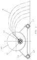
- the sprinkler is substantially constituted by: a framework 10, which enables the sprinkler to rest on the ground; a rectilinear pipe 11, provided with a plurality of nozzles 12, which is mounted in a fixed position with respect to said framework 10; and a hydraulic turbine-type drive assembly 13, secured to the framework 10, which is provided with a water inlet connector 14 ensuring the water supply to the spray pipe 11.
- the support framework 10 is of a traditional type, comprising two appropriately shaped end portions 15 and 16, in which the first one is adapted to allow for the mounting of the drive assembly 13 and the second one is adapted to accommodate the extremity of the spray pipe 11 that is opposed to the one connecting the latter to said drive assembly 13. Said end portions 15 and 16 are joined and connected together through tubular members 17 that are fined into appropriate receptacles provided in the same end portions. The extremity of the spray pipe 11 that is opposite to the one connecting the latter with the drive assembly 13 is normally shut by a cap 30.
- the drive assembly 13 enclosed in a box-like casing, comprises a horizontal-axis water turbine 18 that is operated by the water under pressure that flows in through the water inlet connector 14.
- the latter is adapted to be connected, for instance, to the water supply source by means of a flexible hose (not shown).
- This water inlet connector 14 extends into the drive assembly 13 and has an aperture 19 for the water to flow therethrough, in which said aperture is arranged in such a manner as to enable the water jet to hit the blades of the turbine 18 radially.
- a threaded reel 21 On the shaft 20 of the water turbine 18 there is provided a threaded reel 21 that is rotatably engaged by a gear 22 which is firmly joined to an extremity of a cylindrical pipe 23.
- the latter is capable of rotating inside of a cylindrical housing 24, which is firmly associated to the casing accommodating the drive assembly 13 and extends coaxially inside the water spray pipe 11.
- an aperture 25 In the cylindrical wall of the pipe 23 there is provided an aperture 25, preferably in an elongated oval shape, having its major axis parallel to the central axis of the pipe 23.
- an aperture 26 which has a progressively variable cross-section.
- the two portions of the pipe 23 and the housing 24, which are so provided with said aperture 25 and said apertures 26 (the latter are in the number of two, in this case), respectively, are shown in Figure 3 as developed on a plane and in a side-by-side arrangement.
- the apertures 26 have preferably a triangular shape and are arranged with a bisector B-B extending orthogonally to the major longitudinal axis L-L of the aperture 25.
- the water flow rate varies progressively from a minimum to a maximum value.
- the water flow rate is at a minimum when the aperture 25 of the pipe 23 is located in front of the closed, ie. solid wall of the housing 24.
- the water flow rate is on the contrary at a maximum when said aperture 25 is located in correspondence of the base of the triangular aperture 26 opposite to the vertex V.
- the term "sprinkler” shall not be understood as only indicating a device intended to water portions of ground, but rather any device issuing one or more water jets, such as for instance the jets of a fountain. Even in a case like this one, in fact, it may be of advantage to apply a flow-rate regulator for the jets.
- the constant cross-section aperture 25 and the varying cross-section aperture 26 can exchange their position in the rotating pipe 23 and the fixed housing 24, respectively, since this would anyway produce as a result a variation in the flow-rate of the jets issuing from the sprinkler.
- the sprinkler When stating that the sprinkler is a "fixed” one, it is meant that it remains in the same position during its operation; however, it can be easily appreciated that the water spray pipe 11 may be mounted in a different angular position, by rotating it about its own longitudinal axis A-A ( Figure 2), depending on the maximum flow-rate that is actually required for the jets G.
- This adjustment of the inclination, or slope, of the jets issuing from the nozzles 12 is usually performed when the sprinkler is not being supplied with water. However, it can advantageously be performed when the sprinkler is regularly operating, as well.
- the sprinkler generates unidirectional jets G (see Figure 1), so that the user can move near the sprinkler by approaching it on the opposite side of the jets, in order to adjust it without getting wet.
- a particular variant thereof which does not depart from the scope of the present invention, is constituted by the possibility for a double sprinkler to be easily provided, in that two water spray pipes 11 are mounted in a parallel, side-by-side arrangement, said two pipes being able to be supplied by respective water-supply arrangements 22-26 driven by the same drive assembly constituted by the turbine 18, the shaft 20 and the reel 21.
Abstract
Description
- The present invention refers to a sprinkler provided with adjustable water spray jets, adapted in particular for use in gardening applications to water cultivated land, such as lawns or gardens, in which there may grow also trees.
- There are many kinds of sprinklers currently known in the art, ie. fixed, rotating, pulsating and oscillating sprinklers, wherein they differ from each other on the basis of the type of water jets that they produce. However, all of them are substantially constituted by an element which, duly provided with one or more nozzles, is adapted to issue water that is supplied to it through a water turbine from a water supply source to which the same sprinkler is connected via a flexible hose. The sprinklers themselves can either be fixed into the ground by means of a proper spike or be mounted on a base framework that simply rests on the ground.
- Fixed-jet sprinklers are the simplest ones and are capable of watering surfaces that may be variously shaped, but must not be too large in their size, by selecting or replacing the spray nozzles correspondingly.
- Rotary sprinklers, along with pulsating ones, are more complicated in their construction and operation owing to the need arising for a movement to be imparted to the spray jets, and therefore the heads or arms that carry the spray nozzles. Such a movement is generally brought about, through the provision of a transmission mechanism, by the same water turbine that supplies the spray nozzles. These types of sprinklers are adapted to water circular surfaces, either completely or pardally, which are generally larger than the ones that can usually be irrigated with the afore cited fixed sprinklers.
- Oscillating sprinklers are substantially constituted by a horizontal pipe provided with variously oriented perforations or nozzles, mounted on a support framework and rotatably driven alternatingly, ie. according to a reversing pattern, about a longitudinal axis by a water turbine. In the drive gear box containing the water turbine there are provided mechanical control means enabling the surface to be watered to be properly delimited by setting the oscillation angle of the spray pipe accordingly. Further mechanical control means may be provided inside the oscillating pipe to the purpose of enabling the surface to be watered to be adjusted, ie. set, by means of a partialization or throttling of the water spray jets.
- Examples of oscillating sprinklers are described in US-A-3 175 770, US-A-3 567 122 and EP-A-0363717. To bring about the oscillating movement of the water spray pipe, this kind of sprinklers requires a driving mechanism that is rather complicated from a construction point of view, as well as sensitive and delicate from an operational point of view. A further complication is added by the fact that the water spray pipe is out-of-axis with respect to the axis of the drive assembly and the need arises for an external crank to be provided to connect these two elements to each other.
- Examples of oscillating sprinklers provided with such a jet partialization or throttling feature for varying the surface of ground to be watered are described in DE-A-3119094 and EP-A-0394653. These sprinklers are provided with hand-operated control means to selectively supply only part of the nozzles of the oscillating spray pipe. Therefore, they substantially have the same drawbacks as the sprinklers of the above cited type, with the further complication, in this case, of a hand-operated control element that is not effective in doing away with the problem of the selection of the ground surface to be watered to any satisfactory extent.
- Moreover, the adjustment of the spray jets usually requires for the water supply to be temporarily shut off in order to prevent the user from getting wet when approaching the sprinkler for the necessary action. Now, such a handling can turn out as being particularly awkward and disadvantageous in those cases in which the sprinkler is situated in a position that is far from the water supply source.
- All prior-art sprinklers have jets sprayed at a constant flow rate under regular operating conditions; in other words, a variation in the flow rate can be only obtained by acting on the control member (usually a faucet) at the water supply source.
- It is therefore desirable, and a main purpose of the present invention, to provide a sprinkler that makes it possible for different ground surfaces to be watered evenly and selectively, wherein this sprinkler, although of the fixed type, has a variable flow rate, so as to feature a simple and rational construction and make it more convenient for the user to operate and adjust it.
- According to the present invention, this aim is reached in a sprinkler provided with adjustable water spray jets, which comprises, as recited in the appended
claim 1, a base framework for it to rest on the ground, said framework supporting a pipe provided with water spray nozzles and a turbine-type drive assembly, which are connected to a water supply source, in which between said turbine-type drive assembly and the spray pipe there is installed a device for adjusting the flow rate of the supply water. - The features and advantages of the present invention will anyway be more readily and clearly understood from the description that is given below by way of non-limiting example with reference to the accompanying drawings, in which
- Figure 1 is a schematic view according to the longitudinal axis of a sprinkler according to the present invention;
- Figure 2 is a partially interrupted longitudinal-section view of the sprinkler illustrated in Figure 1;
- Figure 3 is a view of the development of the surfaces of an item of the sprinkler illustrated in the above listed Figures.
- A sprinkler according to the present invention is illustrated in particular in Figures 1 and 2. The sprinkler is substantially constituted by: a
framework 10, which enables the sprinkler to rest on the ground; arectilinear pipe 11, provided with a plurality ofnozzles 12, which is mounted in a fixed position with respect to saidframework 10; and a hydraulic turbine-type drive assembly 13, secured to theframework 10, which is provided with awater inlet connector 14 ensuring the water supply to thespray pipe 11. - The
support framework 10 is of a traditional type, comprising two appropriately shapedend portions drive assembly 13 and the second one is adapted to accommodate the extremity of thespray pipe 11 that is opposed to the one connecting the latter to saiddrive assembly 13. Saidend portions tubular members 17 that are fined into appropriate receptacles provided in the same end portions. The extremity of thespray pipe 11 that is opposite to the one connecting the latter with thedrive assembly 13 is normally shut by acap 30. - The
drive assembly 13, enclosed in a box-like casing, comprises a horizontal-axis water turbine 18 that is operated by the water under pressure that flows in through thewater inlet connector 14. To this purpose, the latter is adapted to be connected, for instance, to the water supply source by means of a flexible hose (not shown). Thiswater inlet connector 14 extends into thedrive assembly 13 and has anaperture 19 for the water to flow therethrough, in which said aperture is arranged in such a manner as to enable the water jet to hit the blades of theturbine 18 radially. - On the
shaft 20 of thewater turbine 18 there is provided a threadedreel 21 that is rotatably engaged by agear 22 which is firmly joined to an extremity of acylindrical pipe 23. The latter is capable of rotating inside of acylindrical housing 24, which is firmly associated to the casing accommodating thedrive assembly 13 and extends coaxially inside thewater spray pipe 11. In the cylindrical wall of thepipe 23 there is provided anaperture 25, preferably in an elongated oval shape, having its major axis parallel to the central axis of thepipe 23. Correspondingly, in the cylindrical wall of thehousing 24 there is provided at least anaperture 26, which has a progressively variable cross-section. - The two portions of the
pipe 23 and thehousing 24, which are so provided with saidaperture 25 and said apertures 26 (the latter are in the number of two, in this case), respectively, are shown in Figure 3 as developed on a plane and in a side-by-side arrangement. As it can be noticed, theapertures 26 have preferably a triangular shape and are arranged with a bisector B-B extending orthogonally to the major longitudinal axis L-L of theaperture 25. As a result, if the items shown in Figure 3 are seen in an overlapping arrangement, when thepipe 23 rotates with respect to thefixed housing 24, thereby moving in the direction indicated by the arrow F, theaperture 25 meets with theapertures 26 that feature a continuously variable cross-section of the port through which the water is able to flow. Namely, as theaperture 25 moves from a vertex V along the axis B-B, in the direction indicated by the arrow F, the water flow rate varies progressively from a minimum to a maximum value. The water flow rate is at a minimum when theaperture 25 of thepipe 23 is located in front of the closed, ie. solid wall of thehousing 24. The water flow rate is on the contrary at a maximum when saidaperture 25 is located in correspondence of the base of thetriangular aperture 26 opposite to the vertex V. - In practice, in the sprinkler according to the present invention it is the through-flow aperture of the supply water that is varied in order to vary the water flow rate to the
nozzles 12, with the result that water spray jets G are actually obtained which are capable of watering the ground with a continuous and progressive (Figure 1) to-and-fro movement, although the sprinkler itself is a fixed one. - The described solution enables the afore stated aims in terms of a simple and rational construction, even and progressive ground watering effect and convenience of use, to be fully reached
- According to the present invention, the term "sprinkler" shall not be understood as only indicating a device intended to water portions of ground, but rather any device issuing one or more water jets, such as for instance the jets of a fountain. Even in a case like this one, in fact, it may be of advantage to apply a flow-rate regulator for the jets.
- It will of course be appreciated that the above described sprinkler may be the subject of a number of modifications without departing from the scope of the present invention. For example, the water flow-rate regulator device, constituted by the rotating
pipe 23 and thefixed housing 24, may featureapertures constant cross-section aperture 25 and thevarying cross-section aperture 26 can exchange their position in the rotatingpipe 23 and thefixed housing 24, respectively, since this would anyway produce as a result a variation in the flow-rate of the jets issuing from the sprinkler. - When stating that the sprinkler is a "fixed" one, it is meant that it remains in the same position during its operation; however, it can be easily appreciated that the
water spray pipe 11 may be mounted in a different angular position, by rotating it about its own longitudinal axis A-A (Figure 2), depending on the maximum flow-rate that is actually required for the jets G. This adjustment of the inclination, or slope, of the jets issuing from thenozzles 12 is usually performed when the sprinkler is not being supplied with water. However, it can advantageously be performed when the sprinkler is regularly operating, as well. In fact, the sprinkler generates unidirectional jets G (see Figure 1), so that the user can move near the sprinkler by approaching it on the opposite side of the jets, in order to adjust it without getting wet. - A particular variant thereof, which does not depart from the scope of the present invention, is constituted by the possibility for a double sprinkler to be easily provided, in that two
water spray pipes 11 are mounted in a parallel, side-by-side arrangement, said two pipes being able to be supplied by respective water-supply arrangements 22-26 driven by the same drive assembly constituted by theturbine 18, theshaft 20 and thereel 21.
Claims (6)
- Sprinkler provided with adjustable water spray jets, particularly adapted for use in lawn and garden watering applications, comprising a framework (10) for it to rest on the ground, said framework supporting a pipe (11) provided with nozzles (12) issuing water spray jets and a turbine-like drive assembly (13), both connected to a water supply source, characterized in that between the turbine-like drive assembly (13) and the water issuing pipe (11) there is provided an arrangement (22-26) for the adjustment of the flow-rate of the supply water.
- Sprinkler according to claim 1, characterized in that the flow-rate adjustment arrangement (22-26) is provided coaxialily with the water issuing pipe (11) and is driven by the turbine (18) of the drive assembly (13).
- Sprinkler according to claim 1 or 2, characterized in that the flow-rate adjustment arrangement (22-26) comprises at least a pipe (23) adapted to rotate about the longitudinal axis (A-A) thereof and extending inside a fixed housing (24), said pipe and said housing being provided in the respective side walls with at least an aperture (25-26) for the water to flow therethrough, said apertures facing each other radially, and at least one of them having a variable cross-section.
- Sprinkler according to any of the preceding claims, characterized in that the aperture (26) in the rotating pipe (23) has a constant cross-section elongated in the direction of the longitudinal axis (L-L) of the pipe (23), whereas the aperture (26) in the fixed housing (24) has a variable cross-section in the shape of a triangle with a bisector (B-B) orthogonal to the longitudinal axis (L-L) of the pipe (23).
- Sprinkler according to any of the preceding claims, characterized in that the water spray pipe (11) is mounted in a fixed position, but is capable of being orientated with respect to the drive assembly (13) and the support framework (10) by the rotation thereof about its longitudinal axis (A-A).
- Sprinkler according to any of the preceding claims, characterized in that the two water spray pipes (11) are mounted in a parallel, side-by-side arrangement on the support framework (10), each one of said pipes (11) being provided with a respective water supply arrangement (22-26) driven by the same drive assembly (18; 20-21).
Applications Claiming Priority (2)
| Application Number | Priority Date | Filing Date | Title |
|---|---|---|---|
| IT1999PN000021A IT1311205B1 (en) | 1999-02-22 | 1999-02-22 | SPRAYER WITH ADJUSTABLE JETS |
| ITPN990021 | 1999-02-22 |
Publications (3)
| Publication Number | Publication Date |
|---|---|
| EP1031382A2 true EP1031382A2 (en) | 2000-08-30 |
| EP1031382A3 EP1031382A3 (en) | 2003-03-05 |
| EP1031382B1 EP1031382B1 (en) | 2004-07-14 |
Family
ID=11395487
Family Applications (1)
| Application Number | Title | Priority Date | Filing Date |
|---|---|---|---|
| EP00101308A Expired - Lifetime EP1031382B1 (en) | 1999-02-22 | 2000-01-22 | Sprinkler with adjustable water spray jets |
Country Status (4)
| Country | Link |
|---|---|
| EP (1) | EP1031382B1 (en) |
| AT (1) | ATE270924T1 (en) |
| DE (1) | DE60012060T2 (en) |
| IT (1) | IT1311205B1 (en) |
Cited By (2)
| Publication number | Priority date | Publication date | Assignee | Title |
|---|---|---|---|---|
| DE102006019916B4 (en) * | 2005-11-30 | 2014-02-13 | Yuan Mei Corp. | Spray control and operating device for explosive devices and sprinklers |
| CN114352194A (en) * | 2021-12-10 | 2022-04-15 | 重庆宏工工程机械股份有限公司 | Tunnel construction equipment and using method thereof |
Citations (5)
| Publication number | Priority date | Publication date | Assignee | Title |
|---|---|---|---|---|
| US3175770A (en) | 1963-08-26 | 1965-03-30 | Head & Johnson | Lawn sprinkler |
| US3567122A (en) | 1969-07-16 | 1971-03-02 | Western Ind Inc | Water sprinkler having counter means for an oscillating distributing tube of uniform speed |
| DE3119094A1 (en) | 1981-05-14 | 1982-11-25 | Perrot-Regnerbau Gmbh & Co, 7260 Calw | Sprinkler adjustable to different sprinkling areas and water pressures |
| EP0363717A2 (en) | 1988-10-14 | 1990-04-18 | UNIFLEX UTILTIME S.p.A. | Improvement in oscillating lawn sprinklers |
| EP0394653A1 (en) | 1989-04-26 | 1990-10-31 | UNIFLEX UTILTIME S.p.A. | Oscillating lawn sprinklers |
Family Cites Families (1)
| Publication number | Priority date | Publication date | Assignee | Title |
|---|---|---|---|---|
| US5645218A (en) * | 1994-06-01 | 1997-07-08 | L. R. Nelson Corporation | Unitized sprinkler assembly with adjustable water control mechanism |
-
1999
- 1999-02-22 IT IT1999PN000021A patent/IT1311205B1/en active
-
2000
- 2000-01-22 EP EP00101308A patent/EP1031382B1/en not_active Expired - Lifetime
- 2000-01-22 AT AT00101308T patent/ATE270924T1/en not_active IP Right Cessation
- 2000-01-22 DE DE60012060T patent/DE60012060T2/en not_active Expired - Lifetime
Patent Citations (5)
| Publication number | Priority date | Publication date | Assignee | Title |
|---|---|---|---|---|
| US3175770A (en) | 1963-08-26 | 1965-03-30 | Head & Johnson | Lawn sprinkler |
| US3567122A (en) | 1969-07-16 | 1971-03-02 | Western Ind Inc | Water sprinkler having counter means for an oscillating distributing tube of uniform speed |
| DE3119094A1 (en) | 1981-05-14 | 1982-11-25 | Perrot-Regnerbau Gmbh & Co, 7260 Calw | Sprinkler adjustable to different sprinkling areas and water pressures |
| EP0363717A2 (en) | 1988-10-14 | 1990-04-18 | UNIFLEX UTILTIME S.p.A. | Improvement in oscillating lawn sprinklers |
| EP0394653A1 (en) | 1989-04-26 | 1990-10-31 | UNIFLEX UTILTIME S.p.A. | Oscillating lawn sprinklers |
Cited By (3)
| Publication number | Priority date | Publication date | Assignee | Title |
|---|---|---|---|---|
| DE102006019916B4 (en) * | 2005-11-30 | 2014-02-13 | Yuan Mei Corp. | Spray control and operating device for explosive devices and sprinklers |
| CN114352194A (en) * | 2021-12-10 | 2022-04-15 | 重庆宏工工程机械股份有限公司 | Tunnel construction equipment and using method thereof |
| CN114352194B (en) * | 2021-12-10 | 2023-12-26 | 重庆宏工工程机械股份有限公司 | Tunnel construction equipment and application method thereof |
Also Published As
| Publication number | Publication date |
|---|---|
| ATE270924T1 (en) | 2004-07-15 |
| EP1031382B1 (en) | 2004-07-14 |
| IT1311205B1 (en) | 2002-03-04 |
| DE60012060T2 (en) | 2004-12-02 |
| EP1031382A3 (en) | 2003-03-05 |
| DE60012060D1 (en) | 2004-08-19 |
| ITPN990021A1 (en) | 2000-08-22 |
Similar Documents
| Publication | Publication Date | Title |
|---|---|---|
| US6176440B1 (en) | Wobbling sprinkler head | |
| CA2669718C (en) | Rotary sprinkler | |
| US5098020A (en) | Adjustable oscillating wave-type sprinkler | |
| KR101097091B1 (en) | Rotary nozzle of rotary regulation device | |
| EP2251090A2 (en) | Variable range sprinkler apparatus and variable range sprinkler pattern method | |
| US4245786A (en) | Oscillating lawn spray with variable width and length | |
| KR101333718B1 (en) | Rotary nozzle of rotary regulation means | |
| EP1031382B1 (en) | Sprinkler with adjustable water spray jets | |
| US8864050B2 (en) | Jet-breaker device for jet irrigation apparatus and jet irrigation apparatus comprising such device | |
| KR100528148B1 (en) | Apparatus for dispersing pharmaceutical chemicals, mountable on a rice planting machine | |
| CN108901782B (en) | Neck three-angle rotation adjusting type water spraying gun | |
| KR20130090973A (en) | Means of low speed rotation of the nozzle | |
| US20120123599A1 (en) | Jet irrigator device | |
| CN210928980U (en) | Automatic irrigation device | |
| JP2012217409A (en) | Seed coating apparatus | |
| KR101507979B1 (en) | Fertilizer Distributor | |
| US9242257B2 (en) | Variable nozzle assembly | |
| US2865673A (en) | Water sprinkling device | |
| US9770725B2 (en) | Sprinkler apparatus | |
| SU1787375A1 (en) | Sprinkling apparatus | |
| CN210406836U (en) | Afforestation construction is with spouting medicine device | |
| CN113042238B (en) | Rotatable shower nozzle structure and controlling means thereof | |
| CN209359206U (en) | A kind of rectangular sprinkling rainer | |
| CN216254460U (en) | A watering device that is used for convenient removal of landscape and garden engineering | |
| CN211268025U (en) | Irrigation equipment is used in nursery stock planting |
Legal Events
| Date | Code | Title | Description |
|---|---|---|---|
| PUAI | Public reference made under article 153(3) epc to a published international application that has entered the european phase |
Free format text: ORIGINAL CODE: 0009012 |
|
| AK | Designated contracting states |
Kind code of ref document: A2 Designated state(s): AT BE CH CY DE DK ES FI FR GB GR IE IT LI LU MC NL PT SE |
|
| AX | Request for extension of the european patent |
Free format text: AL;LT;LV;MK;RO;SI |
|
| PUAL | Search report despatched |
Free format text: ORIGINAL CODE: 0009013 |
|
| AK | Designated contracting states |
Designated state(s): AT BE CH CY DE DK ES FI FR GB GR IE IT LI LU MC NL PT SE Kind code of ref document: A3 Designated state(s): AT BE CH CY DE DK ES FI FR GB GR IE IT LI LU MC NL PT SE |
|
| AX | Request for extension of the european patent |
Extension state: AL LT LV MK RO SI |
|
| 17P | Request for examination filed |
Effective date: 20030616 |
|
| 17Q | First examination report despatched |
Effective date: 20030812 |
|
| AKX | Designation fees paid |
Designated state(s): AT BE CH CY DE DK ES FI FR GB GR IE IT LI LU MC NL PT SE |
|
| GRAP | Despatch of communication of intention to grant a patent |
Free format text: ORIGINAL CODE: EPIDOSNIGR1 |
|
| GRAS | Grant fee paid |
Free format text: ORIGINAL CODE: EPIDOSNIGR3 |
|
| GRAA | (expected) grant |
Free format text: ORIGINAL CODE: 0009210 |
|
| AK | Designated contracting states |
Kind code of ref document: B1 Designated state(s): AT BE CH CY DE DK ES FI FR GB GR IE IT LI LU MC NL PT SE |
|
| PG25 | Lapsed in a contracting state [announced via postgrant information from national office to epo] |
Ref country code: LI Free format text: LAPSE BECAUSE OF FAILURE TO SUBMIT A TRANSLATION OF THE DESCRIPTION OR TO PAY THE FEE WITHIN THE PRESCRIBED TIME-LIMIT Effective date: 20040714 Ref country code: BE Free format text: LAPSE BECAUSE OF FAILURE TO SUBMIT A TRANSLATION OF THE DESCRIPTION OR TO PAY THE FEE WITHIN THE PRESCRIBED TIME-LIMIT Effective date: 20040714 Ref country code: NL Free format text: LAPSE BECAUSE OF FAILURE TO SUBMIT A TRANSLATION OF THE DESCRIPTION OR TO PAY THE FEE WITHIN THE PRESCRIBED TIME-LIMIT Effective date: 20040714 Ref country code: FI Free format text: LAPSE BECAUSE OF FAILURE TO SUBMIT A TRANSLATION OF THE DESCRIPTION OR TO PAY THE FEE WITHIN THE PRESCRIBED TIME-LIMIT Effective date: 20040714 Ref country code: FR Free format text: LAPSE BECAUSE OF FAILURE TO SUBMIT A TRANSLATION OF THE DESCRIPTION OR TO PAY THE FEE WITHIN THE PRESCRIBED TIME-LIMIT Effective date: 20040714 Ref country code: AT Free format text: LAPSE BECAUSE OF FAILURE TO SUBMIT A TRANSLATION OF THE DESCRIPTION OR TO PAY THE FEE WITHIN THE PRESCRIBED TIME-LIMIT Effective date: 20040714 Ref country code: CH Free format text: LAPSE BECAUSE OF FAILURE TO SUBMIT A TRANSLATION OF THE DESCRIPTION OR TO PAY THE FEE WITHIN THE PRESCRIBED TIME-LIMIT Effective date: 20040714 |
|
| REG | Reference to a national code |
Ref country code: GB Ref legal event code: FG4D |
|
| REG | Reference to a national code |
Ref country code: CH Ref legal event code: EP |
|
| REF | Corresponds to: |
Ref document number: 60012060 Country of ref document: DE Date of ref document: 20040819 Kind code of ref document: P |
|
| REG | Reference to a national code |
Ref country code: IE Ref legal event code: FG4D |
|
| PG25 | Lapsed in a contracting state [announced via postgrant information from national office to epo] |
Ref country code: GR Free format text: LAPSE BECAUSE OF FAILURE TO SUBMIT A TRANSLATION OF THE DESCRIPTION OR TO PAY THE FEE WITHIN THE PRESCRIBED TIME-LIMIT Effective date: 20041014 Ref country code: SE Free format text: LAPSE BECAUSE OF FAILURE TO SUBMIT A TRANSLATION OF THE DESCRIPTION OR TO PAY THE FEE WITHIN THE PRESCRIBED TIME-LIMIT Effective date: 20041014 Ref country code: DK Free format text: LAPSE BECAUSE OF FAILURE TO SUBMIT A TRANSLATION OF THE DESCRIPTION OR TO PAY THE FEE WITHIN THE PRESCRIBED TIME-LIMIT Effective date: 20041014 |
|
| PG25 | Lapsed in a contracting state [announced via postgrant information from national office to epo] |
Ref country code: ES Free format text: LAPSE BECAUSE OF FAILURE TO SUBMIT A TRANSLATION OF THE DESCRIPTION OR TO PAY THE FEE WITHIN THE PRESCRIBED TIME-LIMIT Effective date: 20041025 |
|
| NLV1 | Nl: lapsed or annulled due to failure to fulfill the requirements of art. 29p and 29m of the patents act | ||
| PG25 | Lapsed in a contracting state [announced via postgrant information from national office to epo] |
Ref country code: CY Free format text: LAPSE BECAUSE OF FAILURE TO SUBMIT A TRANSLATION OF THE DESCRIPTION OR TO PAY THE FEE WITHIN THE PRESCRIBED TIME-LIMIT Effective date: 20050122 Ref country code: LU Free format text: LAPSE BECAUSE OF NON-PAYMENT OF DUE FEES Effective date: 20050122 |
|
| PG25 | Lapsed in a contracting state [announced via postgrant information from national office to epo] |
Ref country code: IE Free format text: LAPSE BECAUSE OF NON-PAYMENT OF DUE FEES Effective date: 20050124 |
|
| PG25 | Lapsed in a contracting state [announced via postgrant information from national office to epo] |
Ref country code: MC Free format text: LAPSE BECAUSE OF NON-PAYMENT OF DUE FEES Effective date: 20050131 |
|
| REG | Reference to a national code |
Ref country code: CH Ref legal event code: PL |
|
| PLBE | No opposition filed within time limit |
Free format text: ORIGINAL CODE: 0009261 |
|
| STAA | Information on the status of an ep patent application or granted ep patent |
Free format text: STATUS: NO OPPOSITION FILED WITHIN TIME LIMIT |
|
| 26N | No opposition filed |
Effective date: 20050415 |
|
| EN | Fr: translation not filed | ||
| REG | Reference to a national code |
Ref country code: IE Ref legal event code: MM4A |
|
| PG25 | Lapsed in a contracting state [announced via postgrant information from national office to epo] |
Ref country code: PT Free format text: LAPSE BECAUSE OF NON-PAYMENT OF DUE FEES Effective date: 20041214 |
|
| REG | Reference to a national code |
Ref country code: GB Ref legal event code: 732E Free format text: REGISTERED BETWEEN 20100225 AND 20100303 |
|
| PGFP | Annual fee paid to national office [announced via postgrant information from national office to epo] |
Ref country code: DE Payment date: 20110121 Year of fee payment: 12 Ref country code: IT Payment date: 20110107 Year of fee payment: 12 |
|
| PGFP | Annual fee paid to national office [announced via postgrant information from national office to epo] |
Ref country code: GB Payment date: 20110120 Year of fee payment: 12 |
|
| REG | Reference to a national code |
Representative=s name: HOEGER, STELLRECHT & PARTNER PATENTANWAELTE, DE Ref country code: DE Ref legal event code: R082 Ref document number: 60012060 Country of ref document: DE Ref country code: DE Ref legal event code: R082 Ref document number: 60012060 Country of ref document: DE Representative=s name: HOEGER, STELLRECHT & PARTNER PATENTANWAELTE MB, DE |
|
| GBPC | Gb: european patent ceased through non-payment of renewal fee |
Effective date: 20120122 |
|
| PG25 | Lapsed in a contracting state [announced via postgrant information from national office to epo] |
Ref country code: GB Free format text: LAPSE BECAUSE OF NON-PAYMENT OF DUE FEES Effective date: 20120122 Ref country code: DE Free format text: LAPSE BECAUSE OF NON-PAYMENT OF DUE FEES Effective date: 20120801 |
|
| REG | Reference to a national code |
Ref country code: DE Ref legal event code: R119 Ref document number: 60012060 Country of ref document: DE Effective date: 20120801 |
|
| PG25 | Lapsed in a contracting state [announced via postgrant information from national office to epo] |
Ref country code: IT Free format text: LAPSE BECAUSE OF NON-PAYMENT OF DUE FEES Effective date: 20120122 |