EP1031279A2 - Centrifugal braking device for double bearing reel - Google Patents
Centrifugal braking device for double bearing reel Download PDFInfo
- Publication number
- EP1031279A2 EP1031279A2 EP00301408A EP00301408A EP1031279A2 EP 1031279 A2 EP1031279 A2 EP 1031279A2 EP 00301408 A EP00301408 A EP 00301408A EP 00301408 A EP00301408 A EP 00301408A EP 1031279 A2 EP1031279 A2 EP 1031279A2
- Authority
- EP
- European Patent Office
- Prior art keywords
- brake
- spool
- housing
- members
- centrifugal
- Prior art date
- Legal status (The legal status is an assumption and is not a legal conclusion. Google has not performed a legal analysis and makes no representation as to the accuracy of the status listed.)
- Granted
Links
- 230000004044 response Effects 0.000 claims abstract description 16
- 230000000717 retained effect Effects 0.000 claims description 6
- 238000006073 displacement reaction Methods 0.000 claims description 3
- 230000007246 mechanism Effects 0.000 abstract description 65
- 210000003813 thumb Anatomy 0.000 description 15
- 238000005266 casting Methods 0.000 description 6
- 238000004804 winding Methods 0.000 description 6
- 210000000078 claw Anatomy 0.000 description 3
- 230000008859 change Effects 0.000 description 2
- 230000003247 decreasing effect Effects 0.000 description 2
- 230000002093 peripheral effect Effects 0.000 description 2
- 239000002131 composite material Substances 0.000 description 1
- 238000010586 diagram Methods 0.000 description 1
- 230000000694 effects Effects 0.000 description 1
- 230000003993 interaction Effects 0.000 description 1
Images



Classifications
-
- A—HUMAN NECESSITIES
- A01—AGRICULTURE; FORESTRY; ANIMAL HUSBANDRY; HUNTING; TRAPPING; FISHING
- A01K—ANIMAL HUSBANDRY; AVICULTURE; APICULTURE; PISCICULTURE; FISHING; REARING OR BREEDING ANIMALS, NOT OTHERWISE PROVIDED FOR; NEW BREEDS OF ANIMALS
- A01K89/00—Reels
- A01K89/015—Reels with a rotary drum, i.e. with a rotating spool
- A01K89/0155—Antibacklash devices
-
- A—HUMAN NECESSITIES
- A01—AGRICULTURE; FORESTRY; ANIMAL HUSBANDRY; HUNTING; TRAPPING; FISHING
- A01K—ANIMAL HUSBANDRY; AVICULTURE; APICULTURE; PISCICULTURE; FISHING; REARING OR BREEDING ANIMALS, NOT OTHERWISE PROVIDED FOR; NEW BREEDS OF ANIMALS
- A01K89/00—Reels
- A01K89/02—Brake devices for reels
- A01K89/033—Brake devices for reels with a rotary drum, i.e. for reels with a rotating spool
-
- A—HUMAN NECESSITIES
- A01—AGRICULTURE; FORESTRY; ANIMAL HUSBANDRY; HUNTING; TRAPPING; FISHING
- A01K—ANIMAL HUSBANDRY; AVICULTURE; APICULTURE; PISCICULTURE; FISHING; REARING OR BREEDING ANIMALS, NOT OTHERWISE PROVIDED FOR; NEW BREEDS OF ANIMALS
- A01K89/00—Reels
- A01K89/015—Reels with a rotary drum, i.e. with a rotating spool
- A01K89/0155—Antibacklash devices
- A01K89/01557—Centrifugal
-
- A—HUMAN NECESSITIES
- A01—AGRICULTURE; FORESTRY; ANIMAL HUSBANDRY; HUNTING; TRAPPING; FISHING
- A01K—ANIMAL HUSBANDRY; AVICULTURE; APICULTURE; PISCICULTURE; FISHING; REARING OR BREEDING ANIMALS, NOT OTHERWISE PROVIDED FOR; NEW BREEDS OF ANIMALS
- A01K89/00—Reels
- A01K89/015—Reels with a rotary drum, i.e. with a rotating spool
- A01K89/01931—Spool or spool shaft details
Definitions
- the present invention relates to a centrifugal braking device. More specifically, the present invention relates to a centrifugal braking device for double bearing reel that is configured for providing braking force to a spool that is rotatably supported in a reel body of a double bearing reel, the centrifugal braking device working in response to centrifugal forces.
- a double bearing reel is mainly used for lure fishing and is also referred to as a bait reel.
- braking force is typically applied to the spool in order to prevent the generation of backlash caused when the rotation speed of a spool exceeds the releasing speed of a fishing line during a casting operation.
- a centrifugal braking device is one braking mechanism used for reducing backlash and is capable of braking the spool using centrifugal forces generated when the spool is rotated.
- centrifugal braking devices include a plurality of brake members and a brake housing.
- the plurality of brake members are provided movably in a radial direction with respect to the spool or a rotating member which rotates together with the spool.
- the brake housing is a member having a cylindrical shape which is fixed to a reel body.
- the brake housing is disposed outside of the brake members so as to be capable of making contact with the brake members.
- centrifugal braking device when the spool rotates, the brake members are urged radially outwardly in centrifugal forces and make contact with a braking surface thereby braking rotation of the spool. Since the centrifugal force increases proportional to the square of the rotation speed of the spool, the generated braking force is not large when the spool rotates at a low speed as, for instance, when winding a fishing line around the spool. However, the generated braking force becomes significantly large when the spool is rotated at high speed as, for instance, during casting out of the fishing line. For this reason, the centrifugal braking device has a characteristic that although resistance generated during a fishing line winding operation is small, a large braking force may be generated when casting a fishing line to prevent backlash.
- the number of brake members which move in the radial direction may be varied in order to adjust the level of the braking force.
- a rocking mechanism is provided with each of the brake members in order to switch the respective brake member from an operating position where the brake member may make contact with the brake housing, to a non-operating position where the brake member does not make contact with the brake housing.
- lure fishing is performed using a bait reel having the above described centrifugal braking device and lures of various weights such as a plug and a worm are used
- the distance that a lure may be cast out varies depending on the weight of the lure.
- the braking force be adjustable in accordance with the weight of the lure.
- Japanese Laid-Open patent application No. 10-304798 discloses a centrifugal braking device in which an adjustment of the braking force may be carried out by touching a dial exposed outside of a reel body.
- the above centrifugal braking device includes a rotating member, a plurality of brake members, a brake housing, and a moving mechanism.
- the rotating member rotates together with the spool.
- the plurality of brake members are movably supported by the rotating member.
- the brake housing is provided on the reel body so as to reciprocate in the spool axis direction.
- the tip of the respective brake members may make contact with the brake housing.
- the moving mechanism includes the rotary dial and it reciprocates the brake housing.
- a contacting portion is formed at a tip of the respective brake member for making contact with the brake housing.
- the brake housing is a disc-shape member provided with a ring-shape brake shoe at its periphery which makes contact with the contacting portion.
- the brake housing reciprocates in the spool axis direction when the dial of the moving mechanism is rotated.
- the brake members are moved radially outwardly with respect to the spool axis when the spool is rotated due to the centrifugal force exerted on the brake members such that the brake members make contact with the brake shoe to brake the spool.
- the braking force may be adjusted by rotating the dial to move the brake housing such that an angle of each respective brake member is varied when it makes contact with the brake shoe.
- the adjustment of the braking force may be easily carried out by rotating the dial in the above conventional centrifugal braking device, a large braking force is hardly obtained since the braking force which is exerted upon making contact with the brake shoe is obtained by the force of the movement of the brake members outwardly in the axial direction. That is, since the brake members move outwardly in the axial direction, not outwardly in the radial direction, it is difficult to efficiently obtain a centrifugal force which acts in the radial direction as a braking force.
- the braking force is adjusted by varying the angle of the respective brake member, the change in the braking force when the brake housing is moved in the spool axis direction is small and, hence, one can hardly feel a distinctive change in the braking force.
- one object of the present invention is to provide a centrifugal braking device for a double bearing reel in which braking force is easily adjusted , a large braking force is obtainable, and distinctive differing levels in braking force are easily selected.
- a centrifugal braking device in a double bearing reel.
- the double bearing reel has a reel housing and a spool rotatably supported within the reel housing.
- the centrifugal braking device provides braking force to the spool in response to centrifugal forces and includes a plurality of circumferentially spaced apart brake members supported within the reel housing for rotation with the spool.
- the brake members are movable in a radially outward direction in response to centrifugal forces.
- Each of the plurality of brake members has a contact portion and each contact portion is located at a different position in an axial direction relative to the spool.
- the centrifugal braking device also includes a brake housing supported in the reel housing.
- the brake housing has a cylindrical shape and is non-rotatable with respect to the reel housing.
- the brake housing is selectively movable in the axial direction relative to the spool such that in a retracted position the brake housing is spaced apart from each of the contact portions such that none of the contact portions is contactable with the brake housing in response to centrifugal forces, and in a non-retracted position at least one of the contact portions is contactable with the brake housing for generating braking force in response to centrifugal forces.
- the centrifugal braking device also includes a means for selectively positioning the brake housing in a plurality of axial positions in the axial direction relative to the spool.
- the centrifugal braking device also includes a rotating member coupled to the spool for rotation therewith.
- the rotating member is formed with means for supporting the plurality of brake members such that at least a portion of each of the brake members is urged radially outward in response to centrifugal forces.
- each of the brake members are supported on a portion of the rotating member for pivotal movement.
- the means for selectively positioning the brake housing includes a rotatable ring member rotatably supported on the reel housing.
- the ring member has a first cam contacting a second cam on the brake housing such that rotation of the rotatable ring member changes the axial position of the brake housing relative to the spool.
- an urging member contacts the brake housing for urging the brake housing in an axial direction away from the rotating member.
- the rotatable ring member is formed with a knob portion that extends in an axial direction, the knob portion extending through an opening in a side cover of the reel housing for operating the means for selectively positioning the brake housing.
- the means for supporting the plurality of brake members on the rotating member includes a plurality of concave portions formed in an axial face of the rotating member proximate a radially outer periphery thereof, a portion of each of the brake members being retained for pivotal movement in the concave portions.
- the means for supporting the plurality of brake members on the rotating member includes a plurality of radially extending shafts fixed to the rotating member, and each of the brake members is disposed on a corresponding one of the shafts such that the brake members may undergo movement in radial directions relative to the spool and the brake members are confined against rotational movement with respect to the shafts.
- the adjustment of the braking force is simple and easy. Also, since a braking of the spool is achieved by moving the brake members radially outward using centrifugal forces, a large braking force may be obtained. Moreover, since the adjustment in the braking force is carried out by changing the number of the contact portions which make contact with the brake housing, the braking force changes in a stepwise manner and a distinctive difference in the braking force may be obtained.
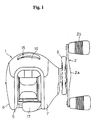
- FIG. 1 is a plan view of a double bearing reel in accordance with one embodiment of the present invention.
- the double bearing reel shown in the FIG. 1 is a bait reel mainly used for a lure fishing and includes a reel body 1, a handle 2, and a star drag 3.
- the handle 2 is provided for rotating a spool and is disposed at one side of the reel body 1.
- the star drag 3 is disposed between the handle 2 and the adjacent side of the reel body 1.
- the handle 2 is of a double handle type which includes an arm portion 2a and holding portions 2b, each of which is rotatably provided with respective end of the arm portion 2a.
- the outer surface of the arm portion 2a of the handle 2 is a smooth jointless surface so that a fishing line is not likely to become entwined around the arm portion 2a.
- the reel body 1 includes a frame 5, a first side cover 6, a second side cover 7, and a front cover 10.
- the first side cover 6 and the second side cover 7 are provided on respective opposite sides of the reel frame 5.
- the front cover 10 is disposed at a front portion of the frame 5 so as to be opened and closed.
- the frame 5 includes a pair of side plates 8 and 9, which are disposed so as to be opposed to each other with a space therebetween, and a plurality of connecting members (not shown) which connect the side plates 8 and 9.
- the brake case 50 has a short cylindrical shape and a bearing accommodating portion 50a that has a cylindrical shape and is formed at a central portion of the brake case 50.
- the bearing 35a for supporting the spool shaft 16 is accommodated in the bearing accommodating portion 50a and a friction plate 22a of the casting control mechanism 22 is attached thereto.
- the rotating member 51 is a disc-shaped member that is connected to the spool shaft 16 by serrations or gear teeth such that the spool shaft 16 and rotating member 51 are not rotatable with respect to one another.
- six concave attachment portions 51a are provided at circumferentially spaced apart locations adjacent to an outer peripheral surface of the rotating member 51.
- Each of the concave attachment portions 51a is open in to an axial face of the rotating member 51, as shown in FIGS. 3, 5 and 6.
- Each of the concave attachment portions 51a is an opening having a predetermined axial depth parallel to an axis of rotation of the spool 12.
- a bottom surface of each concave attachment portion 51a having a half-circular shape, as seen in FIG. 5.
- each of the pivoting brake members 53 extends into a corresponding one of the concave attachment portions 51a, with the pivoting brake members 53 retained for pivotal movement within the concave attachment portions 51a.
- a plate 56 is fixed to an axial surface of the rotating member 51, as shown in FIGS. 5 and 6, by a screw shown in FIG. 3.
- the plate 56 is formed with a plurality of circumferential notches or recesses through which a portion of each of the pivoting brake members 53 extends, as shown in FIG. 6.
- the pivoting brake members 53 are retained in the concave attachment portions 51a by the plate 56.
- a radially outward surface of each of the concave attachment portions 51a is inclined radially outward by an angle R1, as shown in FIG. 5.
- the angle R1 is measured with respect to a line that is parallel to the rotational axis of the spool shaft 16.
- the radially inward surface of each of the concave attachment portions 51 is inclined radially inward by an angle R2, as shown in FIG. 5.
- the angle R1 is also measured with respect to a line that is parallel to the rotational axis of the spool shaft 16.
- the inclined radially inward and outward surfaces of each concave attachment portion 51a are provided to limit radial angular inclination of each of the respective pivoting brake members 53.
- the angle R1 is preferably in the range of 3°to 5°and the angle R2 is preferably in the range of 5°to 9°.
- the angle R1 is determined so that the position of a tip end of each of the respective pivoting brake members 53 would extend into the brake liner 57 fixed to inside the brake housing 52. Further, the angle R1 is dimensioned to insure that the pivoting brake members 53 can easily engage the brake liner 57 when the brake liner 57 is moved into position for engagement with the pivoting brake members 53.
- a portion of the surface of the moving portion 53b of each of the pivoting brake members 53 is slightly inclined radially inwardly with respect to the rotational axis of the spool 12 in order to prevent the tip end of each pivoting brake member 53 from contacting the brake liner 57 of the brake housing 52 when the pivoting brake member 53 is urged radially outwardly.
- only the contact portion 53c makes contact with the brake liner 57 of the brake housing 52 in order to provide a braking force to the spool 12.
- the brake housing 52 includes an inner portion 52a, an outer portion 52b, and a middle portion 52c.
- the end of the brake liner 57 has a tapered surface 57a so as make an increase in height from an inner radial inner side to an outer radial side more gradual, as shown in FIG. 3.
- the pivoting brake members 53 are smoothly guided to the inner side of the brake liner 57 due to the presence of the tapered surface 57a.
- the cam mechanism 71 converts the rotational movement of the rotatable ring member 70 to axial movement of the brake liner 57 in a manner described in greater detail below.
- the returning spring 72 urges the brake housing 52 axially outward against the cam mechanism 71.
- the projecting portion 70c becomes aligned with numbers 0 through 5 (not shown) printed on the surface of the first side cover 6 adjacent to the oblong opening to provide an indication of the position of the rotatable ring member 70 thereby indicating the strength of braking force applied to the spool 12.
- a pair of rotation controlling concave portions 70b are formed on a radially inner periphery of the rotatable ring member 70 for limiting rotational movement of the rotatable ring member 70 with respect to the brake case 50.
- the rotatable ring member 70 is compressed against the brake case 50 by a pressing plate 75.
- the pressing plate 75 compresses the rotatable ring member 70 by means of screws, each of which is tighten against a respective screw base portion 50d formed on the outer side surface of the brake case 50.
- the screw base portion 50d protrudes radially outward.
- the range of the rotational angle of the rotatable ring member 70 is predetermined by the screw base portions 50d which stops the movement of the rotatable ring member 70 by contacting surfaces of respective rotation controlling concave portions 70b.
- the number of pivoting brake members 53 that are able to contact with the brake liner 57 is decreased and the braking force is reduced since the brake housing 52 is moved away from the rotating member 51 due to an urging force of the returning spring 72.
- the brake liner 57 moves to a position where all of the contact portions 53c on the pivoting brake members 53 are spaced apart from the brake liner 57, no braking force is exerted.
- the clutch chalk 40 is pressed inwardly and, hence, a clutch-on state is attained and the spool 12 can be rotated by rotation of the handle 2.
- rotational force applied to the handle 2 is transmitted to the spool 12 via the handle shaft 30, the main gear 31, the pinion gear 32 and the spool shaft 16 to rotate the spool 12 in the line-winding direction.
- centrifugal forces are exerted on the pivoting brake members 53 of the centrifugal braking mechanism 23 to move the pivoting brake members 53 radially outwardly.
- the brake housing 52 may be positioned at position 0 by rotating the rotatable ring member 70 in the direction indicated by the arrow B in FIG. 4 using the knob portion 70a.
- the brake liner 57 is positioned such that none of the pivoting brake members 53 are able to make contact with the brake liner 57 and there is no braking force by the centrifugal braking mechanism 23 is exerted on the spool 12.
- the user rotates the handle in order to engage the clutch mechanism 13 and rotate the spool 12 thereby winding in the fishing line.
- the thumb rest 17 is movable in a downward direction (with respect to FIGS. 1 and 2) in order to dis-engage the clutch mechanism 13. Due to the movement of the thumb rest 17, the clutch chalk 40 and the pinion gear 32 are moved outwardly to dis-engage the clutch mechanism 13. In the dis-engaged state, the rotation from the handle shaft 30 is not transmitted to neither the spool 12 nor the spool shaft 16 and the spool 12 may freely rotate.
- the spool shaft 16 is rotated in the line-releasing direction by the rotation of the spool 12, and the rotation is transmitted to the rotating member 51.
- the pivoting brake members 53 make contact with the brake liner 57 and the spool 12 is braked by the centrifugal braking mechanism 23 to prevent a generation of backlash.
- Each of the sliding brake members 66 includes a guiding portion 66a, a brake portion 66b, and one contact portion 66c.
- the guiding portion 66a has a cylindrical shape and is fitted onto the respective guiding shaft 65.
- the brake portion 66b extends in the axial direction from the guiding portion 66a.
- the contact portion 66c is disposed on the outer surface of the brake portion 66b and extends radially outward. As in the above-mentioned embodiment in FIGS. 1-7, there is only one contact portion 66c formed on any single sliding brake member 66. However, as indicated in phantom lines in FIG. 8, each contact portion 66c is located at a different position in the axial direction relative to the rotational axis of the spool 12.
- the alternate embodiment in FIG. 8 is such that as the brake liner 57 is adjustably moved toward the rotating member 51, the level of braking force may be increased in a step-wise fashion as, one by one, the various contact portions 66c are able to contact the brake liner 57.
- the adjustment of the braking force is easy since the number of the sliding brake members 66 which are able to make contact with the brake liner 57 is readily changeable by operating the adjusting mechanism 55 in the same manner as in the first embodiment (in FIGS. 1-7). Also, a large braking force is obtainable since the sliding brake members 66 are moved radially outwardly by the centrifugal forces. Moreover, a distinctive difference in the braking force may be obtained by the adjustment since the braking force is adjusted stepwise by changing the number of the contact portions 66c which make contact with the brake liner 57.
- the adjustment of the braking force may be easily carried out since the number of the pivoting brake members which are able to make contact with the braking liner is readily varied by operating the moving mechanism. Also, a large braking force is obtained since the pivoting brake members are moved outwardly in the radial direction by the centrifugal forces. Moreover, a distinctive difference in the braking force may be obtained by an adjustment since the braking force is adjusted stepwise by changing the number of the contacting portions which make contact with the braking liner.
Landscapes
- Life Sciences & Earth Sciences (AREA)
- Environmental Sciences (AREA)
- Animal Husbandry (AREA)
- Biodiversity & Conservation Biology (AREA)
- Braking Arrangements (AREA)
Abstract
Description
- The present invention relates to a centrifugal braking device. More specifically, the present invention relates to a centrifugal braking device for double bearing reel that is configured for providing braking force to a spool that is rotatably supported in a reel body of a double bearing reel, the centrifugal braking device working in response to centrifugal forces.
- A double bearing reel is mainly used for lure fishing and is also referred to as a bait reel. In such a double bearing reel, braking force is typically applied to the spool in order to prevent the generation of backlash caused when the rotation speed of a spool exceeds the releasing speed of a fishing line during a casting operation. A centrifugal braking device is one braking mechanism used for reducing backlash and is capable of braking the spool using centrifugal forces generated when the spool is rotated.
- In general, centrifugal braking devices include a plurality of brake members and a brake housing. The plurality of brake members are provided movably in a radial direction with respect to the spool or a rotating member which rotates together with the spool. The brake housing is a member having a cylindrical shape which is fixed to a reel body. The brake housing is disposed outside of the brake members so as to be capable of making contact with the brake members.
- In such a centrifugal braking device, when the spool rotates, the brake members are urged radially outwardly in centrifugal forces and make contact with a braking surface thereby braking rotation of the spool. Since the centrifugal force increases proportional to the square of the rotation speed of the spool, the generated braking force is not large when the spool rotates at a low speed as, for instance, when winding a fishing line around the spool. However, the generated braking force becomes significantly large when the spool is rotated at high speed as, for instance, during casting out of the fishing line. For this reason, the centrifugal braking device has a characteristic that although resistance generated during a fishing line winding operation is small, a large braking force may be generated when casting a fishing line to prevent backlash.
- In this kind of centrifugal braking device, the number of brake members which move in the radial direction may be varied in order to adjust the level of the braking force. For this reason, a rocking mechanism is provided with each of the brake members in order to switch the respective brake member from an operating position where the brake member may make contact with the brake housing, to a non-operating position where the brake member does not make contact with the brake housing.
- When, for instance, lure fishing is performed using a bait reel having the above described centrifugal braking device and lures of various weights such as a plug and a worm are used, the distance that a lure may be cast out varies depending on the weight of the lure. Thus, it is preferable, when lures of various weights are used, that the braking force be adjustable in accordance with the weight of the lure.
- In the conventional centrifugal braking devices described above, since the brake members move in the radial direction (the same direction as the centrifugal forces operate), a large braking force may be obtained. However, it is necessary to adjust the braking force by increasing or decreasing the number of the brake members which make contact with the brake housing using the rocking member provided with the respective brake member. Accordingly, it is difficult to adjust the braking force.
- Japanese Laid-Open patent application No. 10-304798 discloses a centrifugal braking device in which an adjustment of the braking force may be carried out by touching a dial exposed outside of a reel body.
- The above centrifugal braking device includes a rotating member, a plurality of brake members, a brake housing, and a moving mechanism. The rotating member rotates together with the spool. The plurality of brake members are movably supported by the rotating member. The brake housing is provided on the reel body so as to reciprocate in the spool axis direction. The tip of the respective brake members may make contact with the brake housing. The moving mechanism includes the rotary dial and it reciprocates the brake housing. A contacting portion is formed at a tip of the respective brake member for making contact with the brake housing. The brake housing is a disc-shape member provided with a ring-shape brake shoe at its periphery which makes contact with the contacting portion. The brake housing reciprocates in the spool axis direction when the dial of the moving mechanism is rotated.
- In the above-mentioned conventional centrifugal braking device, the brake members are moved radially outwardly with respect to the spool axis when the spool is rotated due to the centrifugal force exerted on the brake members such that the brake members make contact with the brake shoe to brake the spool. The braking force may be adjusted by rotating the dial to move the brake housing such that an angle of each respective brake member is varied when it makes contact with the brake shoe.
- Although the adjustment of the braking force may be easily carried out by rotating the dial in the above conventional centrifugal braking device, a large braking force is hardly obtained since the braking force which is exerted upon making contact with the brake shoe is obtained by the force of the movement of the brake members outwardly in the axial direction. That is, since the brake members move outwardly in the axial direction, not outwardly in the radial direction, it is difficult to efficiently obtain a centrifugal force which acts in the radial direction as a braking force. Moreover, since the braking force is adjusted by varying the angle of the respective brake member, the change in the braking force when the brake housing is moved in the spool axis direction is small and, hence, one can hardly feel a distinctive change in the braking force.
- Accordingly, one object of the present invention is to provide a centrifugal braking device for a double bearing reel in which braking force is easily adjusted ,a large braking force is obtainable, and distinctive differing levels in braking force are easily selected.
- In accordance with one aspect of the present invention, there is a centrifugal braking device in a double bearing reel. The double bearing reel has a reel housing and a spool rotatably supported within the reel housing. The centrifugal braking device provides braking force to the spool in response to centrifugal forces and includes a plurality of circumferentially spaced apart brake members supported within the reel housing for rotation with the spool. The brake members are movable in a radially outward direction in response to centrifugal forces. Each of the plurality of brake members has a contact portion and each contact portion is located at a different position in an axial direction relative to the spool. The centrifugal braking device also includes a brake housing supported in the reel housing. The brake housing has a cylindrical shape and is non-rotatable with respect to the reel housing. The brake housing is selectively movable in the axial direction relative to the spool such that in a retracted position the brake housing is spaced apart from each of the contact portions such that none of the contact portions is contactable with the brake housing in response to centrifugal forces, and in a non-retracted position at least one of the contact portions is contactable with the brake housing for generating braking force in response to centrifugal forces. The centrifugal braking device also includes a means for selectively positioning the brake housing in a plurality of axial positions in the axial direction relative to the spool.
- Preferably, the centrifugal braking device also includes a rotating member coupled to the spool for rotation therewith. The rotating member is formed with means for supporting the plurality of brake members such that at least a portion of each of the brake members is urged radially outward in response to centrifugal forces.
- Preferably, each of the brake members are supported on a portion of the rotating member for pivotal movement.
- Preferably, the means for selectively positioning the brake housing includes a rotatable ring member rotatably supported on the reel housing. The ring member has a first cam contacting a second cam on the brake housing such that rotation of the rotatable ring member changes the axial position of the brake housing relative to the spool. Further, an urging member contacts the brake housing for urging the brake housing in an axial direction away from the rotating member.
- Preferably, the rotatable ring member is formed with a knob portion that extends in an axial direction, the knob portion extending through an opening in a side cover of the reel housing for operating the means for selectively positioning the brake housing.
- Preferably, the means for supporting the plurality of brake members on the rotating member includes a plurality of concave portions formed in an axial face of the rotating member proximate a radially outer periphery thereof, a portion of each of the brake members being retained for pivotal movement in the concave portions.
- Preferably, each of the concave portions includes angle controlling means for controlling angular displacement of each of the brake members with respect to pivotal movement thereof, such that radially outward movement of a tip end of each of the brake members is confined within a space defined by an inner radius of the brake housing.
- Alternatively, the means for supporting the plurality of brake members on the rotating member includes a plurality of radially extending shafts fixed to the rotating member, and each of the brake members is disposed on a corresponding one of the shafts such that the brake members may undergo movement in radial directions relative to the spool and the brake members are confined against rotational movement with respect to the shafts..
- Preferably, the brake housing includes a brake liner fixed to an inner radial surface of the brake housing, the brake liner for contacting the contact portions on each of the brake members.
- In the above recited centrifugal braking device, the plurality of brake members move outwardly in the radial direction, not outwardly in an axial direction when the spool is rotated, and the contacting portions of the respective brake members contact the inner periphery of the brake housing so that a braking force is applied to the spool. The number of the contacting portions which make contact with the brake housing of cylindrical shape may be varied by moving the brake housing in the axial direction by using the altering the axial position of the brake housing. Since the location of each contact portion differs in the axial direction relative to the spool on each respective brake member, changes in the axial position of the brake housing changes the number of contact portions that may contact the brake housing for generating braking force. Since the number of the brake members which make contact with the brake housing may be readily changed by adjusting the axial location of the brake housing, the adjustment of the braking force is simple and easy. Also, since a braking of the spool is achieved by moving the brake members radially outward using centrifugal forces, a large braking force may be obtained. Moreover, since the adjustment in the braking force is carried out by changing the number of the contact portions which make contact with the brake housing, the braking force changes in a stepwise manner and a distinctive difference in the braking force may be obtained.
- These and other objects, features, aspects and advantages of the present invention will become apparent to those skilled in the art from the following detailed description, which, taken in conjunction with the annexed drawing, discloses a preferred embodiment of the present invention.
- Referring now to the attached drawing which forms a part of this disclosure:
- FIG. 1 is a plan view of a double bearing reel in accordance with one embodiment of the present invention;
- FIG. 2 is a cross-sectional view of the double bearing reel depicted in FIG. 1;
- FIG. 3 is an enlarged cross-sectional view of a centrifugal braking mechanism of the double bearing reel depicted in FIGS. 1 and 2;
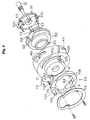
- FIG. 4 is an exploded perspective view of the centrifugal braking mechanism depicted in FIG. 3;
- FIG. 5 is a fragmentary cross-sectional view of a portion of the double bearing reel depicted in FIGS. 1, 2, 3 and 4 showing one of a plurality of pivoting brake members, the pivoting brake members being circumferentially spaced apart from one another;
- FIG. 6 is a cross-sectional view cut taken along the line VI - VI in FIG. 5;
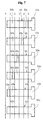
- FIG. 7 is a schematic diagram showing several of the pivoting brake members laid out linearly to demonstrate which ones make contact with a brake liner during the adjustment of braking force; and
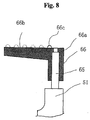
- FIG. 8 is similar to FIG. 5 showing a pivoting brake member in accordance with an alternate embodiment of the present invention.
-
- FIG. 1 is a plan view of a double bearing reel in accordance with one embodiment of the present invention.
- The double bearing reel shown in the FIG. 1 is a bait reel mainly used for a lure fishing and includes a
reel body 1, ahandle 2, and astar drag 3. Thehandle 2 is provided for rotating a spool and is disposed at one side of thereel body 1. Thestar drag 3 is disposed between thehandle 2 and the adjacent side of thereel body 1. Thehandle 2 is of a double handle type which includes anarm portion 2a and holdingportions 2b, each of which is rotatably provided with respective end of thearm portion 2a. The outer surface of thearm portion 2a of thehandle 2 is a smooth jointless surface so that a fishing line is not likely to become entwined around thearm portion 2a. - As shown in FIG. 2, the
reel body 1 includes aframe 5, a first side cover 6, asecond side cover 7, and afront cover 10. The first side cover 6 and thesecond side cover 7 are provided on respective opposite sides of thereel frame 5. Thefront cover 10 is disposed at a front portion of theframe 5 so as to be opened and closed. Theframe 5 includes a pair ofside plates side plates - The
second side cover 7 is located on the same side of theframe 5 as thehandle 2 and thesecond side cover 7 is fixed to theside plate 9 by, for instance, screws so that theside cover 7 is detachable from theside plate 9. The first side cover 6 is located on the opposite side of thereel body 1 fromhandle 2 and is attached to theside plate 8 by abayonet structure 14 such that the first side cover 6 is detachable from theside plate 8, as is described in greater detail below. Anopening 8a is formed in theside plate 8 such that aspool 12 extends there through. - Within the
frame 5 are the following: thespool 12, alevel wind mechanism 15, and athumb rest 17. Thelevel wind mechanism 15 is provided for uniformly winding a fishing line around thespool 12. Thethumb rest 17 is shaped such that a fisherman's thumb may rest on thethumb rest 17 operation of the fishing reel. Thethumb rest 17 is also serves as a clutch lever, as is described in greater detail below. Agear mechanism 18, aclutch mechanism 13, aclutch switching mechanism 19, adrag mechanism 21, and acasting control mechanism 22 are also provided in the space between theframe 5 and thesecond side cover 7. - The
gear mechanism 18 is configured to transmit rotational force from thehandle 2 to thespool 12 and to thelevel wind mechanism 15. Theclutch switching mechanism 19 is configured to switch theclutch mechanism 13 from engagement to dis-engagement in response to pressing thethumb rest 17 downward. Thedrag mechanism 21 is configured to provide braking force to thespool 12 when the fishing line is released or cast out. Thecasting control mechanism 22 is configured to provide braking force to thespool 12 by engaging ends of aspool shaft 16. Further, a centrifugal braking mechanism 23 provided between theframe 5 and the first side cover 6 prevents backlash as the fishing line is cast out from thespool 12. Each of the above identified portions of the present invention are described in greater detail below. - The
spool 12 is formed withflange portions 12a, each having a plate-like shape. Theflange portions 12a are formed at both opposite sides of thespool 12. Thespool 12 is also formed with aspool body 12b having a cylindrical shape. Thespool body 12b extends between and are formed integrally with theflange portions 12a. Thespool 12 has aboss portion 12c having a cylindrical shape that is integrally formed radially inward from thespool body 12b. Thespool 12 is fitted to thespool shaft 16 with thespool shaft 16 extending through a central bore formed in theboss portion 12c. Specifically, the inner surface of theboss portion 12c and the shaft are formed with serrations or gear teeth such that thespool 12 and thespool shaft 16 are non-rotatable with respect to one another. - The
spool shaft 16 extends through an opening formed in theside plate 9 and further extends outside of thesecond side cover 7. The second side cover is formed with aboss portion 29, as shown in FIG. 2. One end of thespool shaft 16 is rotatably supported by abearing 35b retained within theboss portion 29. An opposite end of thespool shaft 16 is rotatably supported by abearing 35a of the centrifugal braking mechanism 23, as shown in FIGS. 2 and 3. - The
level wind mechanism 15 includes a guidingrod 25, aworm shaft 26, and aline guide 27. The guidingrod 25 is fixed to each of theside plates worm shaft 26 is supported at opposite ends on theside plates rod 25. Agear 28a, which forms a part of thegear mechanism 18, is fixed to one end of theworm shaft 26. Aspiral groove 26a is formed on theworm shaft 26. A guiding member (not shown) that is supported on theline guide 27 is engaged with the worm shaft by extending into thespiral groove 26a. For this reason, theline guide 27 undergoes reciprocating movement along the guidingrod 25 in response to rotation of theworm shaft 26 via thegear mechanism 18. A fishing line (not shown) extending through a guiding hole in theline guide 27 is thereby uniformly wound around thespool 12. - The
gear mechanism 18 includes amain gear 31, apinion gear 32, the above-mentionedgear 28a, and agear 28b as shown in FIG. 2. Themain gear 31 is fixed to ahandle shaft 30. Thepinion gear 32 has a cylindrical shape and engages with themain gear 31. Thegear 28a is fixed to one end of theworm shaft 26. Thegear 28b is fixed to thehandle shaft 30 such that thegear 28b rotates with thehandle shaft 30. Thegear 28b is further engaged with thegear 28a. - The
pinion gear 32 is generally a cylindrically shaped member that is extends along an outer periphery of a portion of one end of thespool shaft 16. Thepinion gear 32 extends through an aperture formed in theside plate 9 such that most of thepinion gear 32 extends to an outward side of the side plate 9 (toward the right side in FIG. 2). Thepinion gear 32 is engaged for rotation with thespool shaft 16 but may undergo movement in the axial direction along a portion of the length of thespool shaft 16. - The
pinion gear 32 includesgear teeth portion 32a and an engagingportion 32b. Theteeth portion 32a is located at right hand side of thereel body 1 shown in FIG. 2 for engagement with themain gear 31. The engagingportion 32b is formed at an opposite side of thepinion gear 32. Acylindrical portion 32c is provided between theteeth portion 32a and the engagingportion 32b. - A
clutch pin 16a extends through a portion of thespool shaft 16, as shown in FIG. 2. The engagingportion 32b is formed with two recesses at radially opposite sides of the end surface of thepinion gear 32 for receiving theclutch pin 16a. When thepinion gear 32 is positioned as depicted in FIG. 2, there is engagement between engagingportion 32b of thepinion gear 32 and thespool shaft 16 such that rotation of thepinion gear 32 causes rotation of the spool shaft. Thepinion gear 32 may also be moved outwardly (toward the right side of FIG. 2) such that theclutch pin 16a no longer engages the recesses formed in the end of thepinion gear 32 thereby disengaging the pinion gear from thespool shaft 16 such that thespool shaft 16 is free to rotate with respect to thepinion gear 32. Theclutch mechanism 13 includes the recesses formed on the end surface of the engagingportion 32b of thepinion gear 32 and theclutch pin 16a. - As shown in FIG. 2, the
thumb rest 17 is disposed on a back portion of thespool 12 between the pair of theside plates thumb rest 17 serves as a clutch operation lever and is supported on ashaft 17a. Elongated holes (not shown) are provided with theside plates frame 5 such that theshaft 17a extends through the elongated holes of theside plates shaft 17a of thethumb rest 17 is connected to a clutch chalk 40 (a cam member). Movement of theshaft 17a along the length of the elongated holes causes movement of the clutch chalk 40 parallel to the axis of thespool shaft 16. The clutch chalk 40,shaft 17a andthumb rest 17 are all part of theclutch switching mechanism 19. Although not depicted, theclutch switching mechanism 19 includes moving linkage between thehandle shaft 30 and the clutch chalk 40 such that rotation of thehandle shaft 30 causes engagement of theclutch mechanism 13 where the chalk 40 is urged to move thepinion gear 32 into engagement with thepin 16a thereby ensuring rotation of thespool shaft 16. - In the above described configuration, the
pinion gear 32 is normally located in a clutch engagement position so that the engagingportion 32b is engaged with theclutch pin 16a with thespool shaft 16 in a clutch-on state. On the other hand, when thepinion gear 32 is moved outwardly (toward the right side of FIG. 2) by the clutch chalk 40, the engagingportion 32b is disengaged from theclutch pin 16a to enter a clutch-off state. - As shown in FIG. 3, the centrifugal braking mechanism 23 includes a
brake case 50, a rotatingmember 51, abrake housing 52, a plurality of pivotingbrake members 53, and anadjusting mechanism 55. The rotatingmember 51 is disposed within thebrake case 50 and is fitted onto a portion of thespool shaft 16 for rotation together with thespool 12. Thebrake housing 52 is disposed within thebrake case 50 but is axially movable along the spool rotation axis, as is described in greater detail below. - The plurality of pivoting
brake members 53 are pivotally supported on the rotatingmember 51 such that centrifugal forces due to rotation of the rotatingmember 51 urge the pivotingbrake members 53 radially outward. In this embodiment, there are six of the plurality of pivotingbrake members 53, however it is possible to construct the centrifugal braking mechanism 23 with either a greater number or smaller number of pivotingbrake members 53. Theadjusting mechanism 55 is a mechanism for positioning thebrake housing 52 within thebrake case 50 at predetermined positions along the spool rotation axis, as is described below. - The
brake case 50 has a short cylindrical shape and a bearingaccommodating portion 50a that has a cylindrical shape and is formed at a central portion of thebrake case 50. Thebearing 35a for supporting thespool shaft 16 is accommodated in the bearingaccommodating portion 50a and afriction plate 22a of thecasting control mechanism 22 is attached thereto. - As shown in FIG. 2, the
brake case 50 is fixed to the first side cover 6 by a screw 60. That is, once attached to the first side cover 6, thebrake case 50 forms a part of thereel body 1. Also, a locatingsnap ring 61 is attached to an outer periphery of the tip of the bearingaccommodating portion 50a. The locatingsnap ring 61 retains in position an end of a returningspring 72. The returningspring 72 forms a part of theadjusting mechanism 55, as is described further below. - The
bayonet mechanism 14 includes three circumferentially spaced apart projectingportions 14a formed on an outer peripheral surface of thebrake case 50. Also, three circumferentially spaced apartclaws 8b are disposed on the inner surface of theopening 8a at a positions corresponding to the positions of the projectingportions 14a. Theclaws 8b project radially inwardly from the surface of theopening 8a. The first side cover 6 andbrake case 50 may be removed from theside plate 8 by rotating thereby bringing the projectingportions 14a out of circumferential alignment with theclaws 8b. - The rotating
member 51 is a disc-shaped member that is connected to thespool shaft 16 by serrations or gear teeth such that thespool shaft 16 and rotatingmember 51 are not rotatable with respect to one another. In this embodiment, sixconcave attachment portions 51a are provided at circumferentially spaced apart locations adjacent to an outer peripheral surface of the rotatingmember 51. Each of theconcave attachment portions 51a is open in to an axial face of the rotatingmember 51, as shown in FIGS. 3, 5 and 6. Each of theconcave attachment portions 51a is an opening having a predetermined axial depth parallel to an axis of rotation of thespool 12. A bottom surface of eachconcave attachment portion 51a having a half-circular shape, as seen in FIG. 5. - One end of each of the pivoting
brake members 53 extends into a corresponding one of theconcave attachment portions 51a, with the pivotingbrake members 53 retained for pivotal movement within theconcave attachment portions 51a. Aplate 56 is fixed to an axial surface of the rotatingmember 51, as shown in FIGS. 5 and 6, by a screw shown in FIG. 3. Theplate 56 is formed with a plurality of circumferential notches or recesses through which a portion of each of the pivotingbrake members 53 extends, as shown in FIG. 6. The pivotingbrake members 53 are retained in theconcave attachment portions 51a by theplate 56. - A radially outward surface of each of the
concave attachment portions 51a is inclined radially outward by an angle R1, as shown in FIG. 5. The angle R1 is measured with respect to a line that is parallel to the rotational axis of thespool shaft 16. Also, the radially inward surface of each of theconcave attachment portions 51 is inclined radially inward by an angle R2, as shown in FIG. 5. The angle R1 is also measured with respect to a line that is parallel to the rotational axis of thespool shaft 16. The inclined radially inward and outward surfaces of eachconcave attachment portion 51a are provided to limit radial angular inclination of each of the respectivepivoting brake members 53. The angle R1 is preferably in the range of 3°to 5°and the angle R2 is preferably in the range of 5°to 9°. The angle R1 is determined so that the position of a tip end of each of the respectivepivoting brake members 53 would extend into thebrake liner 57 fixed to inside thebrake housing 52. Further, the angle R1 is dimensioned to insure that the pivotingbrake members 53 can easily engage thebrake liner 57 when thebrake liner 57 is moved into position for engagement with the pivotingbrake members 53. - Each of the pivoting
brake members 53 is pivotally provided within respectiveconcave attachment portions 51a of the rotatingmember 51. As shown in FIGS. 5 and 6, each pivotingbrake member 53 includes ashaft portion 53a, a movingportion 53b, and a plurality ofcontact portions 53c. Theshaft portion 53a is disposed in theconcave attachment portion 51a. The movingportion 53b extends from theshaft portion 53a outwardly in a direction generally parallel to the rotational axis of thespool 12. Thecontact portions 53c are provided are positioned at various locations on the movingportion 53b of pivotingbrake member 53 such that eachcontact portion 53c extends radially outward with respect to the rotational axis of thespool 12. - However, as shown in FIG. 7, the position of the
contact portions 53c on each respectivepivoting brake members 53 differ from the other pivotingbrake members 53. Specifically, in FIG.7, the pivotingbrake members 53 are laid out flat side by side. The pivotingbrake member 53 at the top of FIG. 7 has acontact portion 53c atposition 5. The nextpivoting brake member 53 in FIG. 7 has acontact portion 53c atposition 4. The nextpivoting brake member 53 in FIG. 7 has acontact portion 53c atposition 3. The nextpivoting brake member 53 in FIG. 7 has acontact portion 53c atposition 3, and so on. However, the lastpivoting brake member 53 at the bottom if FIG. 7 has no contact portion. The lastpivoting brake member 53 having nocontact portion 53c is provided in order to maintain rotational balance. The five positions of thecontact portions 53c are equally spaced apart from one another with respect to the rotational axis of thespool 12. It should be understood that FIG. 5 shows a composite of all of the pivotingbrake members 53 such that all of five of thecontact portions 53c are visible. However, only onecontact portion 53c is formed on any one of the pivotingbrake members 53 having a contact portion. - As is indicated in FIG. 5, a portion of the surface of the moving
portion 53b of each of the pivotingbrake members 53 is slightly inclined radially inwardly with respect to the rotational axis of thespool 12 in order to prevent the tip end of each pivotingbrake member 53 from contacting thebrake liner 57 of thebrake housing 52 when the pivotingbrake member 53 is urged radially outwardly. In other words, only thecontact portion 53c makes contact with thebrake liner 57 of thebrake housing 52 in order to provide a braking force to thespool 12. - As shown in FIG.3, the
brake housing 52 includes aninner portion 52a, anouter portion 52b, and amiddle portion 52c. - The
inner portion 52a of thebrake housing 52 is supported by the bearingaccommodating portion 50a such that thebrake housing 52 is movable in the axial direction along the outer surface of the bearingaccommodating portion 50a. Theouter portion 52b of thebrake housing 52 is engaged with the inner surface of thebrake case 50 so as to be movable in the axial direction but is non-rotatable with respect to thebrake case 50. Themiddle portion 52c extends between theinner portion 52a and theouter portion 52b. Thebrake liner 57 is fixed to the inner surface of theouter portion 52b as shown in FIG. 3. Thecontact portions 53c of the various pivotingbrake members 53 make contact with the inner surface of thebrake liner 57 depending upon the position of thebrake housing 52 andbrake liner 57, as is described below. The end of thebrake liner 57 has a taperedsurface 57a so as make an increase in height from an inner radial inner side to an outer radial side more gradual, as shown in FIG. 3. The pivotingbrake members 53 are smoothly guided to the inner side of thebrake liner 57 due to the presence of the taperedsurface 57a. - A second end of the returning
spring 72 contacts a bottom surface of theinner portion 52a. For this reason, thebrake housing 52 is always urged outwardly in the axial direction away from thespool 12. A pair of stop pins 62 that extend radially outward from opposite sides of thebrake housing 52. The pair of stop pins 62 extend into and are engaged with a pair ofgrooves 50b formed on the inner surface of thebrake case 50, as shown in FIG. 3, such that thebrake housing 52 is attached to thebrake case 50 in a non-rotatable manner but is movable in an axial direction with respect to the rotational axis of thespool 12. - The
brake housing 52 is formed with at least twofirst cams 63 that extend outwardly in the axial direction relative to thespool 12. Thefirst cams 63 have a substantially triangular shape and form a part of theadjusting mechanism 55, as is described further below. - As shown in FIG. 4, the adjusting
mechanism 55 includes arotatable ring member 70, acam mechanism 71, and the returningspring 72. - The
rotatable ring member 70 is rotatably retained between thebrake case 50 and apressing plate 75 that is described in greater detail below. - The
cam mechanism 71 converts the rotational movement of therotatable ring member 70 to axial movement of thebrake liner 57 in a manner described in greater detail below. The returningspring 72 urges thebrake housing 52 axially outward against thecam mechanism 71. - The
rotatable ring member 70 is a ring-shape member which is rotatably contacts the outer surface of thebrake case 50. Aknob portion 70a is formed on the outer surface of therotatable ring member 70. Theknob portion 70a is positioned to extend axially outwardly in a direction parallel to the rotational axis of thespool 12. A projectingportion 70c is formed on the central portion of theknob portion 70a so as to extend through an oblong opening in the surface of the first side cover 6. - As the
rotatable ring member 70 is rotated to various positions (described further below) the projectingportion 70c becomes aligned withnumbers 0 through 5 (not shown) printed on the surface of the first side cover 6 adjacent to the oblong opening to provide an indication of the position of therotatable ring member 70 thereby indicating the strength of braking force applied to thespool 12. A pair of rotation controllingconcave portions 70b are formed on a radially inner periphery of therotatable ring member 70 for limiting rotational movement of therotatable ring member 70 with respect to thebrake case 50. - A
positioning mechanism 73 is provided on therotatable ring member 70 for aligning therotatable ring member 70 with a predetermined rotational displacement angle corresponding to one of six different positions relative to thebrake case 50. - The
positioning mechanism 73 includes a positioning pin 73a, a coil spring 73b, andconcave positioning holes 73c. The positioning pin 73a is attached to therotatable ring member 70 movably in the spool axis direction. The coiled spring 73b urges the positioning pin 73a toward the adjacent surface of thebrake case 50. There are sixconcave positioning holes 73c in the depicted embodiment corresponding to the number of pivotingbrake members 53. Theconcave positioning holes 73c are formed on the axial side surface of thebrake case 50 at circumferentially spaced apart positions. -
Second cams 64 are formed on one side surface of therotatable ring member 70 and form part of thecam mechanism 71. Each of thesecond cams 64 is formed at a position corresponding to the position of the respectivefirst cam 63, and has a triangular oblique shape. The rotational movement of therotatable ring member 70 is converted into axial movement of thebrake housing 52 due to contact between the first andsecond cams second cams cam openings 50c formed in thebrake case 50. Each of thecam openings 50c has an arcuate shape to accommodate a corresponding arcuate shape of the first andsecond cams - The
rotatable ring member 70 is compressed against thebrake case 50 by apressing plate 75. Thepressing plate 75 compresses therotatable ring member 70 by means of screws, each of which is tighten against a respectivescrew base portion 50d formed on the outer side surface of thebrake case 50. Thescrew base portion 50d protrudes radially outward. The range of the rotational angle of therotatable ring member 70 is predetermined by thescrew base portions 50d which stops the movement of therotatable ring member 70 by contacting surfaces of respective rotation controllingconcave portions 70b. - In the
adjusting mechanism 55 having the above-described configuration, using theknob portion 70a, when therotatable ring member 70 is rotated in a direction indicate by an arrow A in FIG. 4, thebrake housing 52 is moved toward the rotatingmember 51 due to the interaction between the first andsecond cams brake members 53 that are able to contact with thebrake liner 57 is increased and the braking force is correspondingly increased. On the other hand, when therotatable ring member 70 is rotated in the direction indicated by an arrow B in FIG. 4, the number of pivotingbrake members 53 that are able to contact with thebrake liner 57 is decreased and the braking force is reduced since thebrake housing 52 is moved away from the rotatingmember 51 due to an urging force of the returningspring 72. When thebrake liner 57 moves to a position where all of thecontact portions 53c on the pivotingbrake members 53 are spaced apart from thebrake liner 57, no braking force is exerted. - FIG. 7 shows the various stages of possible brake force that can be applied by the pivoting
brake members 53 on thebrake liner 57. For instance, when thebrake liner 57 is located at a most advanced position shown in the right hand side of FIG. 7, as indicated by thenumber 5, the largest possible braking force is possible since all thecontact portions 53c are in a position to make contact with thebrake liner 57. On the other hand, when thebrake liner 57 is located at a position corresponding to 0 at the left hand side of FIG. 7, no braking force can be generated because none of thecontact portions 53c are able to make contact with thebrake liner 57. In this embodiment, the number of the pivotingbrake members 53 may be adjusted one by one such that any incremental number between 0 and 6 may be selected, the incremental number corresponding to the number of contact portions that may make contact with thebrake liner 57. - Since the pivoting
brake members 53 extend in an axial direction but may pivot in a radially outward direction relative to the rotational axis of thespool 12, a relatively large centrifugal force is exerted on the pivotingbrake members 53. As a result, a large braking force may be obtained. Further, six distinctively different levels in the braking force may be selected during adjustment of the braking force since the braking force is digitally adjusted (i.e., stepwise) by changing the number of the contact portions on respectivepivoting brake members 53 that are able to contact with thebrake liner 57. - In a normal operating state, the clutch chalk 40 is pressed inwardly and, hence, a clutch-on state is attained and the
spool 12 can be rotated by rotation of thehandle 2. Specifically, rotational force applied to thehandle 2 is transmitted to thespool 12 via thehandle shaft 30, themain gear 31, thepinion gear 32 and thespool shaft 16 to rotate thespool 12 in the line-winding direction. As thespool 12 rotates, centrifugal forces are exerted on the pivotingbrake members 53 of the centrifugal braking mechanism 23 to move the pivotingbrake members 53 radially outwardly. However, since the rotation speed of thespool 12 is typically low when winding in a fishing line, the braking force created by contact between the pivoting brake members and thebrake liner 57 is correspondingly low. Hence, the braking force created under such conditions does not interfere with the rotation of thehandle 2. However, should it be necessary to reduce the braking force, thebrake housing 52 may be positioned atposition 0 by rotating therotatable ring member 70 in the direction indicated by the arrow B in FIG. 4 using theknob portion 70a. As a result, thebrake liner 57 is positioned such that none of the pivotingbrake members 53 are able to make contact with thebrake liner 57 and there is no braking force by the centrifugal braking mechanism 23 is exerted on thespool 12. - When a fishing line to be cast out, the
clutch mechanism 13 is changed to a dis-engaged state by pressing thethumb rest 17 downward thereby moving the engagingportion 32b out of contact with thepin 16a. Thespool 12 may rotate in order to cast out the fishing line. As thespool 12 rotates, braking force applied to thespool 12 by contact between the pivotingbrake members 53 and thebrake liner 57. The braking force is adjustable to a desired level by a user to prevent backlash by rotating therotatable ring member 70 via manipulation of theknob portion 70a. As thebrake housing 52 is gradually moved toward the rotatingmember 51 by rotating therotatable ring member 70 in the direction indicated by the arrow A (FIG. 4), the number of the pivotingbrake members 53 which are able to make contact with thebrake liner 57 is increased. As a result, the braking force exerted by the centrifugal braking mechanism 23 is gradually increased. When thebrake liner 57 reaches the most advanced position, all the pivotingbrake members 52 are able to make contact with thebrake liner 57 and the braking force is able to reach a maximum level in response to centrifugal forces. - Once the fishing line is cast out, the user rotates the handle in order to engage the
clutch mechanism 13 and rotate thespool 12 thereby winding in the fishing line. - In this embodiment, the
thumb rest 17 is movable in a downward direction (with respect to FIGS. 1 and 2) in order to dis-engage theclutch mechanism 13. Due to the movement of thethumb rest 17, the clutch chalk 40 and thepinion gear 32 are moved outwardly to dis-engage theclutch mechanism 13. In the dis-engaged state, the rotation from thehandle shaft 30 is not transmitted to neither thespool 12 nor thespool shaft 16 and thespool 12 may freely rotate. When a fishing rod is swung in the clutch disengaged state so that the reel is inclined in the axis direction in order for thespool shaft 16 to face a vertical surface while thumbing the spool using a thumb on thethumb rest 17, a lure is cast and thespool 12 rotates vigorously in the line-releasing direction. - In this state, the
spool shaft 16 is rotated in the line-releasing direction by the rotation of thespool 12, and the rotation is transmitted to the rotatingmember 51. When the rotatingmember 51 is rotated, the pivotingbrake members 53 make contact with thebrake liner 57 and thespool 12 is braked by the centrifugal braking mechanism 23 to prevent a generation of backlash. - However, even if some backlash of the
spool 12 occurs resulting in a fishing line tangle, the first side cover 6 is easily removed due to thebayonet structure 14. Once the first side cover 6 is removed, thespool 12 may also be removed and a tangle may be untangled. - Moreover, if the lure is changed to one having a different weight, the braking force may be adjusted in accordance with the weight of the lure, by rotating the
rotatable ring member 70 using theknob portion 70a. In this embodiment, the braking force is easily adjusted by simply rotating therotatable ring member 70 using theknob portion 70a which is exposed to outside of the reel. Further, in accordance with the present invention, a large braking force is obtained and the difference in the braking force becomes distinctive when it is adjusted. -
- (a) Although the
brake housing 52 is moved in the axial direction in the above embodiment, the rotatingmember 51 may alternatively be moved in the axial direction in order to adjust the level of the braking force. - (b) Although the
brake housing 52 is moved by using the cam mechanism in the above embodiment, the position of thebrake housing 52 may be adjusted by other means (other than cams), for instance, a screw driven mechanism may be utilized. - (c) Although the pivoting
brake members 53 are movably provided with the rotatingmember 51 in the above embodiment, slidingbrake members 66 may be provided on the rotatingmember 51 movably in the radius direction as shown in FIG. 8. In this case, a plurality of guidingshafts 65, for instance six, have a square cross-section to prevent rotation of the slidingbrake members 66 on the guidingshafts 65. The guidingshafts 65 extend radially outward and are circumferentially spaced apart from one another on an outer periphery of the rotatingmember 51. Each of the slidingbrake members 66 is fitted on a respective one of the guidingshafts 65 such that the slidingbrake members 66 may move radially outward but may not rotate about the respective guidingshaft 65. -
- Each of the sliding
brake members 66 includes a guidingportion 66a, abrake portion 66b, and onecontact portion 66c. The guidingportion 66a has a cylindrical shape and is fitted onto the respective guidingshaft 65. Thebrake portion 66b extends in the axial direction from the guidingportion 66a. Thecontact portion 66c is disposed on the outer surface of thebrake portion 66b and extends radially outward. As in the above-mentioned embodiment in FIGS. 1-7, there is only onecontact portion 66c formed on any single slidingbrake member 66. However, as indicated in phantom lines in FIG. 8, eachcontact portion 66c is located at a different position in the axial direction relative to the rotational axis of thespool 12. As with the embodiment in FIGS. 1-7, the alternate embodiment in FIG. 8 is such that as thebrake liner 57 is adjustably moved toward the rotatingmember 51, the level of braking force may be increased in a step-wise fashion as, one by one, thevarious contact portions 66c are able to contact thebrake liner 57. - In this alternate embodiment the adjustment of the braking force is easy since the number of the sliding
brake members 66 which are able to make contact with thebrake liner 57 is readily changeable by operating theadjusting mechanism 55 in the same manner as in the first embodiment (in FIGS. 1-7). Also, a large braking force is obtainable since the slidingbrake members 66 are moved radially outwardly by the centrifugal forces. Moreover, a distinctive difference in the braking force may be obtained by the adjustment since the braking force is adjusted stepwise by changing the number of thecontact portions 66c which make contact with thebrake liner 57. - According to the present invention, the adjustment of the braking force may be easily carried out since the number of the pivoting brake members which are able to make contact with the braking liner is readily varied by operating the moving mechanism. Also, a large braking force is obtained since the pivoting brake members are moved outwardly in the radial direction by the centrifugal forces. Moreover, a distinctive difference in the braking force may be obtained by an adjustment since the braking force is adjusted stepwise by changing the number of the contacting portions which make contact with the braking liner.
- Various details of the invention may be changed without departing from its scope.
Furthermore, the foregoing description of the embodiments according to the present invention is provided for the purpose of illustration only, and not for the purpose of limiting the invention as defined by the appended claims.
Claims (9)
- A centrifugal braking device in a double bearing reel, the double bearing reel having a reel housing and a spool rotatably supported within said reel housing, the centrifugal braking device for providing braking force to the spool in response to centrifugal forces, comprising:a plurality of circumferentially spaced apart brake members supported within said reel housing for rotation with said spool, said brake members movable in a radially outward direction in response to centrifugal forces, each of said plurality of brake members having a contact portion, each contact portion being located at a different position in an axial direction relative to said spool;a brake housing supported in said reel housing, said brake housing having a cylindrical shape, said brake housing being a non-rotatable with respect to said reel housing, said brake housing being selectively movable in the axial direction relative to said spool such that in a retracted position said brake housing is spaced apart from each of said contact portions such that none of said contact portions is contactable with said brake housing in response to centrifugal forces, and in a non-retracted position at least one of said contact portions is contactable with said brake housing for generating braking force in response to centrifugal forces; andmeans for selectively positioning said brake housing in a plurality of axial positions in the axial direction relative to said spool.
- A centrifugal braking device as set forth in claim 1, further comprising:a rotating member coupled to said spool for rotation therewith, said rotating member being formed with means for supporting said plurality of brake members such that at least a portion of each of said brake members is urged radially outward in response to centrifugal forces.
- A centrifugal braking device as set forth in claim 2 wherein each of said braking members are supported on a portion of said rotating member for pivotal movement.
- A centrifugal braking device as set forth in any preceding claim, wherein means for selectively positioning said brake housing comprises:a rotatable ring member rotatably supported on said reel housing, said ring member having a first cam contacting a second cam on said brake housing such that rotation of said rotatable ring member changes the axial position of said brake housing relative to said spool; andan urging member contacting said brake housing for urging said brake housing in an axial direction away from said rotating member.
- A centrifugal braking device as set forth in claim 4, wherein said rotatable ring member is formed with a knob portion that extends in an axial direction, said knob portion extending through an opening in a side cover of said reel housing for operating said means for selectively positioning said brake housing.
- A centrifugal braking device as set forth in any one of claims 2 to 5 wherein means for supporting said plurality of brake members on said rotating member comprises a plurality of concave portions formed in an axial face of said rotating member proximate a radially outer periphery thereof, a portion of each of said brake members being retained for pivotal movement in said concave portions.
- A centrifugal braking device as set forth in claim 6,
wherein each of said concave portions include angle controlling means for controlling angular displacement of each of said brake members with respect to pivotal movement thereof, such that radially outward movement of a tip end of each of said brake members is confined within a space defined by an inner radius of said brake housing. - A centrifugal braking device as set forth in any one of claims 2 to 5 wherein means for supporting said plurality of brake members on said rotating member comprises a plurality of radially extending shafts fixed to said rotating member, and each of said brake members is disposed on a corresponding one of said shafts such that said brake members may undergo movement in radial directions relative to said spool and said brake members are confined against rotational movement with respect to said shafts.
- A centrifugal braking device as set forth in any preceding claim, wherein said brake housing includes a brake liner fixed to an inner radial surface of said brake housing, said brake liner for contacting said contact portions on each of said brake members.
Applications Claiming Priority (2)
| Application Number | Priority Date | Filing Date | Title |
|---|---|---|---|
| JP11047705A JP2000245314A (en) | 1999-02-25 | 1999-02-25 | Centrifugal braking device for dual bearing reel |
| JP4770599 | 1999-02-25 |
Publications (3)
| Publication Number | Publication Date |
|---|---|
| EP1031279A2 true EP1031279A2 (en) | 2000-08-30 |
| EP1031279A3 EP1031279A3 (en) | 2000-09-13 |
| EP1031279B1 EP1031279B1 (en) | 2003-07-23 |
Family
ID=12782727
Family Applications (1)
| Application Number | Title | Priority Date | Filing Date |
|---|---|---|---|
| EP00301408A Expired - Lifetime EP1031279B1 (en) | 1999-02-25 | 2000-02-23 | Centrifugal braking device for double bearing reel |
Country Status (8)
| Country | Link |
|---|---|
| US (1) | US6254021B1 (en) |
| EP (1) | EP1031279B1 (en) |
| JP (1) | JP2000245314A (en) |
| KR (1) | KR100616144B1 (en) |
| AT (1) | ATE245347T1 (en) |
| DE (1) | DE60003960T2 (en) |
| ES (1) | ES2202002T3 (en) |
| TW (1) | TW442258B (en) |
Cited By (3)
| Publication number | Priority date | Publication date | Assignee | Title |
|---|---|---|---|---|
| EP1072191A3 (en) * | 1999-07-26 | 2002-04-10 | Shimano Inc. | Dual-bearing reel centrifugal braking device |
| KR100616144B1 (en) * | 1999-02-25 | 2006-08-25 | 가부시키가이샤 시마노 | Centrifugal braking system of both bearing reels |
| CN109092575A (en) * | 2018-09-19 | 2018-12-28 | 中国工程物理研究院总体工程研究所 | Centrifuge balancing device and method based on the adjustment of centre of gyration position |
Families Citing this family (21)
| Publication number | Priority date | Publication date | Assignee | Title |
|---|---|---|---|---|
| JP4313902B2 (en) * | 1999-08-04 | 2009-08-12 | 株式会社シマノ | Centrifugal braking device for double-bearing reel |
| JP2001054342A (en) * | 1999-08-13 | 2001-02-27 | Shimano Inc | Centrifugal braking device for dual bearing reel |
| JP3535781B2 (en) * | 1999-10-28 | 2004-06-07 | ダイワ精工株式会社 | Fishing reel |
| US6530535B2 (en) * | 2000-03-16 | 2003-03-11 | Daiwa Seiko, Inc. | Fishing reel |
| WO2002071761A1 (en) | 2001-03-05 | 2002-09-12 | Nikon Corporation | Image processing device and image processing program |
| KR100451886B1 (en) * | 2002-09-12 | 2004-10-08 | 주식회사 바낙스 | Apparatus for centrifugal brake of bait-cast reel |
| SE0300372L (en) * | 2003-02-12 | 2003-11-25 | Pure Fishing Inc | Multiplier type fishing reel |
| JP5350881B2 (en) * | 2009-05-15 | 2013-11-27 | 株式会社シマノ | Spool braking device for double-bearing reel |
| JP5718119B2 (en) * | 2011-03-29 | 2015-05-13 | 株式会社シマノ | Centrifugal braking device for double-bearing reel |
| JP5926564B2 (en) | 2012-01-18 | 2016-05-25 | 株式会社シマノ | Double-bearing reel spool braking device and double-bearing reel |
| JP6177550B2 (en) * | 2013-03-15 | 2017-08-09 | 株式会社シマノ | Double-bearing reel spool braking device and double-bearing reel |
| JP6412680B2 (en) * | 2013-04-26 | 2018-10-24 | 株式会社シマノ | Double bearing reel |
| JP6295033B2 (en) * | 2013-06-25 | 2018-03-14 | 株式会社シマノ | Double-bearing reel spool braking device and double-bearing reel |
| KR101510729B1 (en) * | 2013-07-09 | 2015-04-10 | 유한책임회사 도요엔지니어링 | Centrifugal breaking device for fishing reel |
| KR101744597B1 (en) * | 2015-11-23 | 2017-06-20 | 주식회사 코커스 | Fishing Reel |
| SE539284C2 (en) * | 2016-02-16 | 2017-06-13 | Brillianze Sweden Ab | Rotational friction brake regulated by angular acceleration |
| JP7049940B2 (en) * | 2018-06-21 | 2022-04-07 | 株式会社シマノ | Double bearing reel |
| JP7578436B2 (en) * | 2020-08-27 | 2024-11-06 | グローブライド株式会社 | Fishing reel, its braking device and braking system |
| KR20220027735A (en) * | 2020-08-27 | 2022-03-08 | 글로브라이드 가부시키가이샤 | System for controlling fishing information and processing method thereof |
| US11864543B2 (en) * | 2021-01-25 | 2024-01-09 | Cary Hogan JONES | Fly fishing reel with brake assembly and methods |
| CN117730832A (en) * | 2024-02-01 | 2024-03-22 | 深圳波赛冬网络科技有限公司 | A centrifugal brake mechanism, water droplet wheel and fishing tackle |
Citations (1)
| Publication number | Priority date | Publication date | Assignee | Title |
|---|---|---|---|---|
| JPH10304798A (en) | 1997-03-06 | 1998-11-17 | Ryobi Ltd | Centrifugal braking device for double bearing reel |
Family Cites Families (10)
| Publication number | Priority date | Publication date | Assignee | Title |
|---|---|---|---|---|
| JP2538904Y2 (en) | 1991-07-10 | 1997-06-18 | 株式会社シマノ | Centrifugal brake mechanism for fishing reel |
| US5362011A (en) * | 1991-12-16 | 1994-11-08 | Shimano Inc. | Baitcasting reel having an improved centrifugal brake |
| JP2572095Y2 (en) * | 1992-01-28 | 1998-05-20 | 株式会社シマノ | Double bearing reel |
| JP3159625B2 (en) | 1995-05-24 | 2001-04-23 | ダイワ精工株式会社 | Fishing reel braking device |
| US5803385A (en) * | 1996-10-16 | 1998-09-08 | Penn Fishing Tackle Manufacturing Company | Centrifugal brake system for fishing reel |
| US5996921A (en) * | 1997-03-06 | 1999-12-07 | Ryobi Limited | Centrifugal braking apparatus for baitcasting reel |
| US5950949A (en) | 1997-04-25 | 1999-09-14 | Zebco Division Of Brunswick Corporation | Adjustable brake for baitcast reel |
| JP3509535B2 (en) * | 1998-03-10 | 2004-03-22 | ダイワ精工株式会社 | Double bearing reel for fishing |
| US5984221A (en) * | 1998-10-21 | 1999-11-16 | Zebco Division Of Brunswick Corporation | Adjustable brake for baitcast reel |
| JP2000245314A (en) * | 1999-02-25 | 2000-09-12 | Shimano Inc | Centrifugal braking device for dual bearing reel |
-
1999
- 1999-02-25 JP JP11047705A patent/JP2000245314A/en active Pending
-
2000
- 2000-02-22 US US09/510,342 patent/US6254021B1/en not_active Expired - Lifetime
- 2000-02-23 AT AT00301408T patent/ATE245347T1/en not_active IP Right Cessation
- 2000-02-23 EP EP00301408A patent/EP1031279B1/en not_active Expired - Lifetime
- 2000-02-23 ES ES00301408T patent/ES2202002T3/en not_active Expired - Lifetime
- 2000-02-23 DE DE60003960T patent/DE60003960T2/en not_active Expired - Fee Related
- 2000-02-24 KR KR1020000009035A patent/KR100616144B1/en not_active Expired - Fee Related
- 2000-02-25 TW TW089103421A patent/TW442258B/en active
Patent Citations (1)
| Publication number | Priority date | Publication date | Assignee | Title |
|---|---|---|---|---|
| JPH10304798A (en) | 1997-03-06 | 1998-11-17 | Ryobi Ltd | Centrifugal braking device for double bearing reel |
Cited By (4)
| Publication number | Priority date | Publication date | Assignee | Title |
|---|---|---|---|---|
| KR100616144B1 (en) * | 1999-02-25 | 2006-08-25 | 가부시키가이샤 시마노 | Centrifugal braking system of both bearing reels |
| EP1072191A3 (en) * | 1999-07-26 | 2002-04-10 | Shimano Inc. | Dual-bearing reel centrifugal braking device |
| CN109092575A (en) * | 2018-09-19 | 2018-12-28 | 中国工程物理研究院总体工程研究所 | Centrifuge balancing device and method based on the adjustment of centre of gyration position |
| CN109092575B (en) * | 2018-09-19 | 2024-01-30 | 中国工程物理研究院总体工程研究所 | Centrifugal machine balancing device and method based on rotation center position adjustment |
Also Published As
| Publication number | Publication date |
|---|---|
| KR100616144B1 (en) | 2006-08-25 |
| ATE245347T1 (en) | 2003-08-15 |
| TW442258B (en) | 2001-06-23 |
| KR20000076723A (en) | 2000-12-26 |
| JP2000245314A (en) | 2000-09-12 |
| DE60003960T2 (en) | 2004-04-22 |
| ES2202002T3 (en) | 2004-04-01 |
| US6254021B1 (en) | 2001-07-03 |
| DE60003960D1 (en) | 2003-08-28 |
| EP1031279B1 (en) | 2003-07-23 |
| EP1031279A3 (en) | 2000-09-13 |
Similar Documents
| Publication | Publication Date | Title |
|---|---|---|
| EP1031279B1 (en) | Centrifugal braking device for double bearing reel | |
| US9439408B2 (en) | Dual-bearing reel | |
| JP6177550B2 (en) | Double-bearing reel spool braking device and double-bearing reel | |
| US5921492A (en) | Large arbor fishing reel embodying recessed drag control knob and zero backlash drag engagement clutch | |
| US6371396B1 (en) | Dual-bearing reel braking device | |
| JP2014176360A5 (en) | ||
| KR20010034983A (en) | Baitcast fishing reel with discreting backlash control | |
| US6364230B1 (en) | Dual-bearing reel centrifugal braking device | |
| JP2017148027A (en) | Double bearing reel | |
| KR101217155B1 (en) | Spool assembly for a dual bearing reel | |
| US6196485B1 (en) | Dual-bearing reel centrifugal braking device | |
| US5277379A (en) | Spinning reel for fishing | |
| JP6284306B2 (en) | Spool braking device for double-bearing reel | |
| KR20010067073A (en) | Self positioning adjustable brake for baitcast reel | |
| JP2014217341A5 (en) | ||
| TWI624224B (en) | Double bearing reel reel brake device and double bearing reel | |
| JP2002084939A (en) | Adjustable brake for bait fishing reel with infinite control | |
| JP3747429B2 (en) | Double bearing reel braking device | |
| US6908054B1 (en) | Internally adjustable brake for baitcast reel | |
| JP6267874B2 (en) | Spool braking device for double-bearing reel | |
| JP3747431B2 (en) | Centrifugal braking device for double-bearing reel | |
| KR20140147666A (en) | Motor control apparatus for electrical fishing reel | |
| JP2003079292A (en) | Double bearing reel spool braking device | |
| KR0131874Y1 (en) | Spool Rotation Control Device of Bait Casting Reel | |
| JP3797832B2 (en) | Centrifugal braking device for double-bearing reel |
Legal Events
| Date | Code | Title | Description |
|---|---|---|---|
| PUAI | Public reference made under article 153(3) epc to a published international application that has entered the european phase |
Free format text: ORIGINAL CODE: 0009012 |
|
| PUAL | Search report despatched |
Free format text: ORIGINAL CODE: 0009013 |
|
| AK | Designated contracting states |
Kind code of ref document: A2 Designated state(s): AT BE CH CY DE DK ES FI FR GB GR IE IT LI LU MC NL PT SE |
|
| AX | Request for extension of the european patent |
Free format text: AL;LT;LV;MK;RO;SI |
|
| AK | Designated contracting states |
Kind code of ref document: A3 Designated state(s): AT BE CH CY DE DK ES FI FR GB GR IE IT LI LU MC NL PT SE |
|
| AX | Request for extension of the european patent |
Free format text: AL;LT;LV;MK;RO;SI |
|
| RIN1 | Information on inventor provided before grant (corrected) |
Inventor name: MORIMOTO, SHIN'ICHI Inventor name: KAWASAKI, KEN'ICHI |
|
| 17P | Request for examination filed |
Effective date: 20010207 |
|
| AKX | Designation fees paid |
Free format text: AT BE CH CY DE DK ES FI FR GB GR IE IT LI LU MC NL PT SE |
|
| GRAH | Despatch of communication of intention to grant a patent |
Free format text: ORIGINAL CODE: EPIDOS IGRA |
|
| GRAA | (expected) grant |
Free format text: ORIGINAL CODE: 0009210 |
|
| GRAH | Despatch of communication of intention to grant a patent |
Free format text: ORIGINAL CODE: EPIDOS IGRA |
|
| AK | Designated contracting states |
Designated state(s): AT BE CH CY DE DK ES FI FR GB GR IE IT LI LU MC NL PT SE |
|
| PG25 | Lapsed in a contracting state [announced via postgrant information from national office to epo] |
Ref country code: LI Free format text: LAPSE BECAUSE OF FAILURE TO SUBMIT A TRANSLATION OF THE DESCRIPTION OR TO PAY THE FEE WITHIN THE PRESCRIBED TIME-LIMIT Effective date: 20030723 Ref country code: CY Free format text: LAPSE BECAUSE OF FAILURE TO SUBMIT A TRANSLATION OF THE DESCRIPTION OR TO PAY THE FEE WITHIN THE PRESCRIBED TIME-LIMIT Effective date: 20030723 Ref country code: CH Free format text: LAPSE BECAUSE OF FAILURE TO SUBMIT A TRANSLATION OF THE DESCRIPTION OR TO PAY THE FEE WITHIN THE PRESCRIBED TIME-LIMIT Effective date: 20030723 Ref country code: FI Free format text: LAPSE BECAUSE OF FAILURE TO SUBMIT A TRANSLATION OF THE DESCRIPTION OR TO PAY THE FEE WITHIN THE PRESCRIBED TIME-LIMIT Effective date: 20030723 |
|
| REG | Reference to a national code |
Ref country code: GB Ref legal event code: FG4D |
|
| REG | Reference to a national code |
Ref country code: CH Ref legal event code: EP |
|
| REG | Reference to a national code |
Ref country code: IE Ref legal event code: FG4D |
|
| REF | Corresponds to: |
Ref document number: 60003960 Country of ref document: DE Date of ref document: 20030828 Kind code of ref document: P |
|
| PG25 | Lapsed in a contracting state [announced via postgrant information from national office to epo] |
Ref country code: DK Free format text: LAPSE BECAUSE OF FAILURE TO SUBMIT A TRANSLATION OF THE DESCRIPTION OR TO PAY THE FEE WITHIN THE PRESCRIBED TIME-LIMIT Effective date: 20031023 Ref country code: GR Free format text: LAPSE BECAUSE OF FAILURE TO SUBMIT A TRANSLATION OF THE DESCRIPTION OR TO PAY THE FEE WITHIN THE PRESCRIBED TIME-LIMIT Effective date: 20031023 |
|
| REG | Reference to a national code |
Ref country code: SE Ref legal event code: TRGR |
|
| PG25 | Lapsed in a contracting state [announced via postgrant information from national office to epo] |
Ref country code: PT Free format text: LAPSE BECAUSE OF FAILURE TO SUBMIT A TRANSLATION OF THE DESCRIPTION OR TO PAY THE FEE WITHIN THE PRESCRIBED TIME-LIMIT Effective date: 20031223 |
|
| PGFP | Annual fee paid to national office [announced via postgrant information from national office to epo] |
Ref country code: NL Payment date: 20040205 Year of fee payment: 5 |
|
| PGFP | Annual fee paid to national office [announced via postgrant information from national office to epo] |
Ref country code: AT Payment date: 20040211 Year of fee payment: 5 |
|
| REG | Reference to a national code |
Ref country code: CH Ref legal event code: PL |
|
| PG25 | Lapsed in a contracting state [announced via postgrant information from national office to epo] |
Ref country code: LU Free format text: LAPSE BECAUSE OF NON-PAYMENT OF DUE FEES Effective date: 20040223 Ref country code: IE Free format text: LAPSE BECAUSE OF NON-PAYMENT OF DUE FEES Effective date: 20040223 |
|
| PGFP | Annual fee paid to national office [announced via postgrant information from national office to epo] |
Ref country code: ES Payment date: 20040227 Year of fee payment: 5 |
|
| PG25 | Lapsed in a contracting state [announced via postgrant information from national office to epo] |
Ref country code: MC Free format text: LAPSE BECAUSE OF NON-PAYMENT OF DUE FEES Effective date: 20040228 |
|
| REG | Reference to a national code |
Ref country code: ES Ref legal event code: FG2A Ref document number: 2202002 Country of ref document: ES Kind code of ref document: T3 |
|
| PGFP | Annual fee paid to national office [announced via postgrant information from national office to epo] |
Ref country code: BE Payment date: 20040506 Year of fee payment: 5 |
|
| ET | Fr: translation filed | ||
| PLBE | No opposition filed within time limit |
Free format text: ORIGINAL CODE: 0009261 |
|
| STAA | Information on the status of an ep patent application or granted ep patent |
Free format text: STATUS: NO OPPOSITION FILED WITHIN TIME LIMIT |
|
| 26N | No opposition filed |
Effective date: 20040426 |
|
| REG | Reference to a national code |
Ref country code: IE Ref legal event code: MM4A |
|
| PGFP | Annual fee paid to national office [announced via postgrant information from national office to epo] |
Ref country code: SE Payment date: 20050204 Year of fee payment: 6 |
|
| PGFP | Annual fee paid to national office [announced via postgrant information from national office to epo] |
Ref country code: FR Payment date: 20050208 Year of fee payment: 6 |
|
| PG25 | Lapsed in a contracting state [announced via postgrant information from national office to epo] |
Ref country code: AT Free format text: LAPSE BECAUSE OF NON-PAYMENT OF DUE FEES Effective date: 20050223 |
|
| PG25 | Lapsed in a contracting state [announced via postgrant information from national office to epo] |
Ref country code: ES Free format text: LAPSE BECAUSE OF NON-PAYMENT OF DUE FEES Effective date: 20050224 |
|
| PG25 | Lapsed in a contracting state [announced via postgrant information from national office to epo] |
Ref country code: BE Free format text: LAPSE BECAUSE OF NON-PAYMENT OF DUE FEES Effective date: 20050228 |
|
| BERE | Be: lapsed |
Owner name: *SHIMANO INC. Effective date: 20050228 |
|
| PG25 | Lapsed in a contracting state [announced via postgrant information from national office to epo] |
Ref country code: NL Free format text: LAPSE BECAUSE OF NON-PAYMENT OF DUE FEES Effective date: 20050901 |
|
| NLV4 | Nl: lapsed or anulled due to non-payment of the annual fee |
Effective date: 20050901 |
|
| PG25 | Lapsed in a contracting state [announced via postgrant information from national office to epo] |
Ref country code: SE Free format text: LAPSE BECAUSE OF NON-PAYMENT OF DUE FEES Effective date: 20060224 |
|
| REG | Reference to a national code |
Ref country code: ES Ref legal event code: FD2A Effective date: 20050224 |
|
| EUG | Se: european patent has lapsed | ||
| REG | Reference to a national code |
Ref country code: FR Ref legal event code: ST Effective date: 20061031 |
|
| BERE | Be: lapsed |
Owner name: *SHIMANO INC. Effective date: 20050228 |
|
| PG25 | Lapsed in a contracting state [announced via postgrant information from national office to epo] |
Ref country code: FR Free format text: LAPSE BECAUSE OF NON-PAYMENT OF DUE FEES Effective date: 20060228 |
|
| PGFP | Annual fee paid to national office [announced via postgrant information from national office to epo] |
Ref country code: DE Payment date: 20080221 Year of fee payment: 9 Ref country code: GB Payment date: 20080220 Year of fee payment: 9 Ref country code: IT Payment date: 20080227 Year of fee payment: 9 |
|
| GBPC | Gb: european patent ceased through non-payment of renewal fee |
Effective date: 20090223 |
|
| PG25 | Lapsed in a contracting state [announced via postgrant information from national office to epo] |
Ref country code: DE Free format text: LAPSE BECAUSE OF NON-PAYMENT OF DUE FEES Effective date: 20090901 |
|
| PG25 | Lapsed in a contracting state [announced via postgrant information from national office to epo] |
Ref country code: GB Free format text: LAPSE BECAUSE OF NON-PAYMENT OF DUE FEES Effective date: 20090223 |
|
| PG25 | Lapsed in a contracting state [announced via postgrant information from national office to epo] |
Ref country code: IT Free format text: LAPSE BECAUSE OF NON-PAYMENT OF DUE FEES Effective date: 20090223 |