EP1031004B1 - Umlaufender regenerativer wärmetauscher - Google Patents
Umlaufender regenerativer wärmetauscher Download PDFInfo
- Publication number
- EP1031004B1 EP1031004B1 EP98956566A EP98956566A EP1031004B1 EP 1031004 B1 EP1031004 B1 EP 1031004B1 EP 98956566 A EP98956566 A EP 98956566A EP 98956566 A EP98956566 A EP 98956566A EP 1031004 B1 EP1031004 B1 EP 1031004B1
- Authority
- EP
- European Patent Office
- Prior art keywords
- basket
- side edges
- stack
- end frame
- inboard
- Prior art date
- Legal status (The legal status is an assumption and is not a legal conclusion. Google has not performed a legal analysis and makes no representation as to the accuracy of the status listed.)
- Expired - Lifetime
Links
- 230000001172 regenerating effect Effects 0.000 title claims description 6
- 239000007789 gas Substances 0.000 description 9
- 230000002745 absorbent Effects 0.000 description 6
- 239000002250 absorbent Substances 0.000 description 6
- 239000000463 material Substances 0.000 description 6
- UGFAIRIUMAVXCW-UHFFFAOYSA-N Carbon monoxide Chemical compound [O+]#[C-] UGFAIRIUMAVXCW-UHFFFAOYSA-N 0.000 description 1
- 238000002485 combustion reaction Methods 0.000 description 1
- 230000003247 decreasing effect Effects 0.000 description 1
- 239000003546 flue gas Substances 0.000 description 1
- 230000005484 gravity Effects 0.000 description 1
- 238000004519 manufacturing process Methods 0.000 description 1
- 238000012856 packing Methods 0.000 description 1
- 238000005192 partition Methods 0.000 description 1
- 230000002093 peripheral effect Effects 0.000 description 1
- 230000000717 retained effect Effects 0.000 description 1
- 239000007787 solid Substances 0.000 description 1
Images

Classifications
-
- F—MECHANICAL ENGINEERING; LIGHTING; HEATING; WEAPONS; BLASTING
- F28—HEAT EXCHANGE IN GENERAL
- F28D—HEAT-EXCHANGE APPARATUS, NOT PROVIDED FOR IN ANOTHER SUBCLASS, IN WHICH THE HEAT-EXCHANGE MEDIA DO NOT COME INTO DIRECT CONTACT
- F28D19/00—Regenerative heat-exchange apparatus in which the intermediate heat-transfer medium or body is moved successively into contact with each heat-exchange medium
- F28D19/04—Regenerative heat-exchange apparatus in which the intermediate heat-transfer medium or body is moved successively into contact with each heat-exchange medium using rigid bodies, e.g. mounted on a movable carrier
- F28D19/041—Regenerative heat-exchange apparatus in which the intermediate heat-transfer medium or body is moved successively into contact with each heat-exchange medium using rigid bodies, e.g. mounted on a movable carrier with axial flow through the intermediate heat-transfer medium
- F28D19/042—Rotors; Assemblies of heat absorbing masses
- F28D19/044—Rotors; Assemblies of heat absorbing masses shaped in sector form, e.g. with baskets
Definitions
- the present invention relates generally to rotary heat regenerative heat exchangers and, more specifically, to improved modular heat exchange baskets.
- a rotary regenerative heat exchanger is employed to transfer heat from one hot gas stream, such as a flue gas stream, to another cold gas stream, such as combustion air.
- the rotor contains a mass of heat absorbent material which is first positioned in a passageway for the hot gas stream where heat is absorbed by the heat absorbent material. As the rotor turns, the heated absorbent material enters the passageway for the cold gas stream where the heat is transferred from the absorbent material to the cold gas stream.
- the cylindrical rotor is disposed on a vertical central rotor post and divided into a plurality of sector-shaped compartments by a plurality of radial partitions or diaphragms extending from the rotor post to the outer peripheral shell of the rotor.
- These sector-shaped compartments are loaded with modular heat exchange baskets which contain the mass of heat absorbent material commonly comprised of stacked plate-like elements.
- the rotor is surrounded by a housing and the ends of the rotor are partially covered by sector plates located between the gas inlet and outlet ducts which divides the housing into hot gas and cold gas sides.
- seals which are referred to as radial seals, on the ends of the rotor such that the seals will come into proximity with the sector plates and minimize the flow of gases between the hot and cold sides at the ends of the rotor.
- the prior art basket designs such as shown in the U.S. Patent 5,485,877, contain a basket wrapper frame or structure which serves to contain the heat exchange elements, provide structural strength and provide an attachment point for lifting the baskets. While these basket wrap structures are valuable for lifting purposes, they limit the amount of the elements that can be contained within the structure. In addition, the basket wrap structure creates a flow-bypass gap between the element plates and the diaphgragms of the rotor structure. This limits the thermal efficient of the rotor structure for a given size of air preheater.
- U.S. Patent 4.552.204 Another type of modular heat exchange basket is disclosed in U.S. Patent 4.552.204 in which a plurality of element baskets each comprise a mass of heat absorbent element plates assembled in an orderly array in spaced relationship and positioned edgewise in a basket housing.
- Each basket housing is typically formed of an outer end plate that forms the end of the respective element basket coinciding with the longer parallel segment of the horizontal. trapezoidal cross section interconnected by bars with an inner end plate that forms the end of the element basket coinciding with the shorter parallel segment of the horizontal trapezoidal cross section to form an enclosure in which the plates are housed.
- At least one element holding bar is disposed at each end of the element basket to extend transversely across and abut the end edges of the plates between the outer end plate and the inner end plate.
- the present invention relates to a novel structure for modular heat exchange baskets.
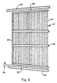
- the conventional basket wrap members extending radially on the outside of the top and bottom edges of each side of each basket are eliminated and replaced with tie barts which fasten the inner and outer end frames together and which extend radially above and below the heat exchange plates and which are located inside of the side boundaries of the heat exchange plates such that the plates extend all the way out to the side boundaries thereby reducing bypass gaps and increasing the volume of heat transfer surface in relation to the size of the basket.
- the lifting points are moved from the central region of the prior basket-wrapper structure to the inboard and outboard corners of the basket.
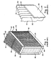
- FIGs 1 and 2 show a typical modular heat exchange basket 10 according to the prior art which comprises a basket-wrapper structure 12 inside of which are the individual heat exchange plates 14.
- the basket-wrapper structure 12 comprises a frame formed from inboard corner pieces 16, outboard corner pieces 18, inboard and outboard cross members 20 and 22 respectively and the radial top and bottom side members 24.
- the plates 14 are inside of this framework as shown in these Figures 1 and 2 and retained in position by the bars 26.
- Extending across the top of the baskets is rod 28 attached to the radial top side members 24 and to the bars 26. This rod 28 is usually located in vertical alignment with the center of gravity of the basket and serves as the lifting location for the basket.
- this lifting rod is attached to the upper members 24, the upper members must be substantial structural members in order to be able to support and lift the considerable weight of the entire basket. Therefore, these members 24 have a rather large cross section and, in particular, a rather large vertical dimension as shown most clearly in Figure 2 with these members 24 extending a substantial distance along the sides of the plates.
- FIG. 1 is a plan view of a small section through one sector-shaped compartment of a rotor showing a portion of a prior art basket module 10 according to U.S. Patent 5,485,877 in position between the rotor diaphragms 34.
- These basket modules are sized and shaped such that the angle of the sector is smaller than the complimentary angle of the basket whereby the outboard end of each basket contacts the diaphragms before the contact of the inboard end.
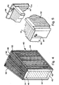
- the modular heat exchange basket 40 comprises a frame formed from the inboard corner pieces 42, outboard corner pieces 44 and inboard and outboard cross members 46 and 48 respectively. These frame members are all similar to the corresponding frame members of the prior art baskets as shown in Figures 1, 2 and 3.
- the basket 40 also has bars 50 which correspond to the bars 26 in Figure 1.
- the basket 40 does not have components equivalent to the radial top and bottom side members 24 or the lifting rod 28.
- the arrangement for lifting the basket is switched to the holes 54 located at each upper corner of the basket in the corner pieces 42. Holes 54 are also located at each lower corner for reversibility. This provides rigid points for lifting and eliminates the need for the structural rigidity of the basket wrapper structure of the prior art. The pressure between the piates created by packing the plates into the frame and the resulting friction between the plates will hold the plates in position and prevent them from slipping sideways.
- This basket design increases the heat transfer volume for a particular size rotor as well as decreasing the available flow-bypass gaps. The net result is increased thermal performance and the possible selection of a smaller, less expensive air preheater for a given application. Also, the manufacturing cost is lower than the prior art design.
Landscapes
- Engineering & Computer Science (AREA)
- Physics & Mathematics (AREA)
- Thermal Sciences (AREA)
- Mechanical Engineering (AREA)
- General Engineering & Computer Science (AREA)
- Heat-Exchange Devices With Radiators And Conduit Assemblies (AREA)
- Air Supply (AREA)
Claims (3)
- Wärmeübertragungselementkorbanordnung (40) für einen regenerativen Drehwärmetauscher, mit folgendem:a) einem Korbgrundrahmen, der einen inneren Endrahmen und einen äußeren Endrahmen enthält, wobei der innere und der äußere Endrahmen Eckteile (42, 44) enthalten, die Seitenränder des Korbgrundrahmens definieren;b) einem Stapel von mehreren Wärmetauschplatten (14), die nebeneinander zwischen dem inneren Endrahmen und dem äußeren Endrahmen gestapelt sind, wobei der Stapel von Wärmetauschplatten eine Oberkante, eine Unterkante und Seitenkanten (30) aufweist und wobei die Seitenkanten (30) des Stapels über die Seitenränder des Korbgrundrahmens hinausragen; undc) sich radial erstreckende horizontale Zugstäbe (52), die sich jeweils zwischen dem inneren Endrahmen und dem am äußeren Endrahmen befestigten anderen Ende erstrecken und ein daran befestigtes Ende aufweisen, wobei sich die Zustäbe (52) quer über die Ober- und Unterkante des Stapels erstrecken und neben den Seitenkanten (30) des Stapels und des Korbgrundrahmens, aber innerhalb davon, angeordnet sind, wobei die Seitenkanten (30) des Stapels über die Seitenränder des Korbgrundrahmens hinausragen.
- Wärmeübertragungselementkorbanordnung nach Anspruch 1 und weiterhin mit zusätzlichen Stäben (50), die den inneren Endrahmen mit den äußeren Endrahmen verbinden, sich quer über die Ober- und Unterkante des Stapels erstrecken und zwischen den Zugstäben (52) angeordnet sind.
- Wärmeübertragungselementkorbanordnung nach Anspruch 1 und weiterhin mit Hebestellen, die sich in den Eckteilen (42, 44) des inneren und des äußeren Endrahmens befinden.
Applications Claiming Priority (3)
| Application Number | Priority Date | Filing Date | Title |
|---|---|---|---|
| US08/969,601 US5893406A (en) | 1997-11-13 | 1997-11-13 | Regenerative heat exchanger |
| US969601 | 1997-11-13 | ||
| PCT/US1998/023501 WO1999026036A1 (en) | 1997-11-13 | 1998-11-04 | Rotary regenerative heat exchanger |
Publications (2)
| Publication Number | Publication Date |
|---|---|
| EP1031004A1 EP1031004A1 (de) | 2000-08-30 |
| EP1031004B1 true EP1031004B1 (de) | 2001-12-12 |
Family
ID=25515736
Family Applications (1)
| Application Number | Title | Priority Date | Filing Date |
|---|---|---|---|
| EP98956566A Expired - Lifetime EP1031004B1 (de) | 1997-11-13 | 1998-11-04 | Umlaufender regenerativer wärmetauscher |
Country Status (12)
| Country | Link |
|---|---|
| US (1) | US5893406A (de) |
| EP (1) | EP1031004B1 (de) |
| JP (1) | JP2001523808A (de) |
| KR (1) | KR20010031450A (de) |
| CN (1) | CN1278907A (de) |
| CA (1) | CA2306784A1 (de) |
| DE (1) | DE69802963T2 (de) |
| ES (1) | ES2169562T3 (de) |
| ID (1) | ID25545A (de) |
| PL (1) | PL340427A1 (de) |
| TW (1) | TW384371B (de) |
| WO (1) | WO1999026036A1 (de) |
Families Citing this family (5)
| Publication number | Priority date | Publication date | Assignee | Title |
|---|---|---|---|---|
| US6640880B1 (en) * | 2002-10-15 | 2003-11-04 | Alstom (Switzerland) Ltd | Heat exchanger recessed basket lifting cover |
| US7556085B2 (en) * | 2007-04-03 | 2009-07-07 | Alstom Technology Ltd | Reversible heat transfer element basket assembly with integrated frame for use in a heat exchanger |
| KR101004968B1 (ko) * | 2008-06-19 | 2011-01-04 | 사카팬코리아 주식회사 | 화력발전소용 열교환 엘리먼트 및 그의 제조방법 |
| US9683474B2 (en) | 2013-08-30 | 2017-06-20 | Dürr Systems Inc. | Block channel geometries and arrangements of thermal oxidizers |
| US20180031331A1 (en) * | 2016-07-26 | 2018-02-01 | Arvos, Inc. | Basket for heat transfer elements for a rotary air preheater |
Family Cites Families (12)
| Publication number | Priority date | Publication date | Assignee | Title |
|---|---|---|---|---|
| SE7710409L (sv) * | 1977-09-16 | 1979-03-17 | Wiking Lars | Paket innefattande en stapel av mot varandra anliggande, rektangulera platar avsett att anbringas i en regenerativ vermevexlare samt sett att tillverka ett sadant paket |
| US4552204A (en) * | 1983-12-01 | 1985-11-12 | The Air Preheater Company, Inc. | Means for lifting heating element baskets |
| US4557318A (en) * | 1983-12-01 | 1985-12-10 | The Air Preheater Company, Inc. | Means for lifting heating element baskets |
| US4561492A (en) * | 1985-01-22 | 1985-12-31 | The Air Preheater Company, Inc. | Element basket assembly for heat exchanger |
| US4606400A (en) * | 1985-06-13 | 1986-08-19 | The Air Preheater Company, Inc. | Element basket for heat exchanger |
| US4739822A (en) * | 1987-08-11 | 1988-04-26 | Combustion Engineering, Inc. | Low profile element basket assembly for heat exchanger |
| US4789024A (en) * | 1988-03-03 | 1988-12-06 | The Air Preheater Company, Inc. | Low profile element basket assembly with integral lifting means |
| US4838342A (en) * | 1988-06-01 | 1989-06-13 | The Air Preheater Company, Inc. | Element basket assembly for heat exchanger |
| US5048595A (en) * | 1991-03-04 | 1991-09-17 | Abb Air Preheater, Inc. | Rotary regenerative air preheater basket sealing |
| US5119885A (en) * | 1991-03-13 | 1992-06-09 | Abb Air Preheater, Inc. | Element basket for horizontal rotary regenerative heat exchanger |
| US5454418A (en) * | 1994-07-21 | 1995-10-03 | Abb Air Preheater, Inc. | Means for lifting heat transfer element baskets |
| US5485877A (en) * | 1994-10-28 | 1996-01-23 | Abb Air Preheater, Inc. | Rotary regenerative heat exchanger |
-
1997
- 1997-11-13 US US08/969,601 patent/US5893406A/en not_active Expired - Fee Related
-
1998
- 1998-10-29 TW TW087117978A patent/TW384371B/zh not_active IP Right Cessation
- 1998-11-04 DE DE69802963T patent/DE69802963T2/de not_active Expired - Fee Related
- 1998-11-04 ES ES98956566T patent/ES2169562T3/es not_active Expired - Lifetime
- 1998-11-04 PL PL98340427A patent/PL340427A1/xx unknown
- 1998-11-04 ID IDW20000849A patent/ID25545A/id unknown
- 1998-11-04 JP JP2000521357A patent/JP2001523808A/ja not_active Ceased
- 1998-11-04 CA CA002306784A patent/CA2306784A1/en not_active Abandoned
- 1998-11-04 KR KR1020007004482A patent/KR20010031450A/ko not_active Abandoned
- 1998-11-04 CN CN98811204A patent/CN1278907A/zh active Pending
- 1998-11-04 EP EP98956566A patent/EP1031004B1/de not_active Expired - Lifetime
- 1998-11-04 WO PCT/US1998/023501 patent/WO1999026036A1/en not_active Ceased
Also Published As
| Publication number | Publication date |
|---|---|
| CN1278907A (zh) | 2001-01-03 |
| JP2001523808A (ja) | 2001-11-27 |
| TW384371B (en) | 2000-03-11 |
| ID25545A (id) | 2000-10-12 |
| WO1999026036A1 (en) | 1999-05-27 |
| KR20010031450A (ko) | 2001-04-16 |
| DE69802963T2 (de) | 2002-08-29 |
| EP1031004A1 (de) | 2000-08-30 |
| ES2169562T3 (es) | 2002-07-01 |
| CA2306784A1 (en) | 1999-05-27 |
| PL340427A1 (en) | 2001-02-12 |
| DE69802963D1 (de) | 2002-01-24 |
| US5893406A (en) | 1999-04-13 |
Similar Documents
| Publication | Publication Date | Title |
|---|---|---|
| KR100307423B1 (ko) | 세미모듈로터구조를갖는공기예열기용로터제조방법 | |
| EP0372044B1 (de) | Wärmetauscher element | |
| EP1031004B1 (de) | Umlaufender regenerativer wärmetauscher | |
| US5836378A (en) | Air preheater adjustable basket sealing system | |
| US5740856A (en) | Rotary regenerative heat exchanger with multiple layer baskets | |
| JP2655523B2 (ja) | 回転再生式熱交換器 | |
| US5664620A (en) | Rotary regenerative heat exchanger | |
| CA2261731A1 (en) | Pre-stressed membrane basket cover assembly | |
| US5485877A (en) | Rotary regenerative heat exchanger | |
| KR20010087363A (ko) | 회전형 축열식 공기 예열기용 가열 부재 배스킷 조립체 | |
| US5803157A (en) | Semi-modular pinrack seal | |
| MXPA00004541A (en) | Rotary regenerative heat exchanger | |
| KR20010040840A (ko) | 회전형 재생 열 교환기 | |
| US5775405A (en) | Air preheater basket assembly | |
| AU723053C (en) | Method of fabricating a rotor for a rotary regenerative air preheater | |
| CZ20001649A3 (cs) | Rotační regenerační výměník tepla | |
| MXPA00007754A (en) | Rotary regenerative heat exchanger | |
| CZ288408B6 (en) | Process for producing rotor for a rotary regenerative air preheater |
Legal Events
| Date | Code | Title | Description |
|---|---|---|---|
| PUAI | Public reference made under article 153(3) epc to a published international application that has entered the european phase |
Free format text: ORIGINAL CODE: 0009012 |
|
| 17P | Request for examination filed |
Effective date: 20000403 |
|
| AK | Designated contracting states |
Kind code of ref document: A1 Designated state(s): DE ES FR GB IT SE |
|
| GRAG | Despatch of communication of intention to grant |
Free format text: ORIGINAL CODE: EPIDOS AGRA |
|
| 17Q | First examination report despatched |
Effective date: 20010410 |
|
| RAP1 | Party data changed (applicant data changed or rights of an application transferred) |
Owner name: ALSTOM POWER INC. |
|
| GRAG | Despatch of communication of intention to grant |
Free format text: ORIGINAL CODE: EPIDOS AGRA |
|
| GRAH | Despatch of communication of intention to grant a patent |
Free format text: ORIGINAL CODE: EPIDOS IGRA |
|
| GRAH | Despatch of communication of intention to grant a patent |
Free format text: ORIGINAL CODE: EPIDOS IGRA |
|
| GRAA | (expected) grant |
Free format text: ORIGINAL CODE: 0009210 |
|
| AK | Designated contracting states |
Kind code of ref document: B1 Designated state(s): DE ES FR GB IT SE |
|
| REG | Reference to a national code |
Ref country code: GB Ref legal event code: IF02 |
|
| REF | Corresponds to: |
Ref document number: 69802963 Country of ref document: DE Date of ref document: 20020124 |
|
| ET | Fr: translation filed | ||
| REG | Reference to a national code |
Ref country code: ES Ref legal event code: FG2A Ref document number: 2169562 Country of ref document: ES Kind code of ref document: T3 |
|
| PGFP | Annual fee paid to national office [announced via postgrant information from national office to epo] |
Ref country code: FR Payment date: 20020919 Year of fee payment: 5 |
|
| PGFP | Annual fee paid to national office [announced via postgrant information from national office to epo] |
Ref country code: DE Payment date: 20020920 Year of fee payment: 5 |
|
| PGFP | Annual fee paid to national office [announced via postgrant information from national office to epo] |
Ref country code: SE Payment date: 20020923 Year of fee payment: 5 Ref country code: GB Payment date: 20020923 Year of fee payment: 5 |
|
| PLBE | No opposition filed within time limit |
Free format text: ORIGINAL CODE: 0009261 |
|
| STAA | Information on the status of an ep patent application or granted ep patent |
Free format text: STATUS: NO OPPOSITION FILED WITHIN TIME LIMIT |
|
| PGFP | Annual fee paid to national office [announced via postgrant information from national office to epo] |
Ref country code: ES Payment date: 20021120 Year of fee payment: 5 |
|
| 26N | No opposition filed | ||
| PG25 | Lapsed in a contracting state [announced via postgrant information from national office to epo] |
Ref country code: GB Free format text: LAPSE BECAUSE OF NON-PAYMENT OF DUE FEES Effective date: 20031104 |
|
| PG25 | Lapsed in a contracting state [announced via postgrant information from national office to epo] |
Ref country code: SE Free format text: LAPSE BECAUSE OF NON-PAYMENT OF DUE FEES Effective date: 20031105 Ref country code: ES Free format text: LAPSE BECAUSE OF NON-PAYMENT OF DUE FEES Effective date: 20031105 |
|
| PG25 | Lapsed in a contracting state [announced via postgrant information from national office to epo] |
Ref country code: DE Free format text: LAPSE BECAUSE OF NON-PAYMENT OF DUE FEES Effective date: 20040602 |
|
| GBPC | Gb: european patent ceased through non-payment of renewal fee |
Effective date: 20031104 |
|
| EUG | Se: european patent has lapsed | ||
| PG25 | Lapsed in a contracting state [announced via postgrant information from national office to epo] |
Ref country code: FR Free format text: LAPSE BECAUSE OF NON-PAYMENT OF DUE FEES Effective date: 20040730 |
|
| REG | Reference to a national code |
Ref country code: FR Ref legal event code: ST |
|
| REG | Reference to a national code |
Ref country code: ES Ref legal event code: FD2A Effective date: 20031105 |
|
| PG25 | Lapsed in a contracting state [announced via postgrant information from national office to epo] |
Ref country code: IT Free format text: LAPSE BECAUSE OF NON-PAYMENT OF DUE FEES Effective date: 20051104 |