EP1030741B1 - System for coupling operating equipment to a washer - Google Patents
System for coupling operating equipment to a washer Download PDFInfo
- Publication number
- EP1030741B1 EP1030741B1 EP98957806A EP98957806A EP1030741B1 EP 1030741 B1 EP1030741 B1 EP 1030741B1 EP 98957806 A EP98957806 A EP 98957806A EP 98957806 A EP98957806 A EP 98957806A EP 1030741 B1 EP1030741 B1 EP 1030741B1
- Authority
- EP
- European Patent Office
- Prior art keywords
- cleaning fluid
- trolley
- washer
- washing chamber
- operating equipment
- Prior art date
- Legal status (The legal status is an assumption and is not a legal conclusion. Google has not performed a legal analysis and makes no representation as to the accuracy of the status listed.)
- Expired - Lifetime
Links
- 230000008878 coupling Effects 0.000 title claims description 26
- 238000010168 coupling process Methods 0.000 title claims description 26
- 238000005859 coupling reaction Methods 0.000 title claims description 26
- 239000012530 fluid Substances 0.000 claims description 55
- 238000005406 washing Methods 0.000 claims description 50
- 238000004140 cleaning Methods 0.000 claims description 43
- 230000008439 repair process Effects 0.000 claims description 13
- 239000007921 spray Substances 0.000 claims description 13
- 238000005086 pumping Methods 0.000 claims description 9
- 238000000034 method Methods 0.000 claims description 8
- XLYOFNOQVPJJNP-UHFFFAOYSA-N water Substances O XLYOFNOQVPJJNP-UHFFFAOYSA-N 0.000 claims description 8
- 239000002537 cosmetic Substances 0.000 claims description 4
- 238000010438 heat treatment Methods 0.000 claims description 3
- 238000005507 spraying Methods 0.000 claims description 3
- 239000007788 liquid Substances 0.000 claims 1
- 230000008901 benefit Effects 0.000 description 4
- 230000000249 desinfective effect Effects 0.000 description 4
- 241001465754 Metazoa Species 0.000 description 2
- 235000004443 Ricinus communis Nutrition 0.000 description 2
- 239000003599 detergent Substances 0.000 description 2
- 230000036541 health Effects 0.000 description 2
- 240000000528 Ricinus communis Species 0.000 description 1
- 239000010796 biological waste Substances 0.000 description 1
- 201000010099 disease Diseases 0.000 description 1
- 208000037265 diseases, disorders, signs and symptoms Diseases 0.000 description 1
- 230000007613 environmental effect Effects 0.000 description 1
- 210000003608 fece Anatomy 0.000 description 1
- 238000001914 filtration Methods 0.000 description 1
- 238000002347 injection Methods 0.000 description 1
- 239000007924 injection Substances 0.000 description 1
- 238000009434 installation Methods 0.000 description 1
- 235000019645 odor Nutrition 0.000 description 1
- 230000002572 peristaltic effect Effects 0.000 description 1
- 230000008569 process Effects 0.000 description 1
- 230000000153 supplemental effect Effects 0.000 description 1
- 210000002700 urine Anatomy 0.000 description 1
Images

Classifications
-
- B—PERFORMING OPERATIONS; TRANSPORTING
- B08—CLEANING
- B08B—CLEANING IN GENERAL; PREVENTION OF FOULING IN GENERAL
- B08B3/00—Cleaning by methods involving the use or presence of liquid or steam
- B08B3/02—Cleaning by the force of jets or sprays
Definitions
- the present invention relates to the system control arts. It finds particular application in conjunction with washing and disinfecting equipment and will be described with particular reference thereto. It should be appreciated, however, that the invention is also applicable to the control systems for other large scale pieces of equipment, particularly when a number of pieces of mechanical and electrical operating equipment located outside a housing are to be connected to the housing. Animal cages and associated racks are generally cleaned at frequent intervals to remove biological waste, such as urine, feces, and uneaten food. Similarly, large pieces of health care and scientific equipment, such as hospital beds, wheelchairs and carts are cleaned periodically. Thorough cleaning aids in preventing the spread of disease and reduces the development of unpleasant odors.
- Washers have been developed to handle the large scale cleaning and disinfecting of animal cages and racks and large pieces of scientific and health care equipment. Typically, these are large enough for a load of the cages or equipment to be wheeled manually into a washing chamber. Cleaning fluids are sprayed onto the load, usually under pressure and at elevated temperatures.
- the equipment is usually mounted on an outside wall of the chamber, with connections to the chamber being made through the chamber walls. For the typical washer, numerous such connections are made. Installing a new washer is a time consuming process, taking a week or more for the operating equipment to be mounted on the washing chamber and the connections made.
- the present system overcomes these problems and others.
- a washer in accordance with one aspect of the present invention, includes a stationary washing chamber which receives items to be washed. A plurality of spray nozzles are mounted in the washing chamber for washing the received items.
- the washer also includes operating equipment for operating the washer.
- the washer is characterized by a moveable trolley which supports the operating equipment for the washer.
- the operating equipment includes a first pump which supplies a cleaning fluid to the spray nozzles and a temperature booster for heating the cleaning fluid, the trolley being disposed adjacent an exterior wall of the washing chamber.
- Releasable couplings are provided for connecting the operating equipment to the washing chamber and for releasing the operating equipment for removing the operating equipment on the trolley to a repair area.
- a method for coupling operating equipment to a washer includes a washing chamber for receiving items to be washed and spray nozzles mounted in the washing chamber for spraying cleaning fluid on the received items in the washing chamber.
- the method is characterized by mounting the operating equipment to a moveable trolley, the operating equipment including pumping equipment for pumping cleaning fluid to the washing chamber for washing the items.
- the method further includes moving the trolley until it is adjacent an exterior wall of the washing chamber, connecting the operating equipment to the washing chamber with releasable couplings, and operating the washer with the operating equipment.
- This step includes pumping cleaning fluid from the trolley, through the releasable coupling to the spray nozzles, and washing the received items.
- One advantage of the present invention is that it enables the operating system to be connected to a washer or other controlled system in a short period of time.
- Another advantage of the present invention is that the operating equipment is easily uncoupled from the washing or other controlled system for repair or replacement of pieces of the operating equipment.
- Another advantage is that the operating system is readily transported to testing equipment and comprehensive repair facilities.
- the invention may take form in various components and arrangements of components, and in various steps and arrangements of steps.
- the drawings are only for purposes of illustrating a preferred embodiment and are not to be construed as limiting the invention.
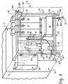
- FIGURE 1 is a schematic of a preferred embodiment of a washer according to the present invention.
- FIGURE 2 is a side view of the washer of FIGURE 1, with a coupled equipment trolley.
- a washer 1 includes an interior washing chamber 10.
- An exterior wall 12 encloses the chamber 10.
- a sump 16 is located beneath the washing chamber 10 and collects the used fluid as it drips down from the washing chamber.
- Operating equipment 20 disposed exterior to the washing chamber 10, supplies the cleaning fluid to the chamber, removes used fluid from the sump 16, and controls the operation of the spray nozzles 14 and other parts of the washer, such as doors, lights, and the like.
- the operating equipment is described with reference to a preferred embodiment. It is to be understood, however, that'the operating equipment may comprise any combination of pieces of equipment, supply vessels and the like, which for ease of access, or for other reasons, such as incompatibility with the washing chamber environment during a cleaning cycle, are disposed exterior to the chamber.
- the operating equipment 20 includes cleaning fluid tanks or vessels 22, which supply cleaning and disinfecting fluid to a first pump 24, through a fluid line or conduit 26.
- the pump 24 pumps the cleaning fluid to the spray nozzles 14.
- a sump pump 28 directs the used cleaning fluid from a sump outlet 29, extending from adjacent the bottom of the sump, to a filtration device 30 and the tanks 22 or to a drain 32, through a drain line 33. Before disposal, the fluid passes through a cool down vessel 34 where the temperature and pH of the fluid are adjusted to meet environmental standards.
- a detergent injection system 38 including metering pumps, such as peristaltic pumps 40, periodically supplies fresh concentrated cleaning and disinfecting fluids to the tanks 22 from supply containers 42 to maintain cleaning fluid concentration levels.
- a water inlet 46 supplies water to the tanks 22 to dilute the incoming concentrated fluid.
- the cleaning fluid is replenished at intervals by discarding a selected portion of the cleaning fluid that has circulated through the washing chamber 10.
- the tank is 'refilled with water and a supplemental charge of fresh detergent is added.
- a temperature booster 48 heats the cleaning fluid prior to reaching the nozzles.
- An electrical or electronic control circuit 50 regulates the operation of the operating equipment 20 and other parts of the washer, such as doors, a drier, and the like, according to the type of cleaning cycle selected.
- a moveable trolley 52 is located adjacent the exterior wall 12.
- the trolley includes a mounting frame assembly 54 for mounting the operating equipment 20 and wheels, castors or rollers 55 for wheeling the trolley around a facility in which the washing chamber is located.
- a mounting frame assembly 54 for mounting the operating equipment 20 and wheels, castors or rollers 55 for wheeling the trolley around a facility in which the washing chamber is located.
- castor locks are provided on the wheels.
- a trolley outlet 56 in fluid line 26 supplies fluid from the first pump 24 to the nozzles and a trolley inlet 57 receives used cleaning fluid from the sump 16.
- First and second releasable couplings, 58, 59 connected to the trolley outlet and inlet, respectively, and disposed exterior to the washing chamber 10, provide fluid connections between the operating equipment and the spray nozzles 14, and sump 16, respectively.
- a similar releasable coupling 60 also connects the water inlet 46 to a water supply, and another releasable coupling 62 connects the cooldown tank 34 with the drain 32.
- Each of the releasable couplings 58, 60, 62 includes first and second fittings, denoted A and B respectively.
- the first fitting 58A, 60A, 62A in each case, is disposed further from to the operating equipment 20 and releasably couples with the second fitting 58B, 60B, 62B, respectively.
- the trolley 52 when loaded with the operating equipment 20 is about one meter or less in width and about two meters or less in height so that the trolley passes easily through doors (not shown) of standard height and width in the facility.
- the operating equipment is preferably mounted to the trolley before leaving the factory, thereby reducing installation time.
- the operating equipment 20 When access to pieces of the operating equipment is required, such as when repairs are to be made, the operating equipment 20 is uncoupled from the washing chamber 10 by releasing the couplings 58.
- the couplings are of a quick-connecting type, allowing the couplings to be uncoupled or coupled in a short period of time.
- the trolley 52 is then wheeled a distance away from the washing chamber to provide access to the operating equipment 20 for repairs. If the trolley is to be moved to another site, electrical power is unplugged and the water inlet and drain are disconnected, by releasing releasable couplings 60 and 62. For more complex repairs, the trolley and mounted operating equipment is wheeled to a repair shop.
- some pieces of the operating equipment such as the control circuit 50, are mounted to the trolley frame 54 with hinges 64, which allow the pieces of operating equipment to swing away from the trolley, thereby providing access to other pieces of the operating equipment without uncoupling from the operating equipment.
- a removable access panel 70 optionally extends from a front wall 72 of the washer.
- the panel 70 shields the trolley and the operating equipment from view.
- the access panel includes a switch panel 74 which includes switches for operating the washer, such as for opening and closing doors, commencing a wash cycle, and the like. Electrical connections connect the switch panel with the control circuit 50.
- the switch panel is preferably removable from the access panel so that it can be transported with the trolley for repairs. Alternatively, the electrical connections are of a quick release type.
- the washer includes a cosmetic shell 76, which surrounds the trolley.
- the access panel provides a wall of the cosmetic shell. 'Other access openings are included in the shell as desired.
- solenoid valves 80 control the flow of fluid into and out of the cleaning fluid vessel and to a drain, respectively.
- the solenoid valves are mounted on the trolley and electrically connected with the electrical control circuit to be controlled thereby.
Landscapes
- Cleaning By Liquid Or Steam (AREA)
Description
Claims (10)
- A washer (1) comprising a stationary washing chamber (10) which receives items to be washed, a plurality of spray nozzles (14) mounted in the washing chamber for washing the received items, and operating equipment (20) for operating the washer, the washer characterized by:a moveable trolley (52) which supports the operating equipment (20) for the washer, the operating equipment including a first pump (24) which supplies a cleaning fluid to the spray nozzles and a temperature booster (48) for heating the cleaning fluid, the trolley being disposed adjacent an exterior wall (12) of the washing chamber;releasable couplings (58, 59, 60, 62) for connecting the operating equipment to the washing chamber and for releasing the operating equipment for removing the operating equipment on the trolley to a repair area.
- The washer of claim 1, further characterized by the trolley including wheels (55) for moving the trolley.
- The washer of either one of claims 1 and 2, further characterized by the trolley, when loaded with operating equipment, being about one meter wide or less and about two meters in height or less so that it passes easily through standard sized doors.
- The washer of any one of preceding claims 1, 2, and 3, wherein the washing chamber includes:a plurality of walls (12) which define the washing chamber (10);the plurality of nozzles (14) being mounted to the walls for spraying liquid into the washing chamber;a fluid conduit extending from the nozzles to a first fitting (58A) of a nozzle releasable coupling (58);a sump (16) disposed below the washing chamber for receiving fluid sprayed from the nozzles;a sump outlet (29) extending from adjacent the bottom of the sump to a first fitting (59B) of a second releasable coupling (59); and further characterized by:the trolley (52) including:a frame assembly (54) mounted on wheels or rollers (55);at least one cleaning fluid vessel (22) mounted to the trolley frame assembly;the first pump (24) being mounted to the trolley frame assembly and connected with the cleaning fluid vessel and a second fitting (58B) of the first releasable coupling (58) which is selectively connectable with and disconnectable from the first fitting (58A) of the first releasable coupling, the pump pumping cleaning fluid from the cleaning fluid vessel (22) to the nozzles (14); and,a sump pump (28) connected with the cleaning fluid vessel (22) and a second fitting (59A) of the second releasable coupling (59), the second fitting of the second releasable coupling being selectively connected with and disconnected from the first fitting (59B) of the second releasable coupling (59), the sump pump pumping cleaning fluid from the sump to the cleaning fluid vessel.
- The washer of claim 4, further characterized by:a cool down tank (34) mounted to the trolley frame, the cool down tank being fluidly connected with one of the sump pump (28) and the cleaning fluid vessel (22) for receiving spent cleaning fluid therefrom; and,a drain line (33) extending from the cool down tank for directing spent cleaning fluid from the cool down tank to a drain (32) for disposal.
- The washer of either one of claims 4 and 5, further characterized by:a supply container (42) of concentrated cleaner fluid mounted to the trolley frame assembly (54);a metering pump (40) connected with the supply container and the cleaning fluid vessel for selectively pumping metered quantities of concentrated cleaning fluid into the cleaning fluid vessel (22);a water inlet (46) for selectively suppling water to the cleaning fluid vessel (22); and,the temperature booster (48) being mounted to the trolley frame and connected between the first pump (24) and the second fitting (58B) of the first releasable coupling (58) for heating cleaning fluid in transit to the nozzles (14).
- The washer of claim 6, further characterized by:an electrical control circuit (50) mounted to the trolley frame assembly (54), the electrical control circuit being connected with the first pump (24), the sump pump (28), the metering pump (42), and the temperature booster (48) for controlling the operation thereof in accordance with a selected washing cycle.
- A method for coupling operating equipment (20) to a washer (1) which includes a washing chamber (10) for receiving items to be washed and spray nozzles (14) mounted in the washing chamber for spraying cleaning fluid on the received items in the washing chamber, the method characterized by:mounting the operating equipment to a moveable trolley (52), the operating equipment including pumping equipment for pumping cleaning fluid to the washing chamber for washing the items;moving the trolley until it is adjacent an exterior wall (12) of the washing chamber;connecting the operating equipment to the washing chamber with releasable couplings (58, 59, 60, 62); andoperating the washer with the operating equipment, including:pumping cleaning fluid from the trolley, through the releasable coupling to the spray nozzles, and washing the received items.
- The method of claim 8, further characterized by:disconnecting the operating equipment from the washing chamber (12) by releasing the couplings (58, 59, 60, 62); and,moving the trolley a distance away from the washing chamber for making repairs to the operating equipment.
- The method of either one of claims 8 and 9, further characterized by:the trolley being configured for being received in a cosmetic housing (76) of the washer.
Applications Claiming Priority (3)
| Application Number | Priority Date | Filing Date | Title |
|---|---|---|---|
| US970977 | 1997-11-14 | ||
| US08/970,977 US5964955A (en) | 1997-11-14 | 1997-11-14 | System for coupling operating equipment to a washer |
| PCT/US1998/024027 WO1999025490A1 (en) | 1997-11-14 | 1998-11-10 | System for coupling operating equipment to a washer |
Publications (2)
| Publication Number | Publication Date |
|---|---|
| EP1030741A1 EP1030741A1 (en) | 2000-08-30 |
| EP1030741B1 true EP1030741B1 (en) | 2002-09-11 |
Family
ID=25517777
Family Applications (1)
| Application Number | Title | Priority Date | Filing Date |
|---|---|---|---|
| EP98957806A Expired - Lifetime EP1030741B1 (en) | 1997-11-14 | 1998-11-10 | System for coupling operating equipment to a washer |
Country Status (5)
| Country | Link |
|---|---|
| US (1) | US5964955A (en) |
| EP (1) | EP1030741B1 (en) |
| DE (1) | DE69807919T2 (en) |
| ES (1) | ES2184339T3 (en) |
| WO (1) | WO1999025490A1 (en) |
Families Citing this family (5)
| Publication number | Priority date | Publication date | Assignee | Title |
|---|---|---|---|---|
| US7621285B2 (en) * | 2005-09-15 | 2009-11-24 | Steris Inc. | Tunnel washer system with improved cleaning efficiency |
| US7883624B2 (en) * | 2006-07-24 | 2011-02-08 | Steris Inc. | Self-cleaning filter for washers |
| ITMI20081189A1 (en) * | 2008-06-30 | 2010-01-01 | Rosauto Srl | WASHING DEVICE, EQUIPPED WITH WATER HEATING UNIT, FOR SPRAY GUNS AND THEIR COMPONENTS |
| ITUD20110182A1 (en) * | 2011-11-11 | 2013-05-12 | Steelco Spa | DEVICE FOR THE HYDRAULIC AND MECHANICAL CONNECTION OF AN OBJECT CARRIAGE TO BE WASHED AT A POWER SUPPLY CIRCUIT FOR A WASHING LIQUID FOR AN OBJECT WASHING MACHINE |
| IT201800010811A1 (en) * | 2018-12-05 | 2020-06-05 | Iwt Srl | Liquid waste treatment system, adapted for application in a continuous Tunnel washing machine for the Preclinical Pharmaceutical Research sector |
Family Cites Families (15)
| Publication number | Priority date | Publication date | Assignee | Title |
|---|---|---|---|---|
| US2448045A (en) * | 1945-07-06 | 1948-08-31 | Westinghouse Electric Corp | Electrical cleaning means |
| US3195546A (en) * | 1964-01-22 | 1965-07-20 | Associated Testing Lab Inc | Vehicle washing unit |
| DE6911912U (en) * | 1969-03-25 | 1969-07-17 | Burger Eisenwerke Ag | CLEANING DEVICE FOR ROASTING, BAKING AND DEFROSTING |
| US4402331A (en) * | 1981-03-27 | 1983-09-06 | Delta Manufacturing And Sales, Inc. | Portable lavage device |
| US4559960A (en) * | 1983-10-20 | 1985-12-24 | City Of Albany, Georgia | Sewer cleaner apparatus |
| US4637413A (en) * | 1984-07-09 | 1987-01-20 | Safety-Kleen Corporation | Degreasing apparatus |
| US4653518A (en) * | 1985-07-23 | 1987-03-31 | Shiro Adachi | Washing apparatus for containers used to hold urine |
| US4650456A (en) * | 1985-10-30 | 1987-03-17 | Ranpak Corp. | Mechanism for producing pad-like cushioning dunnage product from sheet material with separate stock roll cart |
| US4911188A (en) * | 1988-03-02 | 1990-03-27 | Midwest Hydro-Blasting, Inc. | Hydraulic ceiling-concrete remover |
| DE8816334U1 (en) * | 1988-08-18 | 1989-10-05 | Hobart AG, 7600 Offenburg | Device for cleaning serving trolleys etc. |
| US5016314A (en) * | 1989-09-28 | 1991-05-21 | Envirestore Technologies, Inc. | Asbestos-containing materials removal assembly |
| US5067504A (en) * | 1990-11-21 | 1991-11-26 | Coleman Iii Seab H | Asbestos collection and containment device |
| US5289837A (en) * | 1992-12-09 | 1994-03-01 | Eduardo Betancourt | Engine cleaning system |
| US5390636A (en) * | 1994-02-14 | 1995-02-21 | Wynn Oil Company | Coolant transfer apparatus and method, for engine/radiator cooling system |
| US5657781A (en) * | 1995-10-10 | 1997-08-19 | Circle S, Inc. | Machine for cleaning rollers in paper producing machines in situ |
-
1997
- 1997-11-14 US US08/970,977 patent/US5964955A/en not_active Expired - Lifetime
-
1998
- 1998-11-10 WO PCT/US1998/024027 patent/WO1999025490A1/en not_active Ceased
- 1998-11-10 DE DE69807919T patent/DE69807919T2/en not_active Expired - Lifetime
- 1998-11-10 ES ES98957806T patent/ES2184339T3/en not_active Expired - Lifetime
- 1998-11-10 EP EP98957806A patent/EP1030741B1/en not_active Expired - Lifetime
Also Published As
| Publication number | Publication date |
|---|---|
| ES2184339T3 (en) | 2003-04-01 |
| DE69807919T2 (en) | 2003-05-28 |
| DE69807919D1 (en) | 2002-10-17 |
| EP1030741A1 (en) | 2000-08-30 |
| WO1999025490A1 (en) | 1999-05-27 |
| US5964955A (en) | 1999-10-12 |
Similar Documents
| Publication | Publication Date | Title |
|---|---|---|
| US5702536A (en) | Method of cleaning a patient support device for care, maintenance, and treatment of the patient | |
| US5993739A (en) | Continuous washing system | |
| US5983908A (en) | Glass washing and dishwashing machine | |
| US6341612B1 (en) | Two compartment container for neutralizing used cleaning solutions | |
| WO2007147538A1 (en) | Inlet device for disinfection apparatus and method for liquid transfer | |
| CN114532953B (en) | Endoscope cleaning device | |
| US8388763B2 (en) | Portable washing and disinfecting apparatus | |
| US4073663A (en) | Method and apparatus for automatic bacteriological cleaning and disinfection of objects | |
| US6257254B1 (en) | Cleaning system for a washer | |
| US5964955A (en) | System for coupling operating equipment to a washer | |
| CA2030460C (en) | Washing apparatus | |
| US6550487B1 (en) | Apparatus for removing deposits from enclosed chambers | |
| AU2006246037B2 (en) | Process and system for the disposal of excretion containers | |
| CA2539401C (en) | Milk pump system | |
| JPH09299897A (en) | Container washing/drying device and washing/drying of container by this device | |
| CN215082694U (en) | Robot drip washing disinfection system | |
| KR100273204B1 (en) | Filter cleaning apparatus for wet-station | |
| NZ194295A (en) | Flusher disinfector steam supply | |
| JP4043769B2 (en) | Tank cleaning apparatus and cleaning method | |
| CN111549482B (en) | Clothes treatment equipment with humidifying function and control method thereof | |
| CN117206245B (en) | A workpiece cleaning and disinfection device and its control method | |
| CA2530648A1 (en) | Device in the form of a washing machine comprising a bioreactor for cleaning machine parts that are soiled with oil and fat | |
| CN121588523A (en) | A solid particle separation and recovery system and method | |
| JP3864410B6 (en) | Glass cleaning cooling device | |
| CN112870414A (en) | Robotic spraying and washing system |
Legal Events
| Date | Code | Title | Description |
|---|---|---|---|
| PUAI | Public reference made under article 153(3) epc to a published international application that has entered the european phase |
Free format text: ORIGINAL CODE: 0009012 |
|
| 17P | Request for examination filed |
Effective date: 20000509 |
|
| AK | Designated contracting states |
Kind code of ref document: A1 Designated state(s): DE ES FI GB IE IT SE |
|
| RIN1 | Information on inventor provided before grant (corrected) |
Inventor name: THIBAULT, NATHALIE Inventor name: PARENT, GHISLAIN Inventor name: DUCHAINE, MARIO Inventor name: EDMOND, MICHEL Inventor name: THERIAULT, YVES-ANDRE Inventor name: LEMAY, MICHEL Inventor name: ROCHETTE, DANIEL |
|
| 17Q | First examination report despatched |
Effective date: 20010621 |
|
| GRAG | Despatch of communication of intention to grant |
Free format text: ORIGINAL CODE: EPIDOS AGRA |
|
| GRAG | Despatch of communication of intention to grant |
Free format text: ORIGINAL CODE: EPIDOS AGRA |
|
| GRAH | Despatch of communication of intention to grant a patent |
Free format text: ORIGINAL CODE: EPIDOS IGRA |
|
| GRAH | Despatch of communication of intention to grant a patent |
Free format text: ORIGINAL CODE: EPIDOS IGRA |
|
| GRAA | (expected) grant |
Free format text: ORIGINAL CODE: 0009210 |
|
| AK | Designated contracting states |
Kind code of ref document: B1 Designated state(s): DE ES FI GB IE IT SE |
|
| REG | Reference to a national code |
Ref country code: GB Ref legal event code: FG4D |
|
| REG | Reference to a national code |
Ref country code: IE Ref legal event code: FG4D |
|
| REF | Corresponds to: |
Ref document number: 69807919 Country of ref document: DE Date of ref document: 20021017 |
|
| REG | Reference to a national code |
Ref country code: ES Ref legal event code: FG2A Ref document number: 2184339 Country of ref document: ES Kind code of ref document: T3 |
|
| PLBE | No opposition filed within time limit |
Free format text: ORIGINAL CODE: 0009261 |
|
| STAA | Information on the status of an ep patent application or granted ep patent |
Free format text: STATUS: NO OPPOSITION FILED WITHIN TIME LIMIT |
|
| 26N | No opposition filed |
Effective date: 20030612 |
|
| PGFP | Annual fee paid to national office [announced via postgrant information from national office to epo] |
Ref country code: FI Payment date: 20071129 Year of fee payment: 10 |
|
| PGFP | Annual fee paid to national office [announced via postgrant information from national office to epo] |
Ref country code: SE Payment date: 20071128 Year of fee payment: 10 |
|
| EUG | Se: european patent has lapsed | ||
| PG25 | Lapsed in a contracting state [announced via postgrant information from national office to epo] |
Ref country code: FI Free format text: LAPSE BECAUSE OF NON-PAYMENT OF DUE FEES Effective date: 20081110 |
|
| REG | Reference to a national code |
Ref country code: IE Ref legal event code: MM4A |
|
| PGFP | Annual fee paid to national office [announced via postgrant information from national office to epo] |
Ref country code: IE Payment date: 20071126 Year of fee payment: 10 |
|
| PG25 | Lapsed in a contracting state [announced via postgrant information from national office to epo] |
Ref country code: IE Free format text: LAPSE BECAUSE OF NON-PAYMENT OF DUE FEES Effective date: 20081110 |
|
| PG25 | Lapsed in a contracting state [announced via postgrant information from national office to epo] |
Ref country code: SE Free format text: LAPSE BECAUSE OF NON-PAYMENT OF DUE FEES Effective date: 20081111 |
|
| PGFP | Annual fee paid to national office [announced via postgrant information from national office to epo] |
Ref country code: DE Payment date: 20171129 Year of fee payment: 20 |
|
| PGFP | Annual fee paid to national office [announced via postgrant information from national office to epo] |
Ref country code: GB Payment date: 20171127 Year of fee payment: 20 Ref country code: ES Payment date: 20171201 Year of fee payment: 20 Ref country code: IT Payment date: 20171123 Year of fee payment: 20 |
|
| REG | Reference to a national code |
Ref country code: DE Ref legal event code: R071 Ref document number: 69807919 Country of ref document: DE |
|
| REG | Reference to a national code |
Ref country code: GB Ref legal event code: PE20 Expiry date: 20181109 |
|
| PG25 | Lapsed in a contracting state [announced via postgrant information from national office to epo] |
Ref country code: GB Free format text: LAPSE BECAUSE OF EXPIRATION OF PROTECTION Effective date: 20181109 |
|
| REG | Reference to a national code |
Ref country code: ES Ref legal event code: FD2A Effective date: 20200803 |
|
| PG25 | Lapsed in a contracting state [announced via postgrant information from national office to epo] |
Ref country code: ES Free format text: LAPSE BECAUSE OF EXPIRATION OF PROTECTION Effective date: 20181111 |