EP1030622B2 - Threaded implant for obtaining reliable anchoring in bone - Google Patents
Threaded implant for obtaining reliable anchoring in bone Download PDFInfo
- Publication number
- EP1030622B2 EP1030622B2 EP98951904.6A EP98951904A EP1030622B2 EP 1030622 B2 EP1030622 B2 EP 1030622B2 EP 98951904 A EP98951904 A EP 98951904A EP 1030622 B2 EP1030622 B2 EP 1030622B2
- Authority
- EP
- European Patent Office
- Prior art keywords
- implant
- thread
- bone
- threading
- threaded
- Prior art date
- Legal status (The legal status is an assumption and is not a legal conclusion. Google has not performed a legal analysis and makes no representation as to the accuracy of the status listed.)
- Expired - Lifetime
Links
Images


Classifications
-
- A—HUMAN NECESSITIES
- A61—MEDICAL OR VETERINARY SCIENCE; HYGIENE
- A61C—DENTISTRY; APPARATUS OR METHODS FOR ORAL OR DENTAL HYGIENE
- A61C8/00—Means to be fixed to the jaw-bone for consolidating natural teeth or for fixing dental prostheses thereon; Dental implants; Implanting tools
- A61C8/0018—Means to be fixed to the jaw-bone for consolidating natural teeth or for fixing dental prostheses thereon; Dental implants; Implanting tools characterised by the shape
- A61C8/0022—Self-screwing
- A61C8/0025—Self-screwing with multiple threads
-
- A—HUMAN NECESSITIES
- A61—MEDICAL OR VETERINARY SCIENCE; HYGIENE
- A61C—DENTISTRY; APPARATUS OR METHODS FOR ORAL OR DENTAL HYGIENE
- A61C8/00—Means to be fixed to the jaw-bone for consolidating natural teeth or for fixing dental prostheses thereon; Dental implants; Implanting tools
- A61C8/0018—Means to be fixed to the jaw-bone for consolidating natural teeth or for fixing dental prostheses thereon; Dental implants; Implanting tools characterised by the shape
- A61C8/0022—Self-screwing
-
- A—HUMAN NECESSITIES
- A61—MEDICAL OR VETERINARY SCIENCE; HYGIENE
- A61C—DENTISTRY; APPARATUS OR METHODS FOR ORAL OR DENTAL HYGIENE
- A61C8/00—Means to be fixed to the jaw-bone for consolidating natural teeth or for fixing dental prostheses thereon; Dental implants; Implanting tools
- A61C8/0048—Connecting the upper structure to the implant, e.g. bridging bars
- A61C8/005—Connecting devices for joining an upper structure with an implant member, e.g. spacers
- A61C8/0068—Connecting devices for joining an upper structure with an implant member, e.g. spacers with an additional screw
-
- A—HUMAN NECESSITIES
- A61—MEDICAL OR VETERINARY SCIENCE; HYGIENE
- A61C—DENTISTRY; APPARATUS OR METHODS FOR ORAL OR DENTAL HYGIENE
- A61C8/00—Means to be fixed to the jaw-bone for consolidating natural teeth or for fixing dental prostheses thereon; Dental implants; Implanting tools
- A61C8/0089—Implanting tools or instruments
Definitions
- the present invention relates to a threaded implant for obtaining reliable anchoring in bone, preferably jaw-bone, in the human body.
- the bone in question is in this case provided with a hole in whose side wall it is possible to establish an internal threading which can cooperate with an external threading on the implant for reliable anchoring and healing-in of the implant in the bone substance.
- Implants with threads for example self-tapping threads, for insertion/screwing into holes made in the bone/jaw-bone are available in large numbers and designs on the open market and are described in the patent literature. Thus, for example, reference may be made to Swedish Patent Application 9603091-7 filed by the same Applicant filing the present patent application.
- Some of the threaded implants are cylindrical, while others can have the said conical designs in order to imitate the tooth root which they are intended to replace.
- the implants are inserted into holes that have been drilled beforehand in the jaw bone.
- a cylindrical hole is drilled for cylindrical implants, and for conical implants a conical hole is prepared.
- the cited method using the Branemark System® involves securing screw-shaped implants in the jaw bone. After a period of healing-in, normally about 3 - 6 months, the bone has grown in direct contact with the implant and the latter can then be used to support a prosthetic reconstruction. This is in most cases achieved by means of a so-called spacer element being attached to the implant, which can be done by a screw connection. A transfer cap is then attached to the top of the spacer upon so-called impression-taking, and the finished prosthetic reconstruction can thereafter be applied to the spacer.
- the purpose of the non-circularity is to reduce the friction between bone and implant on insertion of the implant. This is important mainly in the case of hard bone.
- US 5,427,527 discloses a threaded implant for anchoring in bone substance in the human body.
- the external threading on the implant can cooperate with the side wall of a hole in the bone substance.
- the implant threading has a taper of between about 1° and 3°, or 2°. The threading and the conicity extend along most of the length of the implant.
- the object of the present invention is to solve the above problems among others.
- the holes and recesses are situated at the very front of the tip where in most cases the quality of the bone (its hardness) is poor.
- the holes and recesses reduce the threaded area of the implant. It must be emphasized here that it is essential to have the greatest possible threaded area for effective transfer of the functional load from the tooth prosthesis or tooth bridge down to the bone. This applies in particular in the case of soft bone.
- An important precondition for being able to implement the abovementioned methods is to create the conditions for obtaining direct bone contact with the implant during the healing-in process. It is essential in this connection to perform meticulous surgery when fitting the implants. The hole for the implant must be drilled with great precision and in this connection it is of the utmost importance that the temperature in the bone does not become too high. These requirements have hitherto _meant that both the drilling and the fitting of the implant have been carried out with the hole-forming and tightening instruments being operated at low speed. The speed of rotation which is normally employed when fitting implants is 20 - 25 rpm. This means that the time required for fitting an implant can amount to 1 minute or more.
- the invention is intended to solve the last-mentioned problems too.
- the implant threading has a gradually increasing diameter as seen from the tip of the implant to ensure that the pressure between the bone substance and the implant has essentially a constant or only slightly increasing value during the greater part of the operation of screwing the implant in.
- the implant threading also comprises a portion whose thread has a slight conical narrowing towards the free end or tip of the implant and extends along at least the greater part of the length of the implant.
- the front portion or tip of the implant is designed with a conical thread which has a stronger conicity than the other thread or thread parts of the implant.
- the conicity measured over the diameter of the slightly conical thread can be chosen within the range of 0.1 to 0.4 mm or can have an angle of inclination of about 0.5 - 2°.
- the thread conicity of the thread of the front portion or tip can be of the order of 0.4 - 0.8 mm or can be designed with an angle of inclination of about 10 - 15°.
- the tip can have a height which is 10 - 30% of the height of the slightly conical portion the implant.
- the implant is used in a circular cylindrical hole in the bone.
- a non-circularity or eccentricity is intended to substantially increase the rotational stability of the implant in the recently inserted (initial) state or the incorporated state of the implant.
- the non-circularity or eccentricity can also be provided to counteract the breaking up of the thread at the inner parts of the hole.
- the implant is arranged with a minimum diameter or cross-sectional width which corresponds to or is only slightly greater, for example 1 - 5%.greater, than the diameter of the hole in the bone/jaw-bone.
- the minimum diameter of the implant is understood to mean the root diameter of the thread at the minimum diameter of the slightly conical portion.
- the tip or free end of the implant has a circular or concentric thread which, seen from the free end, merges gradually into a non-circular or eccentric thread on the remaining part or parts of the implant.
- the non-circularity is provided to ensure that there are no sharp corners, but only bevelled corners.
- the non-circularity can also be provided so that areas of maximum diameter are displaced in the peripheral direction from one thread turn to the next thread turn.
- the non-circularity can be provided on the thread-supporting body and/or on the outer portion of each thread.
- Embodiments comprising the features above counteract deformation or breaking-up of free bone trabeculae which surround the hole in the bone.
- the number of thread spirals can be chosen as a function of the desired time for screwing the implant into the hole and thus, for example, the number of thread spirals can be two, three or four.
- the number of thread spirals is adapted to the number of cutting edges on the implant so that symmetrical cutting forces are obtained.
- implants are obtained which have very good properties.
- the implant can be provided with substantially improved starting properties, which mean that the implant easily "takes threads", even if the initial hole made in the bone is small in relation to the diameter of the implant. Because the pressure between the implant and the thread in the bone does not fall, this permits a gradually increasing advancing force which counteracts any tendency towards breaking the sometimes brittle threads in the bone.
- the initial stability of the implant in the hole can be improved since the elasticity of the bone means that the bone tissue can completely or partially spring back into the shallower portions of the fixture.
- the implant thread can be designed with cross sections which are shaped as polygons, preferably with rounded corners, or with 3-sided, 5-sided or 7-sided geometry. This type of non-circular geometry has the property that it has an apparently considerably constant diameter when measured by sliding calliper or micrometer.
- the implant can be provided with thread cutters. These can be arranged so that they cut at the greatest diameter of the implant, which can be expedient when the implant is conical and the conicity affords a clamping effect.
- Non-circularity can be such that the base diameter gradually increases, or, alternatively, the non-circularity increases in conjunction with a constant or only slightly increasing "internal diameter".
- the combination of non-circularity and conicity means that because of the pressure between bone tissue and implant the bone springs into the shallower parts of the implant.
- Non-circular cylindrical implants by contrast, have a reduced pressure and reduced initial stability in soft bone because the pressure and resilience decrease.
- the pitch can be increased and, in this way, the time for tightening the implant can be shortened.
- reference number 1 designates jaw-bone.
- a circular hole 2 has been made in the jaw-bone.
- the hole can be made in a manner known per se using equipment known per se.
- An implant with threads of different conicities can be applied to the hole.
- Parts of the said implant are represented by parts of the free end 3 of the implant.
- the said free end has a tip part 3a which merges into a part 3b.
- the latter part has a thread 3d which has a slight conicity.
- Slight conicity is understood here as meaning conicities in which an angle of inclination ⁇ is of the order of 1° in relation to a vertical axis 2a of the hole 2 or an axis parallel to this axis.
- the tip 3a is provided with a thread 3e which is arranged with a conicity which gives an angle ⁇ of the order of 10°.
- the entry surface or entry part of the tip 3a has a diameter D' which essentially corresponds to the diameter d of the hole or slightly exceeds the said diameter d.
- the hole diameter d can also be chosen as a function of the softness of the bone (quality).
- the upper and lower parts of the hole are indicated by 2c and 2d.
- FIG. 2 shows a structural design of the implant 3 with associated thread 3d'.
- the implant has been screwed fully into the hole 2' in the jaw-bone and, on being screwed in, has created a thread 1a in the wall of the hole in the jaw-bone or the side wall 2b of the hole 2'.
- the implant has securing members/spacer members 4 for a special tooth replacement, tooth prosthesis, etc. (not shown).
- the member 4 can be provided with a flange 4a with which it is possible to define the final degree of threading of the implant so that optimum thread is exposed to the jaw-bone.
- the implant is in this case provided with cutting edges 5, of a type known per se, at the said tip 3a'.
- the tip part 3a' has a height h which represents 20 - 30% of the total height H of the threaded part of the implant.
- FIG 3 shows the implant according to Figure 2 in vertical section.
- a threaded recess 6 is shown whose internal thread has been labelled 6a.
- the said spacer arrangement 4 according to Figure 2 can be screwed into the said internal thread in a manner known per se.
- Figure 4 shows that, at the said free end, the implant according to Figures 2 and 3 is designed with cutting edges known per se, which in Figure 4 have been labelled 5a, 5b, 5c and 5d.
- Figure 5 shows that the chosen conicity for the thread 3d' (cf. Figure 1 ) pushes the jaw-bone substance 1" out in radial directions R.
- the conicity of the thread 3d' and the thread diameter GD of the inclined thread are in this case chosen such that the contact pressure P, P' is of essentially the same order or only slightly increases as the implant 3' is being screwed in a direction 7 into the jaw-bone 1" (the hole made in it).
- the thread 3d/3d' can be designed with a non-circular/eccentric thread cross-section and/or with a non-circular cross-section for the thread-bearing body.
- Figures 6, 7 and 8 show different types of non-circularity and positions of rotation of the various thread cross-sections.
- the individual thread cross-sections can also have different non-circularity.
- the thread at the tip or free end of the implant can have a circular or concentric thread cross-section which at the top merges into a non-circular thread cross-section according to Figures 6 - 8 . In this way it is possible to achieve a considerable freedom from wobble during tightening.
- one thread is indicated by 8.
- the thread has a number of depressions 8a, 8b, 8c and 8d.
- the parts effecting the threads in the jaw-bone with the greatest radial dimensions are indicated by 8e, 8f, 8g, 8h and 8i.
- the characteristic of these protruding parts is that they do not have sharp corners, i.e. they have parts which are arcuate in cross-section. This applies also in the case of a non-circular thread-bearing body.
- the number of protrusions and depressions can vary from that indicated in Figure 6 , cf. Figures 7 and 8.
- Figure 9 shows the case in which the implant has a circular or concentric thread 9 at the tip.
- Figures 11 and 12 are intended to show so-called multiple thread entries or multiple thread spirals which, depending on the number of entries and spirals, provide different pitches, compare with Figure 10 which shows a design with a single thread entry and thread spiral.
- Figure 11 shows an embodiment with two thread entries or thread spirals which provide a pitch indicated by Ph', compare with the pitch Ph in Figure 10 .
- double thread spirals is already well known per se, it will not be described in detail here. The principle is already known from completely different areas and for solving completely different problems. In this connection reference may be made to worm gears which use worm screws with multiple thread entries or thread spirals. The principle is also known in a so-called open spiral implant, see EP-A-263809 .
- Figure 12 shows an embodiment with three thread entries or thread spirals which provide a pitch Ph".
- the number of thread-entries/thread spirals can be combined with a number of cutting edges (cf. Figure 4, 5a, 5b, 5c, 5d ) so that symmetrical or balanced forces are obtained, i.e. the forces balance each other out. Compare also with the above.
- the insertion time can be shortened in the case of implants which are designed with multiple thread entries.
- a shortened fitting time also reduces the expensive operating time, especially when fitting long and numerous implants. For example, when fitting six implants measuring 18 mm in length, which is not unusual in a so-called whole-jaw operation, 5 minutes of operating time are saved if two thread entries are used instead of one. Moreover, if the hole needs to be pre-threaded, then the saving in time is threefold.
- Figure 13 shows an embodiment of the implant in which the non-circularity of the various thread cross-sections is displaced along the longitudinal direction L of the implant.
- Each thread 10 is displaced in relation to the adjacent thread 11 in the direction of rotation.
- the abovementioned bevelled corners are in this case indicated by 12.
- the wobble freedom on insertion of the implant into the hole in the bone with an instrument can in this way be further increased, i.e. improved rotational stability is obtained. Fitting is quicker and simpler.
- Some of the abovementioned embodiments can be used as soft-bone fixtures.
- the invention can also be used in cases where the fitting is to be done with the aid of thread taps (i.e. in two stages).
- Figure 14 shows a complete implant with displaced non-circularity according to Figure 13 and a threaded tip part 13.
- Figure 15 shows an illustrative embodiment in which the non-circularity between the different thread turns is not displaced.
- Figure 16 shows the relationship for the chosen slight conicity and the hole diameter Hd for a hole 15 drilled in the jaw-bone 14.
- the chosen values a and b for the conicity of the body 16 can be about 0.55 mm and 0.45 mm, respectively.
- the constant or essentially constant mutual pressures (cf. P and P') can be achieved in this way.
- the conicity can be obtained either by means of the diameter of the whole thread profile gradually increasing as seen from the tip, or by means of the bottom diameter of the thread or its external diameter gradually increasing.
- Figure 17 shows a concrete threading 17, 18 in the jaw-bone 19 with the aid of the fixture 20.
- Figure 18 shows the insertion moment as a function of the insertion depth, on the one hand for slightly conical implants and on the other hand for cylindrical implants. Since the pressure does not decrease during the insertion procedure and acts on an increasingly greater area of the implant, this means that the slightly conical implant requires an increasingly greater insertion moment, as can be seen from the figure. The greater insertion moment is a measure of the increased stability of the implant. Cylindrical implants have insertion curves with a constant or even. decreasing moment, especially in the case of poor bone quality, as can also be seen from Figure 18 .
Abstract
Description
- The present invention relates to a threaded implant for obtaining reliable anchoring in bone, preferably jaw-bone, in the human body. The bone in question is in this case provided with a hole in whose side wall it is possible to establish an internal threading which can cooperate with an external threading on the implant for reliable anchoring and healing-in of the implant in the bone substance.
- Implants with threads, for example self-tapping threads, for insertion/screwing into holes made in the bone/jaw-bone are available in large numbers and designs on the open market and are described in the patent literature. Thus, for example, reference may be made to Swedish Patent Application
9603091-7 - In this connection it is known to use different thread formations on implants. Thus, for example, it is already known to use implants with cone-shaped threads and to choose different conicities on one and the same implant. The methods for forming the holes in the bone/jaw-bone are also already well known. In this connection, reference may be made, in purely general terms, to dental treatment by the Branemark System®.
- Some of the threaded implants are cylindrical, while others can have the said conical designs in order to imitate the tooth root which they are intended to replace. The implants are inserted into holes that have been drilled beforehand in the jaw bone. A cylindrical hole is drilled for cylindrical implants, and for conical implants a conical hole is prepared. The cited method using the Branemark System® involves securing screw-shaped implants in the jaw bone. After a period of healing-in, normally about 3 - 6 months, the bone has grown in direct contact with the implant and the latter can then be used to support a prosthetic reconstruction. This is in most cases achieved by means of a so-called spacer element being attached to the implant, which can be done by a screw connection. A transfer cap is then attached to the top of the spacer upon so-called impression-taking, and the finished prosthetic reconstruction can thereafter be applied to the spacer.
- From the known methods it is already known that good long-term results are obtained if the osteointegration between the bone and the implant can take place with a tight profile and small pitch of the threads in question. During the osteointegration, the bone tissue grows in direct contact with the implant. Upon fitting the implants, the said holes are drilled in the bone with great precision. In this connection it is already known to use tightening instruments which rotate at about 20 - 25 rpm.
- In
WO-A1-9725933 WO-A1-9306786 - In
WO 97/25933 PCT/US97/00332 - The purpose of the non-circularity is to reduce the friction between bone and implant on insertion of the implant. This is important mainly in the case of hard bone.
-
US 5,427,527 discloses a threaded implant for anchoring in bone substance in the human body. The external threading on the implant can cooperate with the side wall of a hole in the bone substance. The implant threading has a taper of between about 1° and 3°, or 2°. The threading and the conicity extend along most of the length of the implant. - The problem with using cylindrical implants in cylindrical holes is that the thread which is in most cases created by the self-tapping tip of the implant is worn away as the implant is screwed in, and with this wearing the thread is widened, mainly at the inlet/mouth of the hole in the bone. This results in the implant having a slightly loose anchoring, especially in weak/soft bone, which means that the implant has a poor initial stability. When using conical implants with a conical preparation, one of the greatest problems is the development of heat which occurs during the conical preparation. Since a conical drill cuts along the whole periphery, relatively great heat is generated, and this negative effect is amplified further by the fact that the cutting geometry of a conical drill becomes worse because a low surface pressure occurs at the periphery of the conical drill. This means that the drill cannot cut proper chips but instead scrapes bone away, and this has a high heat-generating effect. This heat can damage the bone and can lead to the bone nearest the drilled hole dying. This drastically reduces the possibilities of successful osteointegration. The object of the present invention is to solve the above problems among others.
- The said use of a screw connection on the implant involves the screwing and unscrewing of screws. This represents a relatively great risk since the implant is subjected to breaking stresses which mean that the implant is at risk of being turned out of its position. This applies in particular if the implants are fitted in bone which is of weak/soft quality. The above unscrewing problems are especially pronounced in the case of implants with a thread which is circularly symmetrical. In most threaded implants, it is of course possible to arrange cutouts at the tip, which are intended both to cut threads and to contribute to the rotational stability. There are also implants with transverse holes for bone to grow into. A common feature of these known constructions is that the recesses and holes are relatively small when seen in relation to the threaded area of the implant. Since the surface of the recesses or holes is small, deformation or break-up of the ingrown bone can easily take place upon torsional loading. In addition, the holes and recesses are situated at the very front of the tip where in most cases the quality of the bone (its hardness) is poor. There is also an inherent weakness in that the holes and recesses reduce the threaded area of the implant. It must be emphasized here that it is essential to have the greatest possible threaded area for effective transfer of the functional load from the tooth prosthesis or tooth bridge down to the bone. This applies in particular in the case of soft bone.
- Another problem with the known implants is that the respective implant, especially in the case of weak/soft bone quality, does not sit with sufficient stability in the bone directly after insertion. When this is the case, microscopic movements can occur between the implant and the surrounding bone tissue, for example when the bone is bent, which can happen when the bone is exposed to mastication loads or when the patient has a conventional tooth prosthesis which presses on the gum above the implant. It is then important for the implant to have sufficient initial stability. Previously known solutions have consisted in introducing changes to the surface, for example using a coating of hydroxyapatite or increasing the surface roughness of the implant and in this way offering increased initial stability and possibly better incorporation of the surrounding bone. A great disadvantage of the proposed solutions has been that it is not possible to predict the long-term success of the implant. There are various scientific articles which have been published concerning the poor long-term results of implants with a rough surface or with coatings.
- An important precondition for being able to implement the abovementioned methods is to create the conditions for obtaining direct bone contact with the implant during the healing-in process. It is essential in this connection to perform meticulous surgery when fitting the implants. The hole for the implant must be drilled with great precision and in this connection it is of the utmost importance that the temperature in the bone does not become too high. These requirements have hitherto _meant that both the drilling and the fitting of the implant have been carried out with the hole-forming and tightening instruments being operated at low speed. The speed of rotation which is normally employed when fitting implants is 20 - 25 rpm. This means that the time required for fitting an implant can amount to 1 minute or more. During this time, it is necessary for the surgeon fitting the implant to keep a very steady hand so as to ensure that the fine bone trabeculae surrounding the hole are not deformed or broken up. Wobbling movements of the instrument during tightening pose risks of deformation and break-up. Attempts have been made to solve this problem by providing the implant with an increased thread pitch. Normally, this means that the thread profile is greater and the thread becomes thinner. This thinner thread is disadvantageous in several respects. There are fewer threads and thus an increased stress concentration around each thread crest and also, with a coarser thread profile, a greater difference between the external and internal diameters, which for a given external diameter of the implant leads to a mechanically weaker implant. An alternative solution to this problem would be to increase the speed of the tightening instrument so that the implant rotates more quickly into position. This method also has disadvantages. The temperature of the bone tissue can become too high. Another factor to be taken into consideration is that a large number of the drilling and tightening instruments available on the market work at a speed which is limited to 20 - 25 rpm.
- The invention is intended to solve the last-mentioned problems too.
- The main characteristic of an arrangement according to the invention is defined in
claim 1. - In one embodiment, the implant threading has a gradually increasing diameter as seen from the tip of the implant to ensure that the pressure between the bone substance and the implant has essentially a constant or only slightly increasing value during the greater part of the operation of screwing the implant in. The implant threading also comprises a portion whose thread has a slight conical narrowing towards the free end or tip of the implant and extends along at least the greater part of the length of the implant. The front portion or tip of the implant is designed with a conical thread which has a stronger conicity than the other thread or thread parts of the implant. The conicity measured over the diameter of the slightly conical thread can be chosen within the range of 0.1 to 0.4 mm or can have an angle of inclination of about 0.5 - 2°. The thread conicity of the thread of the front portion or tip can be of the order of 0.4 - 0.8 mm or can be designed with an angle of inclination of about 10 - 15°. The tip can have a height which is 10 - 30% of the height of the slightly conical portion the implant. The implant is used in a circular cylindrical hole in the bone.
- In connection with the features above, a non-circularity or eccentricity is intended to substantially increase the rotational stability of the implant in the recently inserted (initial) state or the incorporated state of the implant. The non-circularity or eccentricity can also be provided to counteract the breaking up of the thread at the inner parts of the hole. The implant is arranged with a minimum diameter or cross-sectional width which corresponds to or is only slightly greater, for example 1 - 5%.greater, than the diameter of the hole in the bone/jaw-bone. The minimum diameter of the implant is understood to mean the root diameter of the thread at the minimum diameter of the slightly conical portion. The tip or free end of the implant has a circular or concentric thread which, seen from the free end, merges gradually into a non-circular or eccentric thread on the remaining part or parts of the implant. The non-circularity is provided to ensure that there are no sharp corners, but only bevelled corners. The non-circularity can also be provided so that areas of maximum diameter are displaced in the peripheral direction from one thread turn to the next thread turn. The non-circularity can be provided on the thread-supporting body and/or on the outer portion of each thread.
- Embodiments comprising the features above counteract deformation or breaking-up of free bone trabeculae which surround the hole in the bone. Further features of embodiments can be that the number of thread spirals can be chosen as a function of the desired time for screwing the implant into the hole and thus, for example, the number of thread spirals can be two, three or four. Further features of embodiments are that the number of thread spirals is adapted to the number of cutting edges on the implant so that symmetrical cutting forces are obtained.
- By means of what has been proposed above, implants are obtained which have very good properties. The implant can be provided with substantially improved starting properties, which mean that the implant easily "takes threads", even if the initial hole made in the bone is small in relation to the diameter of the implant. Because the pressure between the implant and the thread in the bone does not fall, this permits a gradually increasing advancing force which counteracts any tendency towards breaking the sometimes brittle threads in the bone. The initial stability of the implant in the hole can be improved since the elasticity of the bone means that the bone tissue can completely or partially spring back into the shallower portions of the fixture. After healing in, when new and in most cases stronger bone has grown in direct contact with the implant, the latter sits with great rotational stability since when slackening the implant it is necessary to break apart large areas of bone seen in relation to the total surface of the implant. This is important in particular in the case of soft bone. The implant thread can be designed with cross sections which are shaped as polygons, preferably with rounded corners, or with 3-sided, 5-sided or 7-sided geometry. This type of non-circular geometry has the property that it has an apparently considerably constant diameter when measured by sliding calliper or micrometer. To improve the starting properties of the implant, so that the implant easily takes threads at the start of screwing in, the implant can be provided with thread cutters. These can be arranged so that they cut at the greatest diameter of the implant, which can be expedient when the implant is conical and the conicity affords a clamping effect.
- It is particularly important in the case of soft bone to combine non-circularity with conicity. This conicity can be such that the base diameter gradually increases, or, alternatively, the non-circularity increases in conjunction with a constant or only slightly increasing "internal diameter". The combination of non-circularity and conicity means that because of the pressure between bone tissue and implant the bone springs into the shallower parts of the implant. Non-circular cylindrical implants, by contrast, have a reduced pressure and reduced initial stability in soft bone because the pressure and resilience decrease.
- With the aid of multiple thread entries, the pitch can be increased and, in this way, the time for tightening the implant can be shortened. Thus, by means of the invention, it is possible to obtain good initial stability and good gripping upon fitting. It is also possible to obtain more rapid fitting and less risk of wobble. In addition, it is possible to obtain a better secondary stability.
- A presently proposed embodiment of an arrangement having the characteristic features of the invention will be described below with reference to the attached drawings, in which:
-
Figure 1 shows, in vertical section, parts of a bone jaw-bone with a circular hole made in it, and an implant which can be screwed into the circular hole, with conical threads with slight inclination, -
Figure 2 shows, in vertical section, an implant applied in a circular hole in bone/jaw-bone shown partially, -
Figure 3 shows, in vertical section, the implant according toFigure 2 in a design embodiment, -
Figure 4 shows a cross-section A-A of the implant tip according toFigure 3 , -
Figure 5 shows, in a vertical view, parts of the thread interaction between an implant and bone/jaw-bone -
Figure 6 to 9 show cross-sections and an end view of an implant with non-circular cross-section, -
Figures 10 to 12 show implant threads with different multiple entries which give different thread pitches, -
Figure 13 shows, in a perspective view, the peripherally displaced non-circularity between different thread turns, -
Figure 14 shows, in a perspective view seen from above, a complete design according toFigure 13 , -
Figure 15 shows, in a perspective view seen from above, an embodiment with non-circularity and no peripheral displacement thereof, -
Figure 16 shows, from the side, and in partial vertical section an implant screw in relation to the hole in the jaw-bone, -
Figure 17 shows, in vertical section, a concrete example of the thread arrangement, and -
Figure 18 shows a diagram of the insertion moment as a function of the insertion depth for two types of implants. - In
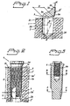
Figure 1 ,reference number 1 designates jaw-bone. A circular hole 2 has been made in the jaw-bone. The hole can be made in a manner known per se using equipment known per se. An implant with threads of different conicities can be applied to the hole. Parts of the said implant are represented by parts of thefree end 3 of the implant. The said free end has atip part 3a which merges into apart 3b. The latter part has athread 3d which has a slight conicity. Slight conicity is understood here as meaning conicities in which an angle of inclination α is of the order of 1° in relation to a vertical axis 2a of the hole 2 or an axis parallel to this axis. Thetip 3a is provided with athread 3e which is arranged with a conicity which gives an angle β of the order of 10°. The entry surface or entry part of thetip 3a has a diameter D' which essentially corresponds to the diameter d of the hole or slightly exceeds the said diameter d. The hole diameter d can also be chosen as a function of the softness of the bone (quality). The upper and lower parts of the hole are indicated by 2c and 2d. -
Figure 2 shows a structural design of theimplant 3 with associatedthread 3d'. Here, the implant has been screwed fully into the hole 2' in the jaw-bone and, on being screwed in, has created a thread 1a in the wall of the hole in the jaw-bone or theside wall 2b of the hole 2'. At its upper part, the implant has securing members/spacer members 4 for a special tooth replacement, tooth prosthesis, etc. (not shown). The member 4 can be provided with a flange 4a with which it is possible to define the final degree of threading of the implant so that optimum thread is exposed to the jaw-bone. As can be seen fromFigure 2 , the implant is in this case provided with cutting edges 5, of a type known per se, at the saidtip 3a'. Thetip part 3a' has a height h which represents 20 - 30% of the total height H of the threaded part of the implant. By means of the conicity, an improved initial stability is obtained through compression 1a, 1b of the bone. -
Figure 3 shows the implant according toFigure 2 in vertical section. In this figure, a threadedrecess 6 is shown whose internal thread has been labelled 6a. The said spacer arrangement 4 according toFigure 2 can be screwed into the said internal thread in a manner known per se. -
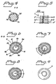
Figure 4 shows that, at the said free end, the implant according toFigures 2 and 3 is designed with cutting edges known per se, which inFigure 4 have been labelled 5a, 5b, 5c and 5d. -
Figure 5 (likeFigure 2 , cf. 1a, 1b) shows that the chosen conicity for thethread 3d' (cf.Figure 1 ) pushes the jaw-bone substance 1" out in radial directions R. The conicity of thethread 3d' and the thread diameter GD of the inclined thread are in this case chosen such that the contact pressure P, P' is of essentially the same order or only slightly increases as the implant 3' is being screwed in adirection 7 into the jaw-bone 1" (the hole made in it). - In accordance with the invention, the
thread 3d/3d' according to the above can be designed with a non-circular/eccentric thread cross-section and/or with a non-circular cross-section for the thread-bearing body.Figures 6, 7 and 8 show different types of non-circularity and positions of rotation of the various thread cross-sections. The individual thread cross-sections can also have different non-circularity. In accordance withFigure 9 , the thread at the tip or free end of the implant can have a circular or concentric thread cross-section which at the top merges into a non-circular thread cross-section according toFigures 6 - 8 . In this way it is possible to achieve a considerable freedom from wobble during tightening. InFigure 6 , one thread is indicated by 8. The thread has a number ofdepressions Figure 6 , cf.Figures 7 and 8. Figure 9 shows the case in which the implant has a circular or concentric thread 9 at the tip. -
Figures 11 and 12 are intended to show so-called multiple thread entries or multiple thread spirals which, depending on the number of entries and spirals, provide different pitches, compare withFigure 10 which shows a design with a single thread entry and thread spiral.Figure 11 shows an embodiment with two thread entries or thread spirals which provide a pitch indicated by Ph', compare with the pitch Ph inFigure 10 . As the principle of double thread spirals is already well known per se, it will not be described in detail here. The principle is already known from completely different areas and for solving completely different problems. In this connection reference may be made to worm gears which use worm screws with multiple thread entries or thread spirals. The principle is also known in a so-called open spiral implant, seeEP-A-263809 Figure 12 shows an embodiment with three thread entries or thread spirals which provide a pitch Ph". The number of thread-entries/thread spirals can be combined with a number of cutting edges (cf.Figure 4, 5a, 5b, 5c, 5d ) so that symmetrical or balanced forces are obtained, i.e. the forces balance each other out. Compare also with the above. - As has been stated above, the insertion time can be shortened in the case of implants which are designed with multiple thread entries. Of course, a shortened fitting time also reduces the expensive operating time, especially when fitting long and numerous implants. For example, when fitting six implants measuring 18 mm in length, which is not unusual in a so-called whole-jaw operation, 5 minutes of operating time are saved if two thread entries are used instead of one. Moreover, if the hole needs to be pre-threaded, then the saving in time is threefold.
-
Figure 13 shows an embodiment of the implant in which the non-circularity of the various thread cross-sections is displaced along the longitudinal direction L of the implant. Eachthread 10 is displaced in relation to theadjacent thread 11 in the direction of rotation. The abovementioned bevelled corners are in this case indicated by 12. The wobble freedom on insertion of the implant into the hole in the bone with an instrument can in this way be further increased, i.e. improved rotational stability is obtained. Fitting is quicker and simpler. In addition, it is possible to use small initially cutting thread cutters to permit maximum thread area in the healing-in process. Some of the abovementioned embodiments can be used as soft-bone fixtures. The invention can also be used in cases where the fitting is to be done with the aid of thread taps (i.e. in two stages). -
Figure 14 shows a complete implant with displaced non-circularity according toFigure 13 and a threadedtip part 13.Figure 15 shows an illustrative embodiment in which the non-circularity between the different thread turns is not displaced. -
Figure 16 shows the relationship for the chosen slight conicity and the hole diameter Hd for ahole 15 drilled in the jaw-bone 14. With the hole diameter Hd = 3 mm, the chosen values a and b for the conicity of thebody 16 can be about 0.55 mm and 0.45 mm, respectively. The constant or essentially constant mutual pressures (cf. P and P') can be achieved in this way. - The conicity can be obtained either by means of the diameter of the whole thread profile gradually increasing as seen from the tip, or by means of the bottom diameter of the thread or its external diameter gradually increasing.
-
Figure 17 shows aconcrete threading bone 19 with the aid of thefixture 20. -
Figure 18 shows the insertion moment as a function of the insertion depth, on the one hand for slightly conical implants and on the other hand for cylindrical implants. Since the pressure does not decrease during the insertion procedure and acts on an increasingly greater area of the implant, this means that the slightly conical implant requires an increasingly greater insertion moment, as can be seen from the figure. The greater insertion moment is a measure of the increased stability of the implant. Cylindrical implants have insertion curves with a constant or even. decreasing moment, especially in the case of poor bone quality, as can also be seen fromFigure 18 . - The invention is not limited to the embodiment shown above by way of example, but can be modified within the scope of the attached patent claims and the inventive concept.
Claims (10)
- Threaded implant (3) for obtaining reliable anchoring in bone substance (1) in the human body, where- the external threading on the implant can cooperate with the side wall (2b) of a hole (2) in the bone substance for reliable anchoring and healing-in of the implant particularly in soft bone substance;- the implant threading has a slight conicity, and the implant threading (3d, 3d', 3e) and the slight conicity extend along most of the length of the implant (3) to force the bone substance out in essentially radial directions (R) as a function of the extent to which the implant is screwed into the hole (2) in the bone,- the conical implant threading (3d, 3d') comprises two or more thread spirals which provide a tight threading on the implant, and- the threaded implant (3) comprises a tip part (3a, 3a') merging into a remaining part (3b),
wherein the implant threading (3d, 3d', 3e) has a stronger conicity at the tip part (3a, 3a') than at the remaining part (3b). - Threaded implant according to claim 1 characterised in that the implant threading (3d, 3d') has a gradually increasing diameter as seen from the tip part (3a) of the implant to ensure that the pressure (P, P') between the bone substance and the implant (3) has essentially a slightly increasing value during the greater part of the operation of screwing the implant into the hole (2) in the bone.
- Threaded implant according to claim 1 characterised in that the conicity of the thread (3d, 3d') at the remaining part (3b) has an angle of inclination (α) of 0.5-2°, and in that the thread conicity of the thread (3e) at said tip part (3a) has an angle of inclination (β) of 10-15°, and in that the tip part (3a, 3a) has a length (h) which is 10 to 30% of the lenght of the total implant threading.
- Threaded implant according to claim 1 characterised in that the implant threading (3d, 3d') along at least part of the longitudinal direction (L) of the implant (3) is given a noncircular or eccentric configuration (8a-8i) for the purpose of obtaining improved rotational stability of the implant in a recently inserted state or an incorporated state of the implant in soft or weak bone substance.
- Threaded implant according to claim 4 characterised in that the tip part (3a) of the implant (3) has a circular or concentric thread (3e) which merges gradually into a non-circular or eccentric thread on the remaining part (3b) of the implant (3).
- Threaded implant according to claim 4 characterised in that the peripheries of the different non-circular or eccentric thread cross-sections have bevelled corners (12) in order to avoid sharp corners.
- Threaded implant according to claim 4 characterised in that the non-circularity is arranged such that areas of maximum diameter are displaced in the peripheral direction from one thread turn (10) to the next thread turn (11).
- Threaded implant according to claim 1 characterised in that the number of thread entries is two, three or four.
- Threaded implant according to claim 8 characterised in that the number of thread entries is adapted to the number of cutting edges (5a, 5b, 5c, 5d) so that symmetrical cutting forces are obtained.
- Threaded implant according to claim 9 characterised in that two thread entries are arranged on the implant together with two or four cutting edges, or in that three threaded entries are arranged together with three cutting edges.
Priority Applications (1)
| Application Number | Priority Date | Filing Date | Title |
|---|---|---|---|
| DE69833559.7T DE69833559T3 (en) | 1997-11-11 | 1998-11-03 | Threaded implant which provides a secure anchoring in the bone |
Applications Claiming Priority (3)
| Application Number | Priority Date | Filing Date | Title |
|---|---|---|---|
| SE9704112A SE516917C2 (en) | 1997-11-11 | 1997-11-11 | Device for providing reliable anchoring of threaded implants in bone |
| SE9704112 | 1997-11-11 | ||
| PCT/SE1998/001982 WO1999023971A1 (en) | 1997-11-11 | 1998-11-03 | Arrangement for obtaining reliable anchoring of a threaded implant in bone |
Publications (3)
| Publication Number | Publication Date |
|---|---|
| EP1030622A1 EP1030622A1 (en) | 2000-08-30 |
| EP1030622B1 EP1030622B1 (en) | 2006-02-22 |
| EP1030622B2 true EP1030622B2 (en) | 2014-05-14 |
Family
ID=20408927
Family Applications (1)
| Application Number | Title | Priority Date | Filing Date |
|---|---|---|---|
| EP98951904.6A Expired - Lifetime EP1030622B2 (en) | 1997-11-11 | 1998-11-03 | Threaded implant for obtaining reliable anchoring in bone |
Country Status (16)
| Country | Link |
|---|---|
| US (2) | US8915735B1 (en) |
| EP (1) | EP1030622B2 (en) |
| JP (1) | JP4039805B2 (en) |
| AT (1) | ATE318119T1 (en) |
| AU (1) | AU745604B2 (en) |
| BR (1) | BR9814634A (en) |
| CA (1) | CA2307304C (en) |
| DE (1) | DE69833559T3 (en) |
| DK (1) | DK1030622T3 (en) |
| ES (1) | ES2256965T5 (en) |
| IL (2) | IL136020A0 (en) |
| NO (1) | NO20002426L (en) |
| PL (1) | PL189970B1 (en) |
| SE (1) | SE516917C2 (en) |
| WO (1) | WO1999023971A1 (en) |
| ZA (1) | ZA9810263B (en) |
Cited By (1)
| Publication number | Priority date | Publication date | Assignee | Title |
|---|---|---|---|---|
| US10149740B2 (en) | 2008-07-24 | 2018-12-11 | Zeev Implants Ltd. | Method and system for dental implantation |
Families Citing this family (23)
| Publication number | Priority date | Publication date | Assignee | Title |
|---|---|---|---|---|
| SE9802571D0 (en) | 1998-07-17 | 1998-07-17 | Astra Ab | Implant |
| SE520756C2 (en) | 2001-12-21 | 2003-08-19 | Nobel Biocare Ab | Method of providing surface structure on implants as well as such implants |
| SE523395C2 (en) | 2001-12-21 | 2004-04-13 | Nobel Biocare Ab | Implants and methods and systems for providing such implants |
| SE526745C2 (en) | 2003-04-17 | 2005-11-01 | Nobel Biocare Ab | Fixture for anchoring in the jawbone |
| IL156033A0 (en) | 2003-05-21 | 2004-03-28 | Ophir Fromovich Ophir Fromovic | Dental implant |
| US8038442B2 (en) | 2007-04-23 | 2011-10-18 | Nobel Biocare Services Ag | Dental implant and dental component connection |
| JP2008307186A (en) * | 2007-06-13 | 2008-12-25 | Univ Kurume | Jaw bone implantation material used for regenerating jaw bone, and method of manufacturing the same |
| WO2009015103A1 (en) | 2007-07-20 | 2009-01-29 | Cochlear Americas | Coupling apparatus for a bone anchored hearing device |
| WO2014083614A1 (en) * | 2012-11-27 | 2014-06-05 | 日東精工株式会社 | Implant screw |
| GB2509135A (en) | 2012-12-21 | 2014-06-25 | Nobel Biocare Services Ag | An abutment with conical metal adapter |
| GB2509138A (en) | 2012-12-21 | 2014-06-25 | Nobel Biocare Services Ag | Dental component with screw fixation |
| GB2509136A (en) | 2012-12-21 | 2014-06-25 | Nobel Biocare Services Ag | Dental component with metal adapter |
| ES2828668T3 (en) * | 2013-03-19 | 2021-05-27 | Medimaps Group Sa | Computer-implemented method to determine an indicator of the stability of a bone implant |
| US11240613B2 (en) * | 2014-01-30 | 2022-02-01 | Cochlear Limited | Bone conduction implant |
| GB2523827A (en) | 2014-03-07 | 2015-09-09 | Nobel Biocare Services Ag | Dental implant |
| GB2523828A (en) | 2014-03-07 | 2015-09-09 | Nobel Biocare Services Ag | Dental implant |
| US10426579B2 (en) | 2014-03-28 | 2019-10-01 | Implant B Ltd. | Renewable dental implant |
| JP6039703B2 (en) * | 2015-01-07 | 2016-12-07 | ハードロック工業株式会社 | Dental implant and its bolt fastening structure |
| KR20180107170A (en) * | 2016-01-29 | 2018-10-01 | 노벨 바이오케어 서비시스 아게 | Dental implants, insertion tools for dental implants, and combinations of dental implants and insertion tools |
| US11376050B2 (en) | 2017-06-27 | 2022-07-05 | Medos International Sarl | Bone screw |
| US10772667B2 (en) | 2017-12-22 | 2020-09-15 | Medos International Sarl | Bone screw with cutting tip |
| US11786343B2 (en) | 2020-07-09 | 2023-10-17 | Southern Implants (Pty) Ltd | Dental implants with stepped threads and systems and methods for making the same |
| WO2024062059A1 (en) | 2022-09-22 | 2024-03-28 | Institut Straumann Ag | Dental implant |
Citations (10)
| Publication number | Priority date | Publication date | Assignee | Title |
|---|---|---|---|---|
| US296362A (en) † | 1884-04-08 | Device for lowering or raising coffins | ||
| WO1983002555A1 (en) † | 1982-01-21 | 1983-08-04 | Us Medical Corp | Prosthesis fixation to bone |
| US4863383A (en) † | 1987-03-17 | 1989-09-05 | Grafelmann Hans L | self-taping screw-in bone implant for dental purposes |
| EP0424734A1 (en) † | 1989-10-26 | 1991-05-02 | Giuseppe Vrespa | Screw device for fixing prostheses to bones |
| US5064425A (en) † | 1986-02-12 | 1991-11-12 | The Institute For Applied Biotechnology | Anchoring member for anchorage in bone tissue |
| DE4142584A1 (en) † | 1991-12-21 | 1993-06-24 | Lang Manfred | Dental implant for retaining false tooth - has sickle shaped ribs with sharp edges arranged in helix |
| WO1994007428A1 (en) † | 1992-10-05 | 1994-04-14 | Astra Aktiebolag | Fixture provided with micro-threads |
| EP0641549A2 (en) † | 1993-08-05 | 1995-03-08 | Zest Anchors, Inc. | Dental implant system |
| US5427527A (en) † | 1993-05-25 | 1995-06-27 | Vent Plant Corporation | Dental implant method of installation |
| US5620323A (en) † | 1994-08-22 | 1997-04-15 | Bressman; Robert A. | Dental restoration structure |
Family Cites Families (12)
| Publication number | Priority date | Publication date | Assignee | Title |
|---|---|---|---|---|
| US4414966A (en) * | 1981-04-09 | 1983-11-15 | Ace Orthopedic Manufacturing, Inc. | Fixation pin |
| US4624673A (en) | 1982-01-21 | 1986-11-25 | United States Medical Corporation | Device system for dental prosthesis fixation to bone |
| USD296362S (en) | 1985-02-15 | 1988-06-21 | The Institute For Applied Biotechnology | Dental implant |
| CA1248371A (en) | 1985-05-17 | 1989-01-10 | Robin D. Listrom | Fixture for attaching prosthesis to bone |
| AT385409B (en) * | 1986-09-22 | 1988-03-25 | Putz Erich Dr Med | DENTAL IMPLANT |
| SE468154B (en) * | 1991-08-27 | 1992-11-16 | Nobelpharma Ab | SCREW SIZE TITAN MOUNTING FOR PERMANENT ANCHORING IN BONE TISSUE. |
| IT1253481B (en) * | 1991-10-08 | 1995-08-08 | SCREW ENDOSSEO DENTAL IMPLANT. | |
| US5246370A (en) | 1992-11-27 | 1993-09-21 | Coatoam Gary W | Dental implant method |
| US5269686A (en) * | 1993-05-10 | 1993-12-14 | James Robert A | Threaded drivable dental implant |
| US5527183A (en) * | 1993-08-18 | 1996-06-18 | Collaborative Enterprises, Inc. | Endosseous implant system |
| WO1997025933A1 (en) * | 1996-01-18 | 1997-07-24 | Implant Innovations, Inc. | Reduced friction screw-type dental implant |
| KR200207524Y1 (en) | 2000-07-12 | 2000-12-15 | 박영철 | Orthodontic implant |
-
1997
- 1997-11-11 SE SE9704112A patent/SE516917C2/en not_active IP Right Cessation
-
1998
- 1998-11-03 DK DK98951904T patent/DK1030622T3/en active
- 1998-11-03 WO PCT/SE1998/001982 patent/WO1999023971A1/en active Search and Examination
- 1998-11-03 IL IL13602098A patent/IL136020A0/en active IP Right Grant
- 1998-11-03 CA CA002307304A patent/CA2307304C/en not_active Expired - Fee Related
- 1998-11-03 PL PL98340369A patent/PL189970B1/en unknown
- 1998-11-03 BR BR9814634-3A patent/BR9814634A/en not_active IP Right Cessation
- 1998-11-03 JP JP2000520072A patent/JP4039805B2/en not_active Expired - Lifetime
- 1998-11-03 EP EP98951904.6A patent/EP1030622B2/en not_active Expired - Lifetime
- 1998-11-03 DE DE69833559.7T patent/DE69833559T3/en not_active Expired - Lifetime
- 1998-11-03 AT AT98951904T patent/ATE318119T1/en active
- 1998-11-03 ES ES98951904.6T patent/ES2256965T5/en not_active Expired - Lifetime
- 1998-11-03 AU AU97737/98A patent/AU745604B2/en not_active Expired
- 1998-11-03 US US09/509,869 patent/US8915735B1/en not_active Expired - Fee Related
- 1998-11-10 ZA ZA9810263A patent/ZA9810263B/en unknown
-
2000
- 2000-05-08 IL IL136020A patent/IL136020A/en not_active IP Right Cessation
- 2000-05-10 NO NO20002426A patent/NO20002426L/en not_active Application Discontinuation
-
2014
- 2014-10-27 US US14/524,742 patent/US9375295B2/en not_active Expired - Fee Related
Patent Citations (10)
| Publication number | Priority date | Publication date | Assignee | Title |
|---|---|---|---|---|
| US296362A (en) † | 1884-04-08 | Device for lowering or raising coffins | ||
| WO1983002555A1 (en) † | 1982-01-21 | 1983-08-04 | Us Medical Corp | Prosthesis fixation to bone |
| US5064425A (en) † | 1986-02-12 | 1991-11-12 | The Institute For Applied Biotechnology | Anchoring member for anchorage in bone tissue |
| US4863383A (en) † | 1987-03-17 | 1989-09-05 | Grafelmann Hans L | self-taping screw-in bone implant for dental purposes |
| EP0424734A1 (en) † | 1989-10-26 | 1991-05-02 | Giuseppe Vrespa | Screw device for fixing prostheses to bones |
| DE4142584A1 (en) † | 1991-12-21 | 1993-06-24 | Lang Manfred | Dental implant for retaining false tooth - has sickle shaped ribs with sharp edges arranged in helix |
| WO1994007428A1 (en) † | 1992-10-05 | 1994-04-14 | Astra Aktiebolag | Fixture provided with micro-threads |
| US5427527A (en) † | 1993-05-25 | 1995-06-27 | Vent Plant Corporation | Dental implant method of installation |
| EP0641549A2 (en) † | 1993-08-05 | 1995-03-08 | Zest Anchors, Inc. | Dental implant system |
| US5620323A (en) † | 1994-08-22 | 1997-04-15 | Bressman; Robert A. | Dental restoration structure |
Non-Patent Citations (3)
| Title |
|---|
| "Implant Placement Procedure", NOBEL BIOCARE AB, GÕTEBORG, pages: 39 - 40 † |
| "Van Nostrand's Scientific Encyclopedia", vol. 3, January 1958, D. VAN NOSTRAND COMPANY, INC., NEW JERSEY, pages: 1468 † |
| BRÅNEMARK SYSTEM: "The Treatment of the Edentulous Jaw", RESTORATIVE DENTIST'S MANUAL, 10 November 2008 (2008-11-10), pages A-2 - A-3 † |
Cited By (1)
| Publication number | Priority date | Publication date | Assignee | Title |
|---|---|---|---|---|
| US10149740B2 (en) | 2008-07-24 | 2018-12-11 | Zeev Implants Ltd. | Method and system for dental implantation |
Also Published As
| Publication number | Publication date |
|---|---|
| CA2307304C (en) | 2009-02-17 |
| ZA9810263B (en) | 1999-05-26 |
| JP2001522637A (en) | 2001-11-20 |
| WO1999023971A1 (en) | 1999-05-20 |
| BR9814634A (en) | 2000-10-03 |
| DE69833559T3 (en) | 2014-10-09 |
| ES2256965T3 (en) | 2006-07-16 |
| CA2307304A1 (en) | 1999-05-20 |
| IL136020A (en) | 2006-06-11 |
| AU745604B2 (en) | 2002-03-21 |
| ES2256965T5 (en) | 2014-06-04 |
| NO20002426L (en) | 2000-07-10 |
| JP4039805B2 (en) | 2008-01-30 |
| SE9704112L (en) | 1999-05-12 |
| SE9704112D0 (en) | 1997-11-11 |
| US20150044639A1 (en) | 2015-02-12 |
| US8915735B1 (en) | 2014-12-23 |
| PL340369A1 (en) | 2001-01-29 |
| SE516917C2 (en) | 2002-03-19 |
| WO1999023971A9 (en) | 2000-07-20 |
| DK1030622T3 (en) | 2006-06-26 |
| EP1030622B1 (en) | 2006-02-22 |
| EP1030622A1 (en) | 2000-08-30 |
| AU9773798A (en) | 1999-05-31 |
| DE69833559T2 (en) | 2006-12-21 |
| US9375295B2 (en) | 2016-06-28 |
| DE69833559D1 (en) | 2006-04-27 |
| NO20002426D0 (en) | 2000-05-10 |
| PL189970B1 (en) | 2005-10-31 |
| IL136020A0 (en) | 2001-05-20 |
| ATE318119T1 (en) | 2006-03-15 |
Similar Documents
| Publication | Publication Date | Title |
|---|---|---|
| US9375295B2 (en) | Arrangement for obtaining reliable anchoring of a threaded implant in a bone | |
| EP1098605B2 (en) | Dental implant | |
| JP4278305B2 (en) | Implant | |
| US6726480B1 (en) | Support for sustaining and/or forming a dental prosthesis | |
| JP3064032B2 (en) | Dental implant | |
| EP2328509B1 (en) | Compact dental implant | |
| EP3539504B1 (en) | Condensing skeletal implant that facilitates insertion | |
| US20140199658A1 (en) | Dental implant with multiple thread patterns | |
| EP1030623A1 (en) | Arrangement and its use for anchoring a threaded implant in bone, for example dentine | |
| CA2109850C (en) | Anchoring element for anchorage in bone tissue | |
| US20110081626A1 (en) | Dental implant | |
| RU2637612C2 (en) | Dental implant kit | |
| JP4276538B2 (en) | Implant | |
| KR20210072068A (en) | dental implant thread | |
| CN111107808B (en) | Dental implant | |
| AU2002341118A1 (en) | Implant | |
| AU679019B2 (en) | Anchoring element for anchorage in bone tissue |
Legal Events
| Date | Code | Title | Description |
|---|---|---|---|
| PUAI | Public reference made under article 153(3) epc to a published international application that has entered the european phase |
Free format text: ORIGINAL CODE: 0009012 |
|
| 17P | Request for examination filed |
Effective date: 20000613 |
|
| AK | Designated contracting states |
Kind code of ref document: A1 Designated state(s): AT BE CH DE DK ES FR GB GR IT LI NL SE |
|
| 17Q | First examination report despatched |
Effective date: 20040702 |
|
| GRAP | Despatch of communication of intention to grant a patent |
Free format text: ORIGINAL CODE: EPIDOSNIGR1 |
|
| RTI1 | Title (correction) |
Free format text: THREADED IMPLANT FOR OBTAINING RELIABLE ANCHORING IN BONE |
|
| GRAS | Grant fee paid |
Free format text: ORIGINAL CODE: EPIDOSNIGR3 |
|
| GRAA | (expected) grant |
Free format text: ORIGINAL CODE: 0009210 |
|
| AK | Designated contracting states |
Kind code of ref document: B1 Designated state(s): AT BE CH DE DK ES FR GB GR IT LI NL SE |
|
| PG25 | Lapsed in a contracting state [announced via postgrant information from national office to epo] |
Ref country code: IT Free format text: LAPSE BECAUSE OF FAILURE TO SUBMIT A TRANSLATION OF THE DESCRIPTION OR TO PAY THE FEE WITHIN THE PRESCRIBED TIME-LIMIT;WARNING: LAPSES OF ITALIAN PATENTS WITH EFFECTIVE DATE BEFORE 2007 MAY HAVE OCCURRED AT ANY TIME BEFORE 2007. THE CORRECT EFFECTIVE DATE MAY BE DIFFERENT FROM THE ONE RECORDED. Effective date: 20060222 |
|
| REG | Reference to a national code |
Ref country code: GB Ref legal event code: FG4D |
|
| REG | Reference to a national code |
Ref country code: CH Ref legal event code: EP |
|
| REG | Reference to a national code |
Ref country code: CH Ref legal event code: NV Representative=s name: E. BLUM & CO. PATENTANWAELTE |
|
| REF | Corresponds to: |
Ref document number: 69833559 Country of ref document: DE Date of ref document: 20060427 Kind code of ref document: P |
|
| REG | Reference to a national code |
Ref country code: SE Ref legal event code: TRGR |
|
| REG | Reference to a national code |
Ref country code: DK Ref legal event code: T3 |
|
| REG | Reference to a national code |
Ref country code: GR Ref legal event code: EP Ref document number: 20060401527 Country of ref document: GR |
|
| REG | Reference to a national code |
Ref country code: ES Ref legal event code: FG2A Ref document number: 2256965 Country of ref document: ES Kind code of ref document: T3 |
|
| ET | Fr: translation filed | ||
| PLBI | Opposition filed |
Free format text: ORIGINAL CODE: 0009260 |
|
| 26 | Opposition filed |
Opponent name: NEOSS LIMITED Effective date: 20061122 Opponent name: ASTRA TECH AB Effective date: 20061121 |
|
| PLAX | Notice of opposition and request to file observation + time limit sent |
Free format text: ORIGINAL CODE: EPIDOSNOBS2 |
|
| NLR1 | Nl: opposition has been filed with the epo |
Opponent name: NEOSS LIMITED Opponent name: ASTRA TECH AB |
|
| PLAF | Information modified related to communication of a notice of opposition and request to file observations + time limit |
Free format text: ORIGINAL CODE: EPIDOSCOBS2 |
|
| PLBB | Reply of patent proprietor to notice(s) of opposition received |
Free format text: ORIGINAL CODE: EPIDOSNOBS3 |
|
| REG | Reference to a national code |
Ref country code: CH Ref legal event code: PFA Owner name: NOBEL BIOCARE AB (PUBL) Free format text: NOBEL BIOCARE AB (PUBL)#BOX 5190#402 26 GOETEBORG (SE) -TRANSFER TO- NOBEL BIOCARE AB (PUBL)#BOX 5190#402 26 GOETEBORG (SE) |
|
| APBM | Appeal reference recorded |
Free format text: ORIGINAL CODE: EPIDOSNREFNO |
|
| APBP | Date of receipt of notice of appeal recorded |
Free format text: ORIGINAL CODE: EPIDOSNNOA2O |
|
| APAH | Appeal reference modified |
Free format text: ORIGINAL CODE: EPIDOSCREFNO |
|
| APAW | Appeal reference deleted |
Free format text: ORIGINAL CODE: EPIDOSDREFNO |
|
| APBM | Appeal reference recorded |
Free format text: ORIGINAL CODE: EPIDOSNREFNO |
|
| APBP | Date of receipt of notice of appeal recorded |
Free format text: ORIGINAL CODE: EPIDOSNNOA2O |
|
| APBQ | Date of receipt of statement of grounds of appeal recorded |
Free format text: ORIGINAL CODE: EPIDOSNNOA3O |
|
| APBQ | Date of receipt of statement of grounds of appeal recorded |
Free format text: ORIGINAL CODE: EPIDOSNNOA3O |
|
| RAP2 | Party data changed (patent owner data changed or rights of a patent transferred) |
Owner name: NOBEL BIOCARE SERVICES AG |
|
| PGFP | Annual fee paid to national office [announced via postgrant information from national office to epo] |
Ref country code: AT Payment date: 20100927 Year of fee payment: 13 |
|
| PG25 | Lapsed in a contracting state [announced via postgrant information from national office to epo] |
Ref country code: IT Free format text: LAPSE BECAUSE OF NON-PAYMENT OF DUE FEES Effective date: 20091103 |
|
| PGFP | Annual fee paid to national office [announced via postgrant information from national office to epo] |
Ref country code: GR Payment date: 20101130 Year of fee payment: 13 |
|
| PGRI | Patent reinstated in contracting state [announced from national office to epo] |
Ref country code: IT Effective date: 20110616 |
|
| PLAB | Opposition data, opponent's data or that of the opponent's representative modified |
Free format text: ORIGINAL CODE: 0009299OPPO |
|
| REG | Reference to a national code |
Ref country code: CH Ref legal event code: PUE Owner name: NOBEL BIOCARE SERVICES AG Free format text: NOBEL BIOCARE AB (PUBL)#BOX 5190#402 26 GOETEBORG (SE) -TRANSFER TO- NOBEL BIOCARE SERVICES AG#POSTFACH#8058 ZUERICH-FLUGHAFEN (CH) |
|
| R26 | Opposition filed (corrected) |
Opponent name: NEOSS LIMITED Effective date: 20061122 Opponent name: ASTRA TECH AB Effective date: 20061121 |
|
| REG | Reference to a national code |
Ref country code: NL Ref legal event code: SD Effective date: 20110902 |
|
| PGFP | Annual fee paid to national office [announced via postgrant information from national office to epo] |
Ref country code: DK Payment date: 20110926 Year of fee payment: 14 |
|
| PGFP | Annual fee paid to national office [announced via postgrant information from national office to epo] |
Ref country code: NL Payment date: 20110927 Year of fee payment: 14 |
|
| PGFP | Annual fee paid to national office [announced via postgrant information from national office to epo] |
Ref country code: BE Payment date: 20110922 Year of fee payment: 14 |
|
| REG | Reference to a national code |
Ref country code: DE Ref legal event code: R082 Ref document number: 69833559 Country of ref document: DE Representative=s name: GLAWE, DELFS, MOLL, PATENTANWAELTE, DE |
|
| REG | Reference to a national code |
Ref country code: DE Ref legal event code: R082 Ref document number: 69833559 Country of ref document: DE Representative=s name: HOFFMANN - EITLE PATENT- UND RECHTSANWAELTE PA, DE Effective date: 20120227 Ref country code: DE Ref legal event code: R082 Ref document number: 69833559 Country of ref document: DE Representative=s name: HOFFMANN - EITLE, DE Effective date: 20120227 Ref country code: DE Ref legal event code: R081 Ref document number: 69833559 Country of ref document: DE Owner name: NOBEL BIOCARE SERVICES AG, CH Free format text: FORMER OWNER: NOBEL BIOCARE AB (PUBL), GOETEBURG/GOETEBORG, SE Effective date: 20120227 |
|
| REG | Reference to a national code |
Ref country code: GB Ref legal event code: 732E Free format text: REGISTERED BETWEEN 20120419 AND 20120425 |
|
| BERE | Be: lapsed |
Owner name: NOBEL BIOCARE SERVICE A.G. Effective date: 20121130 |
|
| REG | Reference to a national code |
Ref country code: NL Ref legal event code: V1 Effective date: 20130601 |
|
| REG | Reference to a national code |
Ref country code: DK Ref legal event code: EBP |
|
| REG | Reference to a national code |
Ref country code: AT Ref legal event code: MM01 Ref document number: 318119 Country of ref document: AT Kind code of ref document: T Effective date: 20121103 |
|
| PG25 | Lapsed in a contracting state [announced via postgrant information from national office to epo] |
Ref country code: AT Free format text: LAPSE BECAUSE OF NON-PAYMENT OF DUE FEES Effective date: 20121103 |
|
| PG25 | Lapsed in a contracting state [announced via postgrant information from national office to epo] |
Ref country code: NL Free format text: LAPSE BECAUSE OF NON-PAYMENT OF DUE FEES Effective date: 20130601 Ref country code: BE Free format text: LAPSE BECAUSE OF NON-PAYMENT OF DUE FEES Effective date: 20121130 |
|
| REG | Reference to a national code |
Ref country code: GR Ref legal event code: ML Ref document number: 20060401527 Country of ref document: GR Effective date: 20130604 |
|
| APBU | Appeal procedure closed |
Free format text: ORIGINAL CODE: EPIDOSNNOA9O |
|
| PG25 | Lapsed in a contracting state [announced via postgrant information from national office to epo] |
Ref country code: DK Free format text: LAPSE BECAUSE OF NON-PAYMENT OF DUE FEES Effective date: 20121130 |
|
| REG | Reference to a national code |
Ref country code: DE Ref legal event code: R008 Ref document number: 69833559 Country of ref document: DE |
|
| REG | Reference to a national code |
Ref country code: DE Ref legal event code: R082 Ref document number: 69833559 Country of ref document: DE Representative=s name: HOFFMANN - EITLE PATENT- UND RECHTSANWAELTE PA, DE Ref country code: DE Ref legal event code: R082 Ref document number: 69833559 Country of ref document: DE Representative=s name: HOFFMANN - EITLE, DE |
|
| PUAH | Patent maintained in amended form |
Free format text: ORIGINAL CODE: 0009272 |
|
| STAA | Information on the status of an ep patent application or granted ep patent |
Free format text: STATUS: PATENT MAINTAINED AS AMENDED |
|
| 27A | Patent maintained in amended form |
Effective date: 20140514 |
|
| AK | Designated contracting states |
Kind code of ref document: B2 Designated state(s): AT BE CH DE DK ES FR GB GR IT LI NL SE |
|
| REG | Reference to a national code |
Ref country code: DE Ref legal event code: R102 Ref document number: 69833559 Country of ref document: DE |
|
| REG | Reference to a national code |
Ref country code: CH Ref legal event code: AELC |
|
| REG | Reference to a national code |
Ref country code: ES Ref legal event code: DC2A Ref document number: 2256965 Country of ref document: ES Kind code of ref document: T5 Effective date: 20140604 |
|
| REG | Reference to a national code |
Ref country code: DE Ref legal event code: R102 Ref document number: 69833559 Country of ref document: DE Effective date: 20140514 |
|
| REG | Reference to a national code |
Ref country code: DE Ref legal event code: R039 Ref document number: 69833559 Country of ref document: DE Effective date: 20140328 |
|
| REG | Reference to a national code |
Ref country code: SE Ref legal event code: RPEO |
|
| PG25 | Lapsed in a contracting state [announced via postgrant information from national office to epo] |
Ref country code: GR Free format text: LAPSE BECAUSE OF FAILURE TO SUBMIT A TRANSLATION OF THE DESCRIPTION OR TO PAY THE FEE WITHIN THE PRESCRIBED TIME-LIMIT Effective date: 20140815 |
|
| PG25 | Lapsed in a contracting state [announced via postgrant information from national office to epo] |
Ref country code: GR Free format text: LAPSE BECAUSE OF FAILURE TO SUBMIT A TRANSLATION OF THE DESCRIPTION OR TO PAY THE FEE WITHIN THE PRESCRIBED TIME-LIMIT Effective date: 20130604 |
|
| REG | Reference to a national code |
Ref country code: FR Ref legal event code: PLFP Year of fee payment: 18 |
|
| REG | Reference to a national code |
Ref country code: DE Ref legal event code: R097 Ref document number: 69833559 Country of ref document: DE Ref country code: DE Ref legal event code: R040 Ref document number: 69833559 Country of ref document: DE |
|
| REG | Reference to a national code |
Ref country code: FR Ref legal event code: PLFP Year of fee payment: 19 |
|
| REG | Reference to a national code |
Ref country code: FR Ref legal event code: PLFP Year of fee payment: 20 |
|
| PGFP | Annual fee paid to national office [announced via postgrant information from national office to epo] |
Ref country code: IT Payment date: 20170918 Year of fee payment: 20 |
|
| PGFP | Annual fee paid to national office [announced via postgrant information from national office to epo] |
Ref country code: SE Payment date: 20170919 Year of fee payment: 20 |
|
| PGFP | Annual fee paid to national office [announced via postgrant information from national office to epo] |
Ref country code: FR Payment date: 20171003 Year of fee payment: 20 Ref country code: DE Payment date: 20170919 Year of fee payment: 20 |
|
| PGFP | Annual fee paid to national office [announced via postgrant information from national office to epo] |
Ref country code: CH Payment date: 20171024 Year of fee payment: 20 Ref country code: ES Payment date: 20171201 Year of fee payment: 20 Ref country code: GB Payment date: 20171121 Year of fee payment: 20 |
|
| REG | Reference to a national code |
Ref country code: DE Ref legal event code: R071 Ref document number: 69833559 Country of ref document: DE |
|
| REG | Reference to a national code |
Ref country code: CH Ref legal event code: PL |
|
| REG | Reference to a national code |
Ref country code: GB Ref legal event code: PE20 Expiry date: 20181102 |
|
| REG | Reference to a national code |
Ref country code: SE Ref legal event code: EUG |
|
| PG25 | Lapsed in a contracting state [announced via postgrant information from national office to epo] |
Ref country code: GB Free format text: LAPSE BECAUSE OF EXPIRATION OF PROTECTION Effective date: 20181102 |
|
| REG | Reference to a national code |
Ref country code: ES Ref legal event code: FD2A Effective date: 20220128 |
|
| PG25 | Lapsed in a contracting state [announced via postgrant information from national office to epo] |
Ref country code: ES Free format text: LAPSE BECAUSE OF EXPIRATION OF PROTECTION Effective date: 20181104 |