EP1030344A2 - Continuously variable aperture for high-energy ion implanter - Google Patents
Continuously variable aperture for high-energy ion implanter Download PDFInfo
- Publication number
- EP1030344A2 EP1030344A2 EP00301220A EP00301220A EP1030344A2 EP 1030344 A2 EP1030344 A2 EP 1030344A2 EP 00301220 A EP00301220 A EP 00301220A EP 00301220 A EP00301220 A EP 00301220A EP 1030344 A2 EP1030344 A2 EP 1030344A2
- Authority
- EP
- European Patent Office
- Prior art keywords
- aperture
- control
- ion beam
- control arms
- drive mechanism
- Prior art date
- Legal status (The legal status is an assumption and is not a legal conclusion. Google has not performed a legal analysis and makes no representation as to the accuracy of the status listed.)
- Granted
Links
Images




Classifications
-
- H—ELECTRICITY
- H01—ELECTRIC ELEMENTS
- H01J—ELECTRIC DISCHARGE TUBES OR DISCHARGE LAMPS
- H01J37/00—Discharge tubes with provision for introducing objects or material to be exposed to the discharge, e.g. for the purpose of examination or processing thereof
- H01J37/30—Electron-beam or ion-beam tubes for localised treatment of objects
- H01J37/317—Electron-beam or ion-beam tubes for localised treatment of objects for changing properties of the objects or for applying thin layers thereon, e.g. for ion implantation
- H01J37/3171—Electron-beam or ion-beam tubes for localised treatment of objects for changing properties of the objects or for applying thin layers thereon, e.g. for ion implantation for ion implantation
-
- H—ELECTRICITY
- H10—SEMICONDUCTOR DEVICES; ELECTRIC SOLID-STATE DEVICES NOT OTHERWISE PROVIDED FOR
- H10P—GENERIC PROCESSES OR APPARATUS FOR THE MANUFACTURE OR TREATMENT OF DEVICES COVERED BY CLASS H10
- H10P30/00—Ion implantation into wafers, substrates or parts of devices
- H10P30/20—Ion implantation into wafers, substrates or parts of devices into semiconductor materials, e.g. for doping
-
- H—ELECTRICITY
- H01—ELECTRIC ELEMENTS
- H01J—ELECTRIC DISCHARGE TUBES OR DISCHARGE LAMPS
- H01J37/00—Discharge tubes with provision for introducing objects or material to be exposed to the discharge, e.g. for the purpose of examination or processing thereof
- H01J37/02—Details
- H01J37/04—Arrangements of electrodes and associated parts for generating or controlling the discharge, e.g. electron-optical arrangement or ion-optical arrangement
- H01J37/09—Diaphragms; Shields associated with electron or ion-optical arrangements; Compensation of disturbing fields
-
- H—ELECTRICITY
- H01—ELECTRIC ELEMENTS
- H01J—ELECTRIC DISCHARGE TUBES OR DISCHARGE LAMPS
- H01J2237/00—Discharge tubes exposing object to beam, e.g. for analysis treatment, etching, imaging
- H01J2237/30—Electron or ion beam tubes for processing objects
- H01J2237/304—Controlling tubes
Definitions
- the present invention relates generally to high-energy ion implantation systems and more particularly to a continuously variable aperture for use in such systems.
- High-energy ion implanters are used for deep implants into a substrate. Such deep implants are required to create, for example, retrograde wells. Eaton GSD/HE and GSD/VHE ion implanters are examples of such high-energy implanters. These implanters can provide ion beams at energy levels up to 5 MeV (million electron volts).
- U.S. Patent No. 4,667,111 assigned to the assignee of the present invention, Eaton Corporation, and describing such a high-energy ion implanter, is incorporated by reference herein as if fully set forth.
- implants are performed on semiconductor substrates in prescribed series of processes or recipes.
- Each series may include several recipes, each of which requires a particular level of ion beam current.
- Current methods of adjusting the ion beam current for different recipes involves an initial tuning of the ion beam source for a particular level of beam current, and then re-tuning the source for any subsequent different level of beam current.
- Such a method can be time consuming and is most detrimental when beam recipes involving a common species (e . g ., boron or phosphorous) are connected in a series chain.
- the time saved by running recipes in series is offset by the time required to re-tune the source between recipes.
- a variable aperture assembly is provided for controlling the amount of ion beam current passing therethrough in an ion implantation system.
- the aperture assembly comprises an aperture defined by opposing first and second aperture plates through which an ion beam passes; control arms connected, respectively, to the first and second aperture plates; and an aperture drive mechanism for simultaneously imparting movement to the control arms in opposite directions to adjust a gap between the aperture plates to thereby control the amount of current passing through the aperture.
- Each of the opposite directions in which the control arms move is generally perpendicular to an axis along which the ion beam passes.
- a control system is also provided for automatically adjusting the aperture gap based on inputs representing actual ion beam current passing through the implanter beamline, desired ion beam current, and aperture position.
- the control system includes control logic for receiving the inputs and outputting control signals to the aperture drive mechanism to adjust the aperture gap.
- FIG. 1 A cross sectional plan view of a high-energy ion implanter 10 is shown in Figure 1.
- the implanter 10 comprises five sections or subsystems: an injector 12 including an ion source 14 for producing an ion beam and a mass analysis magnet 16 for mass analyzing the ion beam; a radio frequency (RF) linear accelerator (linac) 18 including a plurality of resonator modules 20 for accelerating the ion beam to a higher energy; a final energy magnet (FEM) 22 for performing final mass analysis of the accelerated ion beam; a resolver housing 23 for final resolution and conditioning of the ion beam; and an end station 24 which contains a rotating disc 26 carrying wafers W to be implanted by the ion beam.
- RF radio frequency
- linac radio frequency linear accelerator
- FEM final energy magnet
- a continuously variable aperture assembly 30 Positioned after the mass analysis magnet 16 at the entrance of the linac 18 is a continuously variable aperture assembly 30 which functions to control the amount of ion beam current which passes from the mass analysis magnet 16 to the linac 18. Located immediately after the continuously variable aperture 30 is a first flag Faraday 31 which is used to measure the beam current out of the aperture 30 and into the linac.
- the mass analysis magnet 16 functions to pass to the RF linac 18 only the ions generated by the ion source 14 having an appropriate charge-to-mass ratio.
- the mass analysis magnet is required because the ion source 14, in addition to generating ions of appropriate charge-to-mass ratio, also generates ions of greater or lesser charge-to-mass ratio than that desired. Ions having inappropriate charge-to-mass ratios are not suitable for implantation into the wafer.
- the ion beam that passes through the mass analysis magnet 16 is typically comprised of a single isotope and enters the RF linac 18 which imparts additional energy to the ion beam passing therethrough.
- the RF linac produces particle accelerating fields which vary periodically with time, the phase of which may be adjusted to accommodate different atomic number particles as well as particles having different speeds.
- Each of the plurality of resonator modules 20 in the RF linac 18 functions to further accelerate ions beyond the energies they achieve from a previous module.
- the resolver housing 23 resides downstream of the linac 18.
- the housing contains a second flag Faraday 35 for measuring the current of the ion beam prior to implanting into the wafer.
- the continuously variable aperture 30 disposed between the mass analysis magnet 16 and the RF linac 18 is shown in greater detail in Figure 2.
- the aperture 30 comprises an aperture subassembly 32, residing generally interior of a mounting plate 34, and an aperture drive mechanism 36, residing generally exterior of the mounting plate 34.
- the mounting plate 34 defines the interface between the interior of the implanter beamline, which operates under vacuum conditions, and the exterior of the implanter beamline, which resides at an ambient atmospheric pressure.
- the mounting plate is cooled by means of a cooling medium (such as water) which is carried by internal channels via inlet 38 and outlet 40.
- the aperture subassembly 32 comprises a graphite fixed defining aperture 42 behind which resides a graphite variable aperture 44 comprised of aperture plate 44A and 44B.
- the aperture plates 44A and 44B are attached to stainless steel control arms 46A and 46B, respectively, by means of fasteners such as screws 48.
- the gap 50 between the aperture plates 44A and 44B defines a space, having a longitudinal axis 49, through which an ion beam may pass during operation of the ion implanter of Figure 1.
- the aperture drive mechanism 36 moves the control arms 46A and 46B toward and away from each other in a direction parallel to axis 51 to vary the width of the gap 50 between aperture plates 44A and 44B.
- Axis 51 is generally perpendicular to the axis along which the ion beam travels.
- the aperture drive mechanism 36 includes a fixed mounting block 52 that is fixedly spaced from the mounting plate 34 by means of linear shafts or ways 54 and 56.
- the linear ways 54 and 56 are attached to the mounting plate 34 by means of mountings 58 and 60, respectively.
- the linear ways 54 and 56 provide means along which the movable portion of the drive mechanism slides to permit adjustment of the gap 50 between the aperture plates 44A and 44B.
- Control arm 46A (to which aperture plate 44A is attached) is connected to block assembly, 62, 64, 66, which slides bi-directionally along linear way 56.
- the control arm 46A is fixedly attached to block 62; block 62 is fixedly attached to block 64; and block 64 is fixedly attached to block 66. Accordingly, by moving block 66 in a direction parallel to axis 51, movement is imparted to block 64 which slides along linear way 56, thereby imparting corresponding axial movement to block 62 and the control arm 46A.
- the entire block assembly 62, 64, 66 moves in a direction parallel to axis 51.
- An expansible steel bellows 70 is provided at the interface of the control arm 46A and the exterior of the mounting plate 34 to maintain vacuum conditions on the interior side of the mounting plate, while permitting the control arm 46A to move through the mounting plate.
- control arm 46B (to which aperture plate 44B is attached) is connected to block assembly, 72, 74, 76, which slides bi-directionally along linear way 54.
- the control arm 46B is fixedly attached to block 72; block 72 is fixedly attached to block 74; and block 74 is fixedly attached to block 76. Accordingly, by moving block 76 in a direction parallel to axis 51, movement is imparted to block 74 which slides along linear way 54, thereby imparting corresponding axial movement to block 72 and the control arm 46B.
- the entire block assembly 72, 74, 76 moves in a direction parallel to axis 51.
- An expansible steel bellows 80 is provided at the interface of the control arm 46B and the exterior of the mounting plate 34 to maintain vacuum conditions on the interior side of the mounting plate, while permitting the control arm 46B to move through the mounting plate.
- the block assemblies 61, 64, 66 and 72, 74, 76 are moved toward and away from each other in opposite directions parallel to axis 51 by a motorized threaded shaft assembly including a DC motor 82 and a threaded shaft 84.
- the threaded shaft 84 is provided with a first threaded portion 84A having an end that is connected to the mounting block 52 by a bearing mount 86.
- the threaded shaft 84 is provided with a second oppositely threaded portion 84B having an end that is connected to mounting plate 34 by an internal bearing (not shown).
- the threaded shaft 84 is secured at its ends to the mounting block 52 and the mounting plate 34 while being permitted to rotate bi-directionally along axis 51.
- Block 76 is provided with internal treads that match those of the first threaded portion 84A
- block 66 is provided with internal treads that match those of the second oppositely threaded portion 84B.
- DC motor 82 is coupled to the threaded shaft 84 by means of shaft coupling 88. Power is supplied to the motor 82 via leads 90. By applying oppositely biased voltages to the DC motor, the threaded shaft 84 may be rotated in opposite directions. Because the first threaded portion 84A and the second threaded portion 84B are oppositely threaded, rotation of the threaded shaft moves the block assembly 62, 64,66 in one direction parallel to axis 51 and moves the block assembly 72, 74, 76 in an opposite direction parallel to axis 51. The block assemblies are connected to their respective control arms 46A and 46B.
- the width of the aperture gap 50 may be made smaller or larger by moving the aperture plates 44A and 44B toward or away from each other. In this manner, ion beam current passing trough aperture 44 may be adjusted.
- the aperture plates 44A and 44B may either overlap or abut each other in the closed position to insure that no beam current passes therethrough.
- the tilt angle ⁇ defined by the axis 49 of aperture 44 and axis 51 is fixed on the order of 45°.
- FIG. 2 and 3 An alternative to the motorized threaded shaft assembly provided in Figures 2 and 3 is a motorized rack and pinion assembly (not shown).
- the motorized rotary movement of a pinion located between a pair of rack bars may be used to impart opposing movement to the rack bars.
- By connecting each of the rack bars to a respective control arm, rotary movement of the pinion by the motor may be used to adjust the aperture gap.
- control arms 46A and 46B are cooled by a medium such as water.
- Control arm 46A is provided wit a coaxial construction utilizing an inner sheath 92 into which water is injected via inlet 96 and an outer sheath 94 trough which water exits via outlet 98.
- control arm 46B is provided with a coaxial construction utilizing an inner sheath 100 into which water is injected via inlet 104 and an outer sheath 102 trough which water exits via outlet 106.
- the position of the control arms 46A and 46B may be monitored using proximity switches 108 and 110 that are mounted to mounting block 52. Fins 112 and 114, mounted to blocks 72 and 62, respectively, activate switches 108 and 110, respectively, when they are in close proximity thereto. When switch 108 is activated, the aperture 44 is in its most closed position, and when switch 110 is activated, the aperture 44 is in its most open position (roughly .16" (.41 cm) in the preferred embodiment).
- a linear potentiometer comprising a plunger 116 and a receiving portion 118 may be included with the threaded shaft assembly for providing an indication of the distance between block assemblies 62, 64, 66 and 72, 74, 76, thereby providing an indication of the position of the aperture 44 and thus the width of the aperture gap 50.
- a rotary encoder may be coupled to the DC motor shaft or the threaded shaft 84 to provide such position information.
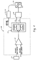
- Figure 4 is a schematic showing a closed loop circuit or control mechanism 120 that is used to control the continuously variable aperture of Figures 2 and 3.
- the mechanism 120 may be implemented in either software or hardware.
- Inputs to the circuit 120 are the desired ion beam current as defined by the particular recipe being run, an ion beam current measurement provided by second flag Faraday 35, and an aperture position indication provided by the linear potentiometer 116, 118.
- the output of the circuit 120 is a control signal or signals provided to the DC motor 82 to control movement of the control arms and thus the gap 50 of the aperture 44.
- a comparator 122 compares the desired ion beam current with the measured beam current from the second flag Faraday 35. This beam current information is provided every 50 milliseconds and is stored in a software database. The output of the comparator is input into a motor controller 124 including control logic that controls the motor 82 based on whether the measured ion beam current is greater than or less than the desired ion beam current. If the measured ion beam current is greater than the desired ion beam current, the motor controller issues a first control signal 126 to the DC motor to rotate in a first direction to move the aperture plates 44A and 44B closer together. Thus, the aperture gap 50 is narrowed, and less ion beam current is delivered to the linac 18.
- the motor controller issues a second control signal 128 to the DC motor to rotate in a second direction (opposite the first direction) to move the aperture plates 44A and 44B further apart.
- the aperture gap 50 is widened, and more ion beam current is delivered to the linac 18.
- the motor controller 124 is provided with an aperture position feedback signal from the linear potentiometer 116, 118. (As such, the control circuit 120 operates in a closed loop manner.)
- the aperture control mechanism of Figure 4 is part of an overall control algorithm utilized for tuning the ion beam current of the ion implanter of Figure 1 based on desired operating parameters and sensed operating conditions.
- a schematic flow chart representing this overall control algorithm 130 which may be implemented in hardware or software, is shown in Figure 5.
- a first step 132 of the system tuning method 130 involves closing the first flag Faraday 31 by positioning the flag in the path of the ion beam, as is known in the art, at the location immediately downstream of the continuously variable aperture 30.
- the position of the aperture 44 is preset, which comprises setting the gap 50 of the aperture based on implanter past operational history.
- the linac 18 is preset to desired operating parameters.
- Decision 138 involves measuring the ion beam current with the first flag Faraday 31. If the beam current is within an acceptable range, such that fine tuning of the continuously variable aperture 30 will result in an acceptable beam current measured downstream at the second flag Faraday 35, the first flag Faraday 31 is opened in step 140 and the ion beam is permitted to travel through the aperture 30 and into the linac 18. If, however, the beam current measured by the first flag Faraday 31 is outside of the acceptable range, such that tuning the continuously variable aperture 30 will not result in an acceptable beam current measured downstream at the second flag Faraday 35, the aperture 44 position must be adjusted ( i.e ., coarsely tuned) in step 142.
- the first flag Faraday 31 is opened. If, however, the beam current measured by the first flag Faraday 31 is still outside the acceptable range, the ion beam source 14 must be re-tuned in step 146. After re-tuning the source 14, if at decision 148 the beam current measured by the first flag Faraday is within the acceptable range, the first flag Faraday 31 is opened. If, however, the beam current measured by the first flag Faraday 31 is still outside the acceptable range, the ion beam source 14 must again be re-tuned in step 146.
- the loop provided by steps 146 and 148 is not infinite in nature as a time-out mechanism is provided should the source 14 prove to be not tunable to the desired current output.
- step 150 the injector 12 is tuned for alignment of the beam into the linac 18.
- Decision 152 involves measuring the ion beam current with the second flag Faraday 35. If the beam current is within an acceptable range, system tuning is complete at step 154 and second flag Faraday 35 may be opened. If, however, the beam current is not within the acceptable range, the aperture gap 50 must be fine-tuned at step 156 by invoking the closed loop circuit or control mechanism 120 of Figure 4. Because circuit 120 is closed loop, the aperture position will be continuously adjusted until the measured beam current at second flag Faraday 35 is within the acceptable range. At this point, system tuning is complete at step 154 and second flag Faraday may be opened.
- the position of the aperture 44 may be controlled to a fineness of about 5 microns ( ⁇ m) (i.e ., each control arm moving it respective aperture plate 2.5 microns ( ⁇ m)), which may correspond to a mere .1% change in the beam current. That is, assuming that the beam current is homogenous across the width of the aperture gap 50, and, for example, with an injected current of 100 microamps ( ⁇ A) with the aperture 44 fully open, the beam current may be controlled downward in steps as little as 1 microamp ( ⁇ A).
- circuit 120 looks at desired beam current, measured beam current (from second flag Faraday 35), and aperture position (from either the linear potentiometer or rotary encoder). The comparison of measured and desired beam current is made at least once each second in the preferred mode of operation.
- Figures 6 and 7 are graphical representations of beam current response to the adjustment of the aperture position using the logic of Figure 4.
- Figure 6 is based on a first preferred control method, referred to herein as the asymptotic method.
- Figure 7 is based on a second preferred control method, referred to as the bi-section method.
- an error signal is generated by circuit 120 based on the difference between the desired beam current versus actual beam current.
- the present aperture position is determined based on potentiometer or encoder feedback. If measured current is greater than desired current (not shown), control signal 126 is generated to narrow the aperture gap 50 by rotating the motor 82 in one direction, and if measured current is less than desired current (Figure 6), control signal 128 is generated to widen the aperture gap 50 by rotating the motor 82 in the other direction.
- Aperture position feedback may be used so that the control circuit 120 can determine the present aperture position and the estimated required aperture position.
- the speed at which the motor 82 is driven, and hence at which the aperture is widened or narrowed, depends on the magnitude of the error signal and the aperture position.
- the motor is driven at a faster rate.
- the magnitude of the error signal becomes progressively smaller, and the motor is driven slower.
- the motor is prematurely instructed to stop to accommodate momentum within the system.
- the measured current shown in Figure 6 does not overshoot its desired beam current target but instead asymptotically approaches the beam current target.
- a comparison is made by circuit 120 of desired beam current versus actual beam current.
- the present aperture position is determined based on potentiometer or encoder feedback. If measured current is greater than desired current (not shown), control signal 126 is generated to narrow the aperture gap 50 by rotating the motor 82 in one direction, and if measured current is less than desired current (Figure 7), control signal 128 is generated to widen the aperture gap 50 by rotating the motor 82 in the other direction.
- the motor 82 is instructed to move the aperture from its position at t 1 to a position at t 2 which represents half the maximum distance it could move in the correct direction.
- the potentiometer or encoder indicates that the aperture is at position 20 (with position 0 indicating fully closed and position 100 indicating fully open), and measured beam current is less than desired beam current, the motor 82 is instructed to move from position 20 (nearly closed) to position 60 (at least half open).
- the 40 increment widening of the gap represents half of the difference between the present position 20 and the fully open position 100.
- a second comparison is made by circuit 120 of desired beam current versus actual beam current. Again the present aperture position (60) is determined. In the case of Figure 7, the desired beam current has been exceeded (overshot) and thus the motor 82 is instructed to close to position 40 (half the distance between the present position 60 and the original position 20).
- a third comparison is made and aperture position (40) is determined. As shown in Figure 7, the desired beam current has been undershot and thus the motor 82 is instructed to open to position 50 (half the distance between the present position 40 and the previous position 60).
- a fourth comparison is made and, because measured beam current is now within an acceptable range, the aperture position remains fixed at position 50.
- the beam current may be tuned for a particular recipe within a very short time, on the order of 20 seconds. This time is contrasted to that required to re-tune the source if the continuously variable aperture is not used, which has been found to be on the order of two to three minutes.
- the present invention provides an efficient, rapid mechanism for tuning the ion beam current in the implanter 10.
Landscapes
- Chemical & Material Sciences (AREA)
- Analytical Chemistry (AREA)
- Physical Vapour Deposition (AREA)
- Particle Accelerators (AREA)
- Electron Sources, Ion Sources (AREA)
Abstract
Description
Claims (23)
- A variable aperture (30) for controlling the amount of ion beam current passing therethrough in an ion implantation system (10), comprising:(i) an aperture (44) defined by opposing first and second aperture plates (44A, 44B) through which an ion beam passes;(ii) control arms (46A, 46B) connected, respectively, to said first and second aperture plates (44A, 44B);(iii) an aperture drive mechanism (36) for simultaneously imparting movement to said control arms in opposite directions, each of said opposite directions being generally perpendicular to an axis along which the ion beam passes, to adjust a gap (50) between said aperture plates (44A, 44B) to thereby control the amount of current passing through said aperture (44).
- The variable aperture (30) of claim 1, wherein said aperture drive mechanism (36) comprises a threaded shaft (84) driven by a motor (82), said threaded shaft having oppositely threaded portions (84A, 84B) coupled, respectively, to said control arms (46B, 46A), such that rotation of said shaft by said motor imparts simultaneous movement of said control arms in opposite directions.
- The variable aperture (30) of claim 1, wherein said aperture drive mechanism (36) comprises a rack and pinion assembly, said pinion coupled to a motor and said rack coupled to said control arms (46A, 46B).
- The variable aperture (30) of claim 1, further comprising a feedback mechanism (116, 118) for providing an indication of control arm position.
- The variable aperture (30) of claim 2, wherein said control arms (46A, 46B) are movable in opposite directions by said aperture drive mechanism (36) in increments of about 2.5 microns (µm).
- The variable aperture (30) of claim 4, wherein said feedback mechanism (116, 118) comprises a linear potentiometer coupled to said control anus (46A, 46B).
- The variable aperture (30) of claim 4, wherein said feedback mechanism (116, 118) comprises a rotary encoder coupled to said aperture drive mechanism (36).
- The variable aperture (30) of claim 4, wherein said aperture plates (44A, 44B) are constructed from graphite.
- The variable aperture (30) of claim 4, wherein said control arms (44A, 44B) are water-cooled.
- The variable aperture (30) of claim 4, wherein the angle (α) between an axis (51) parallel to which the control arms move, and an axis (49) of the gap (50) between the aperture plates, is made adjustable.
- An implanter beamline assembly (14, 16, 18, 30) for a high energy ion implanter (10), comprising:(i) an ion source (14) for generating an ion beam;(ii) a mass analysis magnet (16) for mass analyzing the ion beam generated by the ion source;(iii) a linear accelerator (18) for accelerating the ion beam analyzed by the mass analysis magnet; and(iv) a variable aperture assembly (30) disposed between said mass analysis magnet (16) and said liner accelerator (18), said variable aperture comprising an aperture (44) through which the ion beam passes, said aperture (44) having a width which is variable to control the amount of ion beam current passing therethrough.
- The implanter beamline assembly (14, 16, 18, 30) of claim 10, wherein said aperture (44) is defined by opposing first and second aperture plates (44A, 44B) through which the ion beam passes, and wherein said variable aperture assembly (30) further comprises control arms (46A, 46B) connected, respectively, to said first and second aperture plates (44A, 44B), and an aperture drive mechanism (36) for simultaneously imparting movement to said control arms in opposite directions, each of said opposite directions being generally perpendicular to an axis along which the ion beam passes, to adjust a gap (50) between said aperture plates (44A, 44B) to thereby control the amount of current passing through said aperture (44).
- The implanter beamline assembly (14, 16, 18, 30) of claim 12, wherein said control arms (46A, 46B) are movable in opposite directions by said aperture drive mechanism (36) in increments of about 2.5 microns (µm).
- The implanter beamline assembly (14, 16, 18, 30) of claim 12, wherein said aperture (44) is disposed inside the beamline assembly and operates under vacuum conditions, said aperture drive mechanism (36)is disposed outside of the beamline assembly and operates under ambient atmospheric pressure conditions, and said control arms (44A, 44B) pass through a plate (34) that forms the interface between the inside and the outside of the beamline assembly.
- The implanter beamline assembly (14, 16, 18, 30) of claim 14, further comprising expansible steel bellows (70, 80) located at the interface of the control arms (46A, 46B) and the exterior of the plate (34) to maintain vacuum conditions inside the beamline assembly, while permitting the control arms to move through the plate.
- The implanter beamline assembly (14, 16, 18, 30) of claim 14, further comprising a feedback mechanism (116, 118) for providing an indication of control arm position.
- The implanter beamline assembly (14, 16, 18, 30) of claim 14, wherein said aperture drive mechanism (36) comprises a threaded shaft (84) driven by motor (82), said threaded shaft having oppositely threaded portions (84A, 84B) coupled, respectively, to said control arms (46B, 46A), such tat rotation of said shalt by said motor imparts simultaneous movement of said control arms in opposite directions.
- The implanter beamline assembly (14, 16, 18, 30) of claim 14, wherein said aperture plates (44A, 44B) are constructed from graphite.
- The implanter beamline assembly (14, 16, 18, 30) of claim 14, wherein said control arms (44A, 44B) are water-cooled.
- A control system (120) for adjusting the width (50) of an aperture (44) through which an ion beam passes in an ion implanter (10), the implanter including a beam current detection device (35), an aperture position detection device (116, 118), and an aperture movement mechanism for imparting movement to the aperture (44) to adjust the width (50) thereof, the control system comprising:(i) a first input for receiving a first input signal from said current detection device (35) representing actual ion beam current passing through the implanter;(ii) a second input for receiving a second input representing a desired ion beam current;(iii) a third input for receiving a third input signal from said position detection device (116, 118) representing aperture position;(iv) an output for outputting control signals (126, 128) to the aperture movement mechanism; and(v) control logic (122, 124) for determining said output control signals based on said first, second, and third inputs.
- The control system (120) of claim 20, wherein said aperture movement mechanism comprises a motor (82) driving a aperture drive mechanism (36), said aperture drive mechanism being coupled to said aperture (44) by means of control arms (46A, 46B).
- The control system (120) of claim 20, wherein said aperture drive mechanism (36) comprises a threaded shaft (84) driven by motor (82), said threaded shaft having oppositely threaded portions (84A, 84B) coupled, respectively, to said control arms (46B, 46A), such that rotation of said shaft by said motor imparts simultaneous movement of said control arms in opposite directions.
- The control system (120) of claim 20, wherein said control arms (46A, 46B) are movable in opposite directions by said aperture drive mechanism (36) in increments of about 2.5 microns (µm).
Applications Claiming Priority (2)
| Application Number | Priority Date | Filing Date | Title |
|---|---|---|---|
| US253375 | 1999-02-19 | ||
| US09/253,375 US6207964B1 (en) | 1999-02-19 | 1999-02-19 | Continuously variable aperture for high-energy ion implanter |
Publications (3)
| Publication Number | Publication Date |
|---|---|
| EP1030344A2 true EP1030344A2 (en) | 2000-08-23 |
| EP1030344A3 EP1030344A3 (en) | 2001-05-02 |
| EP1030344B1 EP1030344B1 (en) | 2004-12-08 |
Family
ID=22960006
Family Applications (1)
| Application Number | Title | Priority Date | Filing Date |
|---|---|---|---|
| EP00301220A Expired - Lifetime EP1030344B1 (en) | 1999-02-19 | 2000-02-16 | Continuously variable aperture for high-energy ion implanter |
Country Status (7)
| Country | Link |
|---|---|
| US (1) | US6207964B1 (en) |
| EP (1) | EP1030344B1 (en) |
| JP (1) | JP4915490B2 (en) |
| KR (1) | KR100485534B1 (en) |
| DE (1) | DE60016481T2 (en) |
| SG (1) | SG82676A1 (en) |
| TW (1) | TW590318U (en) |
Cited By (3)
| Publication number | Priority date | Publication date | Assignee | Title |
|---|---|---|---|---|
| WO2006133041A3 (en) * | 2005-06-03 | 2007-11-22 | Axcelis Tech Inc | Beam stop and beam tuning methods |
| CN104658843A (en) * | 2013-11-21 | 2015-05-27 | 斯伊恩股份有限公司 | High Energy Ion Implanter, Beam Current Adjuster, And Beam Current Adjustment Method |
| CN110164582A (en) * | 2019-05-31 | 2019-08-23 | 钱铁威 | A kind of neutrons collimation device that fast neutron beam diameter can be adjusted |
Families Citing this family (25)
| Publication number | Priority date | Publication date | Assignee | Title |
|---|---|---|---|---|
| US6507033B1 (en) * | 1999-03-29 | 2003-01-14 | The Regents Of The University Of California | Versatile, high-sensitivity faraday cup array for ion implanters |
| US6501078B1 (en) * | 2000-03-16 | 2002-12-31 | Applied Materials, Inc. | Ion extraction assembly |
| US6320334B1 (en) * | 2000-03-27 | 2001-11-20 | Applied Materials, Inc. | Controller for a linear accelerator |
| US6885014B2 (en) * | 2002-05-01 | 2005-04-26 | Axcelis Technologies, Inc. | Symmetric beamline and methods for generating a mass-analyzed ribbon ion beam |
| US6703628B2 (en) | 2000-07-25 | 2004-03-09 | Axceliss Technologies, Inc | Method and system for ion beam containment in an ion beam guide |
| US6664548B2 (en) | 2002-05-01 | 2003-12-16 | Axcelis Technologies, Inc. | Ion source and coaxial inductive coupler for ion implantation system |
| US6664547B2 (en) | 2002-05-01 | 2003-12-16 | Axcelis Technologies, Inc. | Ion source providing ribbon beam with controllable density profile |
| US6828572B2 (en) * | 2003-04-01 | 2004-12-07 | Axcelis Technologies, Inc. | Ion beam incident angle detector for ion implant systems |
| US6891174B2 (en) * | 2003-07-31 | 2005-05-10 | Axcelis Technologies, Inc. | Method and system for ion beam containment using photoelectrons in an ion beam guide |
| US20050061997A1 (en) * | 2003-09-24 | 2005-03-24 | Benveniste Victor M. | Ion beam slit extraction with mass separation |
| US7674687B2 (en) * | 2005-07-27 | 2010-03-09 | Silicon Genesis Corporation | Method and structure for fabricating multiple tiled regions onto a plate using a controlled cleaving process |
| US7863157B2 (en) * | 2006-03-17 | 2011-01-04 | Silicon Genesis Corporation | Method and structure for fabricating solar cells using a layer transfer process |
| WO2007118121A2 (en) | 2006-04-05 | 2007-10-18 | Silicon Genesis Corporation | Method and structure for fabricating solar cells using a layer transfer process |
| US8153513B2 (en) * | 2006-07-25 | 2012-04-10 | Silicon Genesis Corporation | Method and system for continuous large-area scanning implantation process |
| US7629597B2 (en) * | 2006-08-18 | 2009-12-08 | Axcelis Technologies, Inc. | Deposition reduction system for an ion implanter |
| US20080128641A1 (en) * | 2006-11-08 | 2008-06-05 | Silicon Genesis Corporation | Apparatus and method for introducing particles using a radio frequency quadrupole linear accelerator for semiconductor materials |
| US20090206275A1 (en) * | 2007-10-03 | 2009-08-20 | Silcon Genesis Corporation | Accelerator particle beam apparatus and method for low contaminate processing |
| US20110049383A1 (en) * | 2009-09-03 | 2011-03-03 | Advanced Ion Beam Technology, Inc. | Ion implanter and ion implant method thereof |
| US8987691B2 (en) | 2009-09-03 | 2015-03-24 | Advanced Ion Beam Technology, Inc. | Ion implanter and ion implant method thereof |
| US8198610B2 (en) * | 2009-10-20 | 2012-06-12 | Advanced Ion Beam Technology, Inc. | Ion implanter with variable aperture and ion implant method thereof |
| US8669539B2 (en) * | 2010-03-29 | 2014-03-11 | Advanced Ion Beam Technology, Inc. | Implant method and implanter by using a variable aperture |
| US8309444B2 (en) | 2010-07-07 | 2012-11-13 | Taiwan Semiconductor Manufacturing Company, Ltd. | System and method of dosage profile control |
| US9953801B1 (en) | 2016-11-29 | 2018-04-24 | Axcelis Technologies, Inc. | Two-axis variable width mass resolving aperture with fast acting shutter motion |
| CN107195518A (en) * | 2017-06-22 | 2017-09-22 | 京东方科技集团股份有限公司 | Ion implanting quantity regulating device and method, ion implantation device, determination methods |
| CN112758696B (en) * | 2021-01-19 | 2023-07-11 | 埃特曼半导体技术有限公司 | Vacuum sample driving device |
Family Cites Families (16)
| Publication number | Priority date | Publication date | Assignee | Title |
|---|---|---|---|---|
| GB1518282A (en) * | 1974-07-31 | 1978-07-19 | Atomic Energy Authority Uk | Ion beam separators |
| US4017403A (en) | 1974-07-31 | 1977-04-12 | United Kingdom Atomic Energy Authority | Ion beam separators |
| JPS62272437A (en) | 1986-05-21 | 1987-11-26 | Mitsubishi Electric Corp | Mass spectrometer for ion implanting apparatus |
| JPS63304563A (en) * | 1987-06-03 | 1988-12-12 | Hitachi Ltd | Ion implantation |
| JPH02295040A (en) * | 1989-05-10 | 1990-12-05 | Hitachi Ltd | Focused ion beam device |
| US5063294A (en) * | 1989-05-17 | 1991-11-05 | Kabushiki Kaisha Kobe Seiko Sho | Converged ion beam apparatus |
| DE3917153A1 (en) * | 1989-05-26 | 1990-11-29 | Boehringer Mannheim Gmbh | NEW DIPHOSPHONIC ACID DERIVATIVES, METHOD FOR THE PRODUCTION THEREOF AND MEDICINAL PRODUCTS CONTAINING THESE COMPOUNDS |
| JPH04132005A (en) * | 1990-09-20 | 1992-05-06 | Hitachi Metals Ltd | Floating type magnetic head |
| JP3034009B2 (en) * | 1990-10-22 | 2000-04-17 | 株式会社日立製作所 | Ion implantation equipment |
| US5130552A (en) | 1990-12-17 | 1992-07-14 | Applied Materials, Inc. | Improved ion implantation using a variable mass resolving system |
| JP3365066B2 (en) * | 1994-04-27 | 2003-01-08 | 日新電機株式会社 | Ion implantation method and apparatus therefor |
| GB9515090D0 (en) * | 1995-07-21 | 1995-09-20 | Applied Materials Inc | An ion beam apparatus |
| JPH0945274A (en) * | 1995-07-31 | 1997-02-14 | Nissin Electric Co Ltd | Device for correcting dose of ion implanter |
| JPH1021841A (en) * | 1996-06-27 | 1998-01-23 | Nissin Electric Co Ltd | Ion beam building up method |
| US5780863A (en) * | 1997-04-29 | 1998-07-14 | Eaton Corporation | Accelerator-decelerator electrostatic lens for variably focusing and mass resolving an ion beam in an ion implanter |
| US5998798A (en) * | 1998-06-11 | 1999-12-07 | Eaton Corporation | Ion dosage measurement apparatus for an ion beam implanter and method |
-
1999
- 1999-02-19 US US09/253,375 patent/US6207964B1/en not_active Expired - Lifetime
-
2000
- 2000-02-09 SG SG200000743A patent/SG82676A1/en unknown
- 2000-02-09 TW TW093203137U patent/TW590318U/en not_active IP Right Cessation
- 2000-02-16 EP EP00301220A patent/EP1030344B1/en not_active Expired - Lifetime
- 2000-02-16 DE DE60016481T patent/DE60016481T2/en not_active Expired - Lifetime
- 2000-02-17 JP JP2000039408A patent/JP4915490B2/en not_active Expired - Lifetime
- 2000-02-19 KR KR10-2000-0008027A patent/KR100485534B1/en not_active Expired - Lifetime
Cited By (10)
| Publication number | Priority date | Publication date | Assignee | Title |
|---|---|---|---|---|
| WO2006133041A3 (en) * | 2005-06-03 | 2007-11-22 | Axcelis Tech Inc | Beam stop and beam tuning methods |
| US7547898B2 (en) | 2005-06-03 | 2009-06-16 | Axcelis Technologies, Inc. | Particulate prevention in ion implantation |
| US7547899B2 (en) | 2005-06-03 | 2009-06-16 | Axcelis Technologies, Inc. | Charged beam dump and particle attractor |
| US7579604B2 (en) | 2005-06-03 | 2009-08-25 | Axcelis Technologies Inc. | Beam stop and beam tuning methods |
| CN101238538B (en) * | 2005-06-03 | 2011-07-13 | 艾克塞利斯技术公司 | Beam stop and beam tuning methods |
| KR101306541B1 (en) * | 2005-06-03 | 2013-09-17 | 액셀리스 테크놀로지스, 인크. | Beam stop and beam tuning methods |
| TWI426541B (en) * | 2005-06-03 | 2014-02-11 | Axcelis Tech Inc | Beam blocking assembly for mass analyzer, ion implantation system, and method for preventing particle contamination in an ion implantation system |
| CN104658843A (en) * | 2013-11-21 | 2015-05-27 | 斯伊恩股份有限公司 | High Energy Ion Implanter, Beam Current Adjuster, And Beam Current Adjustment Method |
| CN104658843B (en) * | 2013-11-21 | 2018-01-16 | 斯伊恩股份有限公司 | High energy ion injection device, beam current adjusting apparatus and beam current method of adjustment |
| CN110164582A (en) * | 2019-05-31 | 2019-08-23 | 钱铁威 | A kind of neutrons collimation device that fast neutron beam diameter can be adjusted |
Also Published As
| Publication number | Publication date |
|---|---|
| SG82676A1 (en) | 2001-08-21 |
| EP1030344B1 (en) | 2004-12-08 |
| KR100485534B1 (en) | 2005-04-27 |
| US6207964B1 (en) | 2001-03-27 |
| DE60016481T2 (en) | 2005-12-15 |
| KR20000058112A (en) | 2000-09-25 |
| JP4915490B2 (en) | 2012-04-11 |
| EP1030344A3 (en) | 2001-05-02 |
| DE60016481D1 (en) | 2005-01-13 |
| TW590318U (en) | 2004-06-01 |
| JP2000243342A (en) | 2000-09-08 |
Similar Documents
| Publication | Publication Date | Title |
|---|---|---|
| EP1030344B1 (en) | Continuously variable aperture for high-energy ion implanter | |
| EP1030343B1 (en) | Method & system for operating a variable aperture in an ion implanter | |
| US4667111A (en) | Accelerator for ion implantation | |
| US6423976B1 (en) | Ion implanter and a method of implanting ions | |
| US5834786A (en) | High current ribbon beam ion implanter | |
| US9390889B2 (en) | Ion implanter and method of ion beam tuning | |
| US20090236547A1 (en) | Extraction electrode system for high current ion implanter | |
| WO1998002900A9 (en) | High current ribbon beam ion implanter | |
| EP0942453A2 (en) | Monitoring of plasma constituents using optical emission spectroscopy | |
| US5696382A (en) | Ion-implanter having variable ion beam angle control | |
| JPH06132005A (en) | Improved ion implantation | |
| KR20040014474A (en) | Methods and apparatus for scanned beam uniformity adjustment in ion implanters | |
| CN109997210B (en) | Snap-action shading kinematic dual-axis variable-width mass-resolving aperture | |
| US20060097196A1 (en) | Dose uniformity during scanned ion implantation | |
| EP1581962B1 (en) | Mounting mechanism for plasma extraction aperture | |
| KR101819972B1 (en) | Optimizing device and optimizing method of the particle accelerator | |
| US9269536B2 (en) | Double ended electrode manipulator | |
| WO2023014889A1 (en) | Blended energy ion implantation | |
| JPH03219544A (en) | Charged particle implanting device | |
| EP0701268A1 (en) | Ion implantation apparatus | |
| US6703627B2 (en) | Real time monitor method and system for extraction electrode | |
| US20250336642A1 (en) | Energy accuracy for an rf linear accelerator ion implantation system | |
| Lopes et al. | Automation of a particle accelerator operation using LabVIEW | |
| He et al. | Physics design, fabrication, RF measurement and beam commissioning of a dual beam drift tube linac | |
| JPS62271339A (en) | Ion implantation device |
Legal Events
| Date | Code | Title | Description |
|---|---|---|---|
| PUAI | Public reference made under article 153(3) epc to a published international application that has entered the european phase |
Free format text: ORIGINAL CODE: 0009012 |
|
| AK | Designated contracting states |
Kind code of ref document: A2 Designated state(s): DE FR GB IT NL |
|
| AX | Request for extension of the european patent |
Free format text: AL;LT;LV;MK;RO;SI |
|
| PUAL | Search report despatched |
Free format text: ORIGINAL CODE: 0009013 |
|
| AK | Designated contracting states |
Kind code of ref document: A3 Designated state(s): AT BE CH CY DE DK ES FI FR GB GR IE IT LI LU MC NL PT SE |
|
| AX | Request for extension of the european patent |
Free format text: AL;LT;LV;MK;RO;SI |
|
| RIC1 | Information provided on ipc code assigned before grant |
Free format text: 7H 01J 37/09 A, 7H 01J 37/304 B, 7H 01J 37/317 B, 7G 21K 1/04 B |
|
| 17P | Request for examination filed |
Effective date: 20010502 |
|
| AKX | Designation fees paid |
Free format text: DE FR GB IT NL |
|
| 17Q | First examination report despatched |
Effective date: 20030213 |
|
| GRAP | Despatch of communication of intention to grant a patent |
Free format text: ORIGINAL CODE: EPIDOSNIGR1 |
|
| GRAS | Grant fee paid |
Free format text: ORIGINAL CODE: EPIDOSNIGR3 |
|
| GRAA | (expected) grant |
Free format text: ORIGINAL CODE: 0009210 |
|
| AK | Designated contracting states |
Kind code of ref document: B1 Designated state(s): DE FR GB IT NL |
|
| REG | Reference to a national code |
Ref country code: GB Ref legal event code: FG4D |
|
| REF | Corresponds to: |
Ref document number: 60016481 Country of ref document: DE Date of ref document: 20050113 Kind code of ref document: P |
|
| PLBE | No opposition filed within time limit |
Free format text: ORIGINAL CODE: 0009261 |
|
| STAA | Information on the status of an ep patent application or granted ep patent |
Free format text: STATUS: NO OPPOSITION FILED WITHIN TIME LIMIT |
|
| ET | Fr: translation filed | ||
| 26N | No opposition filed |
Effective date: 20050909 |
|
| PGFP | Annual fee paid to national office [announced via postgrant information from national office to epo] |
Ref country code: NL Payment date: 20070108 Year of fee payment: 8 |
|
| PGFP | Annual fee paid to national office [announced via postgrant information from national office to epo] |
Ref country code: IT Payment date: 20070526 Year of fee payment: 8 |
|
| PGFP | Annual fee paid to national office [announced via postgrant information from national office to epo] |
Ref country code: GB Payment date: 20080108 Year of fee payment: 9 |
|
| NLV4 | Nl: lapsed or anulled due to non-payment of the annual fee |
Effective date: 20080901 |
|
| PG25 | Lapsed in a contracting state [announced via postgrant information from national office to epo] |
Ref country code: NL Free format text: LAPSE BECAUSE OF NON-PAYMENT OF DUE FEES Effective date: 20080901 |
|
| PG25 | Lapsed in a contracting state [announced via postgrant information from national office to epo] |
Ref country code: IT Free format text: LAPSE BECAUSE OF NON-PAYMENT OF DUE FEES Effective date: 20080216 |
|
| GBPC | Gb: european patent ceased through non-payment of renewal fee |
Effective date: 20090216 |
|
| PG25 | Lapsed in a contracting state [announced via postgrant information from national office to epo] |
Ref country code: GB Free format text: LAPSE BECAUSE OF NON-PAYMENT OF DUE FEES Effective date: 20090216 |
|
| PGFP | Annual fee paid to national office [announced via postgrant information from national office to epo] |
Ref country code: FR Payment date: 20120203 Year of fee payment: 13 |
|
| PGFP | Annual fee paid to national office [announced via postgrant information from national office to epo] |
Ref country code: DE Payment date: 20120229 Year of fee payment: 13 |
|
| REG | Reference to a national code |
Ref country code: FR Ref legal event code: ST Effective date: 20131031 |
|
| REG | Reference to a national code |
Ref country code: DE Ref legal event code: R119 Ref document number: 60016481 Country of ref document: DE Effective date: 20130903 |
|
| PG25 | Lapsed in a contracting state [announced via postgrant information from national office to epo] |
Ref country code: DE Free format text: LAPSE BECAUSE OF NON-PAYMENT OF DUE FEES Effective date: 20130903 Ref country code: FR Free format text: LAPSE BECAUSE OF NON-PAYMENT OF DUE FEES Effective date: 20130228 |