EP1030261A1 - Dispositif de lecture optique d'information portées par un support tel qu'un ticket de jeu - Google Patents
Dispositif de lecture optique d'information portées par un support tel qu'un ticket de jeu Download PDFInfo
- Publication number
- EP1030261A1 EP1030261A1 EP00400422A EP00400422A EP1030261A1 EP 1030261 A1 EP1030261 A1 EP 1030261A1 EP 00400422 A EP00400422 A EP 00400422A EP 00400422 A EP00400422 A EP 00400422A EP 1030261 A1 EP1030261 A1 EP 1030261A1
- Authority
- EP
- European Patent Office
- Prior art keywords
- reading
- optical
- information
- support
- ticket
- Prior art date
- Legal status (The legal status is an assumption and is not a legal conclusion. Google has not performed a legal analysis and makes no representation as to the accuracy of the status listed.)
- Withdrawn
Links
Images

Classifications
-
- G—PHYSICS
- G06—COMPUTING OR CALCULATING; COUNTING
- G06K—GRAPHICAL DATA READING; PRESENTATION OF DATA; RECORD CARRIERS; HANDLING RECORD CARRIERS
- G06K7/00—Methods or arrangements for sensing record carriers, e.g. for reading patterns
- G06K7/10—Methods or arrangements for sensing record carriers, e.g. for reading patterns by electromagnetic radiation, e.g. optical sensing; by corpuscular radiation
- G06K7/10544—Methods or arrangements for sensing record carriers, e.g. for reading patterns by electromagnetic radiation, e.g. optical sensing; by corpuscular radiation by scanning of the records by radiation in the optical part of the electromagnetic spectrum
- G06K7/10821—Methods or arrangements for sensing record carriers, e.g. for reading patterns by electromagnetic radiation, e.g. optical sensing; by corpuscular radiation by scanning of the records by radiation in the optical part of the electromagnetic spectrum further details of bar or optical code scanning devices
- G06K7/10861—Methods or arrangements for sensing record carriers, e.g. for reading patterns by electromagnetic radiation, e.g. optical sensing; by corpuscular radiation by scanning of the records by radiation in the optical part of the electromagnetic spectrum further details of bar or optical code scanning devices sensing of data fields affixed to objects or articles, e.g. coded labels
Definitions
- the invention relates to a device for optical reading of carried information. by a medium such as a game ticket.
- Game tickets to use this example again, are mainly divided into two categories: scratch tickets to discover a gain and tickets to complete to bet on a horse race, on a combination of figures and other issues.
- Game ticket distributors generally use a optical reading, allowing them to read information carried by a ticket, for example to check its validity.
- Information to read for example a barcode, can be worn on one or both sides of the ticket. In the latter case, the ticket must be returned between the respective readings on both sides, either manually by the distributor or using a turning mechanism integrated in the device.
- the present invention aims to facilitate the reading of both sides of a ticket game, and more generally of an information medium.
- the invention relates to an optical reading device of information carried by the two sides, rear and front, of a support information, comprising means for receiving the medium in the device, optical reading means, axis reflection means reading means and means arranged so that the support information and the optical reading means are trained in relative movement to read information from the front of the support, for reflection on said reflection means, and to read directly the information from the rear face of the support, the support intercepting the beam reading optics of the front face of the support, characterized in that the support receiving means are arranged so that the support is inclined on the axis of the reading means and said reflecting means comprise a single mirror.
- the information carried by the two faces of the support are read without reversing it.
- Front panel information are read by reflection of a reading optical beam on the mirror, and the rear panel information is read after beam interception optics for reading the front face by the support itself.
- a mechanism is provided drive in relative movement of the information carrier and optical reading means.
- a reception passage for the information medium arranged for said medium to move from the entrance towards the exit under the effect of its own weight.
- the optical reading means comprise a sensor optics associated with an optical system with great depth of field.
- the optical reading means can thus include a CCD (Charged Coupled Device) sensor dump).
- CCD Charge Coupled Device
- the device includes a window for reading a support. of information external to the device.
- a shutter for closing said window is provided, movable between an open reading position of an information carrier external to the device and a closed position for reading a support internal information.
- the optical reading device is intended to read information, here bar codes, carried on both sides, rear and front, of a support information consisting, in the particular example of the description, of a game ticket.
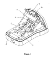
- the device comprises, in a housing comprising a chassis 3 and a cover protective top not shown, an optical reading assembly 1 and a set 2 for receiving a game ticket.
- the optical reading assembly 1 and the set of reception 2 are respectively located at the rear and at the front of the device.
- the rear face and the front face of a game ticket get along respectively from the rear-facing side of the device, and from the side opposite, facing forward.
- the optical reading assembly 1 comprises an optical sensor 4, in this case a CCD (Charge Coupled Device) sensor, associated with an optical module 6, attached to the front of the CCD sensor 4.
- An optical sensor 4 in this case a CCD (Charge Coupled Device) sensor, associated with an optical module 6, attached to the front of the CCD sensor 4.
- a transparent glass 12 is interposed between the CCD sensor 4 and the module optics 6.
- CCD sensor 4 includes a strip of photodetection elements extending perpendicular to the plane of Figures 1 and 2, in a surface detection 5, and has an optical resolution compatible with the width elementary bars of bar codes to read, in other words allowing it distinguish two adjacent elementary bars from a barcode.
- the optical module 6 comprises, inside a housing 7, a lens, or optical system 8, of optical axis 9, intended to focus optical beams of reading substantially in an image plane P im perpendicular to the axis optic 9, in which the detection surface 5 of the CCD sensor 4 extends.
- the optical system 8 comprises a front entrance pupil 10 and a rear exit pupil 11, here distant from each other by 8, 3 mm (millimeters) along the optical axis 9.
- the exit pupil 11 is located at a distance of 24.69 mm, along the optical axis 9, from the image plane P im .
- the optical system is manufactured by the company FUJINON, and available under the reference FAQ18 / 25. Its characteristics, supplied by the manufacturer, are contained in the following table.
- Depth of field (PC) ⁇ 35 mm around a plane located 190 mm from the image plane P im , along the optical axis
- Depth of field designates the distance between two object planes limits perpendicular to the optical axis 9, between which the resolution optical, or FTM, is greater than a given value, here equal to 40% for 2 cycles / mm on the object plane.
- the term "n" means the optical index of the material constituting the glass.
- the depth of field of the optical system 8 can vary more or less 35mm around an object plane located 190mm from the image plane P im , along the optical axis 9, for sufficient optical resolution, represented by the FTM.
- the optical resolution of the optical reading assembly 1 being limited by that of the optical system 8, the optical reading assembly 1 can read, with sufficient optical resolution, bar codes positioned in planes objects located between two planes boundary objects respectively located at 155 mm and at 225 mm from the image plane P im , along the optical axis 9.
- the optical reading assembly 1 is connected to a system for processing information read by the CCD sensor 4, not shown, intended to interpret the information read and coded in black and white.
- the system 2 for receiving a game ticket comprises, between an entry upper 14 for introduction and a lower outlet 15 for ejecting a ticket of play, a passage 16 for receipt of the ticket.
- a drive mechanism for moving a game ticket is arranged in the vicinity of the entrance 14 and comprises a roller gripping and driving the ticket, rotatably mounted and pressing against a support plate in the receiving passage 16.
- a window 13 for receiving a game ticket extends along the reception passage 16, through the optical axis 9, in a plane here slightly inclined backwards on the optical axis 9 relative to the plane image P im , at a distance of 122.01 millimeters from the entrance pupil 10 of the optical system 8, along the axis 9, in other words substantially at a distance of 155 mm from the image plane P im .
- a game ticket when positioned against the front face of the pane 13, its rear face and its front face extend respectively in an object plane P 1 and in an object plane P 2 , located substantially at a distance of 155 mm from the image plane P im .
- a ticket presence detector is arranged in the vicinity from the entrance 14.
- the housing of the reading device provides a window 17 for reading a game ticket external to the device, extending across the optical axis 9, to the front of the window 13.
- a shutter 18 for closing the window 17 is mounted mobile, here pivoting, on the housing of the device between an open position, for reading a game ticket external to the device, and a closed position, for reading a ticket. internal game play.
- the internal wall of the flap 18 provides a recess, the front 20 and rear 21 walls of which, in the open position of the flap 18, constitute markers for positioning a game ticket outside the device, so that the assembly of optical reading 1 reads the information carried by the rear face of this ticket, through the reading window 17.
- the game ticket is positioned slightly above the flap 18, generally between the respective extensions of the two walls 20, 21, it extends in an object plane P 3 crossing the optical axis 9 and located at a distance from the image plane P im of between 205 mm and 225 mm.
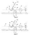
- the device further comprises a single front reflection mirror 19, integral with the flap 18 and supported by the internal wall thereof, intended to reflect an optical beam for reading from the front face of a game ticket internal to the device.
- the mirror 19 When the shutter 18 is closed, the mirror 19 is arranged below the recess of the shutter 18 and it extends through the optical axis 9, at the front of the window 13, in a plane slightly tilted forward on the optical axis 9 relative to the image plane P im .
- the sensor CCD 4 can read information on both sides, back and front, of a game ticket inserted in the device, as well as on the back of a ticket external to the device.
- a light-emitting diode (LED) bar 22 for lighting a ticket play space is arranged at the rear of the window 13.
- a light concentrator 23, attached to the LED bar 22, is intended to narrow the cone formed by the light beams to increase the power of lighting, in the direction of the optical axis.
- An optical filter 24 is attached to the front of the optical module 6, on the input of it located in the vicinity of the entrance pupil 10, and intended to filter the light surrounding the device, allowing only the lengths to pass waves generally between 600 and 3000 nm (nanometers). Thanks to this, the device can read an external game ticket, with the shutter 18 open, without risk of disturbance due to ambient light.
- the device comprises a central control unit, to which all the elements of the device are connected and intended to control the operation, as well as a play button to control playback a game ticket external to the device.
- the game ticket 100 supports on its faces, rear 101 and front 102 respectively, an information zone Z 1 and an information zone Z 2 , each containing a bar code.
- a user After closing the reading window 17 by closing the shutter 18, a user introduces the ticket 100 into the device via the input 14. During from its introduction, the ticket 100 is taken between the gripping roller and and the support plate and detected by the presence detector which activates the CCD 4 sensor and controls the rotation drive of the roller gripping and training ticket 100.
- the ticket 100 is driven in downward movement, under the action of the rotary drive of the gripping roller and drive, in the receiving passage 16, from the inlet 14 to the outlet 15, passing through a reading position of the information zone Z 2 of the front face 102, by reflection on the mirror 19, then by a direct reading position of the information zone Z 1 of the rear face 101.
- the ticket 100 In the reading position of the information zone Z 2 , the ticket 100 is located above the optical axis 9 and its front face extends in the object plane P 2 .
- the information zone Z 2 extends perpendicular to the plane of FIGS. 1 and 2 and is illuminated by the light bar 22, by reflection on the mirror 19.
- the zone Z 2 emits an optical beam 103 for reading the code- bar from the front face 102 towards the front mirror 19 which reflects it towards the rear, parallel to the optical axis 9.
- the reading beam 103 passes through the glass 13, passing below the ticket 100, then the optical system 8, the window 12 and finally strikes the detection surface 5.
- the CCD sensor 4 reads the information from the zone Z 2 , using the received reading beam.
- the ticket 100 intercepts the optical reading beam from the front face.
- the ticket 100 In the reading position of the information zone Z 1 , the ticket 100 therefore intercepts the optical reading beam from the front face 102 and the rear face 101 extends in the object plane P 1 .
- the information zone Z 1 extends through the optical axis 9, perpendicular to the plane of FIGS. 1 and 2. It is illuminated by the light bar 22 and emits towards the rear, parallel to the optical axis 9, an optical beam 104 for reading the barcode of the rear face 101, which passes through the window 13, the filter 24, the optical system 8 and the window 12, and finally strikes the detection surface 5.
- the CCD sensor 4 reads the bar code of zone Z 1 , using the reading beam 104 received.
- the depth of field of the optical system 8 is at least equal to the difference between the path of the reading optical beam of the face back of ticket 100 and the optical path of the reading optical beam of the front face of the ticket 100. Thanks to this, the optical reading assembly 1 reads the rear 101 and front 102 barcodes with resolution sufficient.
- the ticket 100 After reading the information zone Z 1 , the ticket 100 continues to move downward, under the action of the rotational drive of the gripping and driving roller, and is ejected from the device by the outlet 15.
- the game ticket here comprises an information zone Z 3 , containing a bar code, carried by one of its faces.
- the user After having cleared the reading window 17 by opening the shutter 18, the user positions the ticket in front of the window 17, substantially vertically, in an object plane P 3 , orienting towards the rear the face supporting the area d information Z 3 , which will therefore be described subsequently as "rear face".
- This rear face is then located in an object plane P 3 , located at a distance from the image plane P im of between 205 and 225 mm along the optical axis 9, and the information zone Z 3 extends through the optical axis 9, perpendicular to the plane of Figures 1 and 2.
- the user presses the read button on the device in order to activate the CCD sensor 4.
- the information zone Z 3 lit by the light bar 22 , emits towards the rear an optical beam for reading the bar code which passes through the reading window 17, the window 13, the filter 24, the optical system 8 and the window 12, before coming to strike the detection surface 5.
- the CCD sensor 4 reads the bar code of the reading zone Z 3 , using the received reading beam.
- the depth of field of the optical system 8 is at less equal to the difference between the direct reading optical path of the face back of a game ticket internal to the device and the optical reading path direct from the back of a game ticket external to the device. Thanks to that, optical reader assembly 1 can read bar codes clearly carried the respective rear sides of an external game ticket and a ticket internal game play.
- the device would include, between a game ticket entry and exit, a generally vertical passage of receiving and guiding the game ticket, arranged to receive and guide the game ticket dragged downward, under the effect of its own weight, in other words by gravity, of the entry towards the exit.
- the reflection mirror 19 for reading the information on the front of a game ticket and the sensor 4 are arranged so that the reading beam 103 passes through the window 13 of receipt of the ticket by passing below the ticket.
- the device for reading the invention could be arranged to read any other type of information such as cross, handwritten information, etc.
- the processing system information read by the CCD sensor could be arranged to code the information read in grayscale or in color.
Landscapes
- Physics & Mathematics (AREA)
- Engineering & Computer Science (AREA)
- Electromagnetism (AREA)
- Artificial Intelligence (AREA)
- Toxicology (AREA)
- General Health & Medical Sciences (AREA)
- Health & Medical Sciences (AREA)
- Computer Vision & Pattern Recognition (AREA)
- General Physics & Mathematics (AREA)
- Theoretical Computer Science (AREA)
- Time Recorders, Dirve Recorders, Access Control (AREA)
- Management, Administration, Business Operations System, And Electronic Commerce (AREA)
- Credit Cards Or The Like (AREA)
- Devices For Checking Fares Or Tickets At Control Points (AREA)
- Image Input (AREA)
Abstract
Description
- la figure 1 représente une vue en coupe latérale du dispositif de lecture, sans capot de protection supérieur, selon la forme de réalisation particulière, en position ouverte;
- la figure 2 représente une vue en coupe latérale du dispositif de lecture de la figure 1, en position fermée;
- la figure 3 représente une vue en perpective du dispositif de la figure 1;
- la figure 4 représente une vue schématique du système optique de lecture du dispositif de la figure 1, lors de la lecture de la face avant d'un ticket de jeu interne au dispositif et
- la figure 5 représente une vue schématique du système optique de lecture du dispositif de la figure 1, lors de la lecture de la face arrière d'un ticket de jeu interne au dispositif.
| Distance focale | 24,6 mm±0,7 mm |
| Ouverture N (ou nombre-F) | 17,8 ± 6% |
| Grossissement | - 0,1834 |
| Longueur d'ondes | 660 nm ± 30 nm |
| Profondeur de champ (P.C.) | ± 35 mm autour d'un plan situé à 190 mm du plan image Pim, le long de l'axe optique |
| Taille objet | 105 mm (pour P.C.= 155 mm) 132,1 mm (pour P.C. = 190 mm) 159,2 mm (pour P.C. = 225 mm) |
| FTM (Fonction de Transfert de Modulation) | > 40% (2 cycles / mm sur le plan objet) ( > 40% (10,9 cycles / mm sur le plan image)) |
| Distorsion | > |0,2%| |
| Pupille de sortie | à 24,8 mm du plan image |
| vitres | côté objet (vitre 13): épaisseur = 2 mm; n = 1,51 côté image (vitre 12): épaisseur = 0,8 mm; n = 1,51 |
| Taille de l'objectif | 16 mm (diamètre) X 13 mm (longueur) |
Claims (11)
- Dispositif de lecture optique d'informations portées par les deux faces, arrière (101) et avant (102), d'un support d'informations (100), comprenant des moyens (14, 16, 13) de réception du support (100) dans le dispositif, des moyens de lecture optique (4), des moyens de réflexion (19) sur l'axe (9) des moyens de lecture (4) et des moyens agencés pour que le support d'informations (100) et les moyens de lecture optique (4) soient entraínés en déplacement relatif pour lire les informations de la face avant (102) du support (100), par réflexion sur lesdits moyens de réflexion (19), et pour lire directement les informations de la face arrière (101) du support (100), le support (100) interceptant le faisceau optique (103) de lecture de la face avant (102) du support (100), caractérisé par le fait que les moyens de réception (13) du support (100) sont agencés pour que le support (100) soit incliné sur l'axe (9) des moyens de lecture (4) et lesdits moyens de réflexion comprennent un unique miroir (19).
- Dispositif selon la revendication 1, dans lequel il est prévu un mécanisme d'entraínement en déplacement relatif du support d'informations (100) et des moyens de lecture optique (1).
- Dispositif selon la revendication 1, dans lequel il est prévu, entre une entrée supérieure et une sortie inférieure de support d'informations (100), un passage de réception du support d'informations agencé pour que ledit support se déplace de l'entrée vers la sortie sous l'effet de son propre poids.
- Dispositif selon l'une des revendications 1 à 3, dans lequel les moyens de lecture optique (1) comprennent un capteur optique (4) associé à un système optique (8) à grande profondeur de champ.
- Dispositif selon la revendication 4, dans lequel la profondeur de champ du système optique (8) est au moins égale, pour une résolution optique suffisante pour lire les informations, à la différence entre les trajets des faisceaux optiques de lecture de la face arrière (101) et de la face avant (102) du support (100), respectivement.
- Dispositif selon l'une des revendications 1 à 5, dans lequel le dispositif comporte une fenêtre (17) de lecture d'un support d'informations (120) externe au dispositif.
- Dispositif selon la revendication 6, dans lequel il est prévu un volet (18) d'obturation de la fenêtre de lecture (17), mobile entre une position ouverte de lecture d'un support d'informations (120) externe au dispositif et une position fermée de lecture d'un support d'informations (100) interne au dispositif.
- Dispositif selon la revendication 7, dans lequel le miroir de réflexion (19) est solidaire du volet d'obturation (18).
- Dispositif selon l'une des revendications 1 à 8, dans lequel les moyens de lecture optique (1) comprennent un capteur CCD (4).
- Dispositif selon l'une des revendications 1 à 9, dans lequel il est prévu des moyens d'éclairage (22) associés à des moyens (23) de concentration de l'énergie lumineuse.
- Dispositif selon l'une des revendications 1 à 10, dans lequel il est prévu un filtre optique (24) pour filtrer la lumière environnant le dispositif.
Applications Claiming Priority (2)
| Application Number | Priority Date | Filing Date | Title |
|---|---|---|---|
| FR9901841A FR2789782B1 (fr) | 1999-02-16 | 1999-02-16 | Dispositif de lecture optique d'informations portees par un support tel qu'un ticket de jeu |
| FR9901841 | 1999-02-16 |
Publications (1)
| Publication Number | Publication Date |
|---|---|
| EP1030261A1 true EP1030261A1 (fr) | 2000-08-23 |
Family
ID=9542060
Family Applications (1)
| Application Number | Title | Priority Date | Filing Date |
|---|---|---|---|
| EP00400422A Withdrawn EP1030261A1 (fr) | 1999-02-16 | 2000-02-15 | Dispositif de lecture optique d'information portées par un support tel qu'un ticket de jeu |
Country Status (4)
| Country | Link |
|---|---|
| EP (1) | EP1030261A1 (fr) |
| CN (1) | CN1163839C (fr) |
| FR (1) | FR2789782B1 (fr) |
| TW (1) | TW480453B (fr) |
Families Citing this family (1)
| Publication number | Priority date | Publication date | Assignee | Title |
|---|---|---|---|---|
| US7281658B2 (en) * | 2005-01-31 | 2007-10-16 | Symbol Technologies, Inc. | Scan module |
Citations (6)
| Publication number | Priority date | Publication date | Assignee | Title |
|---|---|---|---|---|
| US3894216A (en) * | 1973-07-27 | 1975-07-08 | Compucorp | Illumination and sensor arrangement for card reader |
| JPS6315566A (ja) * | 1986-07-08 | 1988-01-22 | Canon Inc | 画像読取装置 |
| US5053612A (en) * | 1990-03-28 | 1991-10-01 | Tech-S, Inc. | Barcode badge and ticket reader employing beam splitting |
| US5541419A (en) * | 1994-03-21 | 1996-07-30 | Intermec Corporation | Symbology reader wth reduced specular reflection |
| DE19638128A1 (de) * | 1996-09-18 | 1997-12-04 | Siemens Ag | Einrichtung zum Umsetzen von auf Aufzeichnungsträgern abgebildeten Abbildungen in Bilddaten und zum Ausgeben dieser Bilddaten |
| WO1998010366A1 (fr) * | 1996-09-05 | 1998-03-12 | Electro Scientific Industries, Inc. | Systeme optique de visualisation permettant de visualiser simultanement des codes places sur les surfaces superieure et inferieure d'un substrat |
-
1999
- 1999-02-16 FR FR9901841A patent/FR2789782B1/fr not_active Expired - Fee Related
-
2000
- 2000-02-15 EP EP00400422A patent/EP1030261A1/fr not_active Withdrawn
- 2000-02-16 CN CNB001026178A patent/CN1163839C/zh not_active Expired - Fee Related
- 2000-03-10 TW TW089102226A patent/TW480453B/zh not_active IP Right Cessation
Patent Citations (6)
| Publication number | Priority date | Publication date | Assignee | Title |
|---|---|---|---|---|
| US3894216A (en) * | 1973-07-27 | 1975-07-08 | Compucorp | Illumination and sensor arrangement for card reader |
| JPS6315566A (ja) * | 1986-07-08 | 1988-01-22 | Canon Inc | 画像読取装置 |
| US5053612A (en) * | 1990-03-28 | 1991-10-01 | Tech-S, Inc. | Barcode badge and ticket reader employing beam splitting |
| US5541419A (en) * | 1994-03-21 | 1996-07-30 | Intermec Corporation | Symbology reader wth reduced specular reflection |
| WO1998010366A1 (fr) * | 1996-09-05 | 1998-03-12 | Electro Scientific Industries, Inc. | Systeme optique de visualisation permettant de visualiser simultanement des codes places sur les surfaces superieure et inferieure d'un substrat |
| DE19638128A1 (de) * | 1996-09-18 | 1997-12-04 | Siemens Ag | Einrichtung zum Umsetzen von auf Aufzeichnungsträgern abgebildeten Abbildungen in Bilddaten und zum Ausgeben dieser Bilddaten |
Non-Patent Citations (1)
| Title |
|---|
| PATENT ABSTRACTS OF JAPAN vol. 012, no. 221 (E - 625) 23 June 1988 (1988-06-23) * |
Also Published As
| Publication number | Publication date |
|---|---|
| FR2789782A1 (fr) | 2000-08-18 |
| CN1266242A (zh) | 2000-09-13 |
| TW480453B (en) | 2002-03-21 |
| FR2789782B1 (fr) | 2007-12-07 |
| CN1163839C (zh) | 2004-08-25 |
Similar Documents
| Publication | Publication Date | Title |
|---|---|---|
| EP0978084A1 (fr) | Dispositif optoelectronique d'acquisition d'images, notamment de codes a barres | |
| FR2909505A1 (fr) | Camera modulaire. | |
| FR2558971A1 (fr) | Appareil de formation d'images d'empreintes digitales | |
| CH689603A5 (fr) | Détecteur de fumée. | |
| FR2709837A1 (fr) | Appareil de mesure optique de distance, et lentille et élément photorécepteur pour sa mise en oeuvre. | |
| EP0015170A1 (fr) | Dispositif spectrophotométrique pour mesure à distance | |
| EP1421364A1 (fr) | Dispositif pour l'analyse d'un echantillon notamment par cytometrie de flux | |
| CA1101983A (fr) | Dispositif d'analyse d'un document, en particulier pour emetteur de fac-simile | |
| EP0674775B1 (fr) | Telescope pour imagerie infrarouge ou visible | |
| EP0577461B1 (fr) | Lecteur omnidirectionnel de vignettes de code à barre, à zone de lecture agrandie | |
| EP0588695B1 (fr) | Dispositif perfectionné d'analyse de supports d'informations | |
| EP1030261A1 (fr) | Dispositif de lecture optique d'information portées par un support tel qu'un ticket de jeu | |
| EP0742171A2 (fr) | Détecteur photoélectrique pour un dispositif de contrÔle du registre dans une machine d'impression rotative | |
| EP0557193A1 (fr) | Dispositif pour le tirage aléatoire de figures planes | |
| FR2570489A1 (fr) | Procede et dispositif pour le controle des volumes de verre apres decoupe | |
| FR2551890A1 (fr) | Dispositif d'analyse de champ spatial pour la localisation angulaire d'objets rayonnants | |
| FR3025913A1 (fr) | Dispositif de lecture de codes-barres et machine pour l'analyse automatise d'un echantillon comprenant un tel dispositif | |
| FR2714751A1 (fr) | Dispositif anti-encrassement pour écran de transmission de lumière entre un support d'informations éclairé par une source lumineuse et des éléments de lecture. | |
| EP1983495A1 (fr) | Détecteur de fumée avec dispositif adjacent à un réflecteur pour sélectionner un faisceau lumineux | |
| WO2013007916A1 (fr) | Scanner ultra compact a lecture fixe | |
| MC1809A1 (fr) | Detecteur photo-sensible | |
| EP1077641A1 (fr) | Capteur optique d'empreinte digitale compact | |
| FR2672144A1 (fr) | Dispositif pour le controle de vehicules a l'endroit d'un poste de controle ou similaire. | |
| EP3563288B1 (fr) | Lecteur de code à barres | |
| FR2661367A1 (fr) | Machine a imprimer, en particulier machine a empreindre a chaud, et dispositif d'exploration destine a lui etre associe. |
Legal Events
| Date | Code | Title | Description |
|---|---|---|---|
| PUAI | Public reference made under article 153(3) epc to a published international application that has entered the european phase |
Free format text: ORIGINAL CODE: 0009012 |
|
| AK | Designated contracting states |
Kind code of ref document: A1 Designated state(s): DE ES GB IT |
|
| AX | Request for extension of the european patent |
Free format text: AL;LT;LV;MK;RO;SI |
|
| 17P | Request for examination filed |
Effective date: 20010208 |
|
| AKX | Designation fees paid |
Free format text: BE DE ES GB IT |
|
| RBV | Designated contracting states (corrected) |
Designated state(s): DE ES GB IT |
|
| RAP1 | Party data changed (applicant data changed or rights of an application transferred) |
Owner name: SAGEM DEFENSE SECURITE |
|
| RAP1 | Party data changed (applicant data changed or rights of an application transferred) |
Owner name: SAGEM SECURITE |
|
| STAA | Information on the status of an ep patent application or granted ep patent |
Free format text: STATUS: THE APPLICATION IS DEEMED TO BE WITHDRAWN |
|
| 18D | Application deemed to be withdrawn |
Effective date: 20100901 |