EP1029518A2 - Prothèse aortique et méthode d'utilisation pour le traitement d'un anévrisme aortique abdominal - Google Patents
Prothèse aortique et méthode d'utilisation pour le traitement d'un anévrisme aortique abdominal Download PDFInfo
- Publication number
- EP1029518A2 EP1029518A2 EP00890039A EP00890039A EP1029518A2 EP 1029518 A2 EP1029518 A2 EP 1029518A2 EP 00890039 A EP00890039 A EP 00890039A EP 00890039 A EP00890039 A EP 00890039A EP 1029518 A2 EP1029518 A2 EP 1029518A2
- Authority
- EP
- European Patent Office
- Prior art keywords
- graft
- aortic
- aorta
- leg
- main portion
- Prior art date
- Legal status (The legal status is an assumption and is not a legal conclusion. Google has not performed a legal analysis and makes no representation as to the accuracy of the status listed.)
- Granted
Links
Images


Classifications
-
- A—HUMAN NECESSITIES
- A61—MEDICAL OR VETERINARY SCIENCE; HYGIENE
- A61F—FILTERS IMPLANTABLE INTO BLOOD VESSELS; PROSTHESES; DEVICES PROVIDING PATENCY TO, OR PREVENTING COLLAPSING OF, TUBULAR STRUCTURES OF THE BODY, e.g. STENTS; ORTHOPAEDIC, NURSING OR CONTRACEPTIVE DEVICES; FOMENTATION; TREATMENT OR PROTECTION OF EYES OR EARS; BANDAGES, DRESSINGS OR ABSORBENT PADS; FIRST-AID KITS
- A61F2/00—Filters implantable into blood vessels; Prostheses, i.e. artificial substitutes or replacements for parts of the body; Appliances for connecting them with the body; Devices providing patency to, or preventing collapsing of, tubular structures of the body, e.g. stents
- A61F2/02—Prostheses implantable into the body
- A61F2/04—Hollow or tubular parts of organs, e.g. bladders, tracheae, bronchi or bile ducts
- A61F2/06—Blood vessels
- A61F2/07—Stent-grafts
-
- A—HUMAN NECESSITIES
- A61—MEDICAL OR VETERINARY SCIENCE; HYGIENE
- A61F—FILTERS IMPLANTABLE INTO BLOOD VESSELS; PROSTHESES; DEVICES PROVIDING PATENCY TO, OR PREVENTING COLLAPSING OF, TUBULAR STRUCTURES OF THE BODY, e.g. STENTS; ORTHOPAEDIC, NURSING OR CONTRACEPTIVE DEVICES; FOMENTATION; TREATMENT OR PROTECTION OF EYES OR EARS; BANDAGES, DRESSINGS OR ABSORBENT PADS; FIRST-AID KITS
- A61F2/00—Filters implantable into blood vessels; Prostheses, i.e. artificial substitutes or replacements for parts of the body; Appliances for connecting them with the body; Devices providing patency to, or preventing collapsing of, tubular structures of the body, e.g. stents
- A61F2/82—Devices providing patency to, or preventing collapsing of, tubular structures of the body, e.g. stents
- A61F2/86—Stents in a form characterised by the wire-like elements; Stents in the form characterised by a net-like or mesh-like structure
- A61F2/89—Stents in a form characterised by the wire-like elements; Stents in the form characterised by a net-like or mesh-like structure the wire-like elements comprising two or more adjacent rings flexibly connected by separate members
-
- A—HUMAN NECESSITIES
- A61—MEDICAL OR VETERINARY SCIENCE; HYGIENE
- A61F—FILTERS IMPLANTABLE INTO BLOOD VESSELS; PROSTHESES; DEVICES PROVIDING PATENCY TO, OR PREVENTING COLLAPSING OF, TUBULAR STRUCTURES OF THE BODY, e.g. STENTS; ORTHOPAEDIC, NURSING OR CONTRACEPTIVE DEVICES; FOMENTATION; TREATMENT OR PROTECTION OF EYES OR EARS; BANDAGES, DRESSINGS OR ABSORBENT PADS; FIRST-AID KITS
- A61F2/00—Filters implantable into blood vessels; Prostheses, i.e. artificial substitutes or replacements for parts of the body; Appliances for connecting them with the body; Devices providing patency to, or preventing collapsing of, tubular structures of the body, e.g. stents
- A61F2/82—Devices providing patency to, or preventing collapsing of, tubular structures of the body, e.g. stents
- A61F2/86—Stents in a form characterised by the wire-like elements; Stents in the form characterised by a net-like or mesh-like structure
- A61F2/90—Stents in a form characterised by the wire-like elements; Stents in the form characterised by a net-like or mesh-like structure characterised by a net-like or mesh-like structure
-
- A—HUMAN NECESSITIES
- A61—MEDICAL OR VETERINARY SCIENCE; HYGIENE
- A61F—FILTERS IMPLANTABLE INTO BLOOD VESSELS; PROSTHESES; DEVICES PROVIDING PATENCY TO, OR PREVENTING COLLAPSING OF, TUBULAR STRUCTURES OF THE BODY, e.g. STENTS; ORTHOPAEDIC, NURSING OR CONTRACEPTIVE DEVICES; FOMENTATION; TREATMENT OR PROTECTION OF EYES OR EARS; BANDAGES, DRESSINGS OR ABSORBENT PADS; FIRST-AID KITS
- A61F2/00—Filters implantable into blood vessels; Prostheses, i.e. artificial substitutes or replacements for parts of the body; Appliances for connecting them with the body; Devices providing patency to, or preventing collapsing of, tubular structures of the body, e.g. stents
- A61F2/02—Prostheses implantable into the body
- A61F2/04—Hollow or tubular parts of organs, e.g. bladders, tracheae, bronchi or bile ducts
- A61F2/06—Blood vessels
- A61F2002/065—Y-shaped blood vessels
- A61F2002/067—Y-shaped blood vessels modular
-
- A—HUMAN NECESSITIES
- A61—MEDICAL OR VETERINARY SCIENCE; HYGIENE
- A61F—FILTERS IMPLANTABLE INTO BLOOD VESSELS; PROSTHESES; DEVICES PROVIDING PATENCY TO, OR PREVENTING COLLAPSING OF, TUBULAR STRUCTURES OF THE BODY, e.g. STENTS; ORTHOPAEDIC, NURSING OR CONTRACEPTIVE DEVICES; FOMENTATION; TREATMENT OR PROTECTION OF EYES OR EARS; BANDAGES, DRESSINGS OR ABSORBENT PADS; FIRST-AID KITS
- A61F2/00—Filters implantable into blood vessels; Prostheses, i.e. artificial substitutes or replacements for parts of the body; Appliances for connecting them with the body; Devices providing patency to, or preventing collapsing of, tubular structures of the body, e.g. stents
- A61F2/02—Prostheses implantable into the body
- A61F2/04—Hollow or tubular parts of organs, e.g. bladders, tracheae, bronchi or bile ducts
- A61F2/06—Blood vessels
- A61F2/07—Stent-grafts
- A61F2002/075—Stent-grafts the stent being loosely attached to the graft material, e.g. by stitching
-
- A—HUMAN NECESSITIES
- A61—MEDICAL OR VETERINARY SCIENCE; HYGIENE
- A61F—FILTERS IMPLANTABLE INTO BLOOD VESSELS; PROSTHESES; DEVICES PROVIDING PATENCY TO, OR PREVENTING COLLAPSING OF, TUBULAR STRUCTURES OF THE BODY, e.g. STENTS; ORTHOPAEDIC, NURSING OR CONTRACEPTIVE DEVICES; FOMENTATION; TREATMENT OR PROTECTION OF EYES OR EARS; BANDAGES, DRESSINGS OR ABSORBENT PADS; FIRST-AID KITS
- A61F2/00—Filters implantable into blood vessels; Prostheses, i.e. artificial substitutes or replacements for parts of the body; Appliances for connecting them with the body; Devices providing patency to, or preventing collapsing of, tubular structures of the body, e.g. stents
- A61F2/95—Instruments specially adapted for placement or removal of stents or stent-grafts
- A61F2/958—Inflatable balloons for placing stents or stent-grafts
- A61F2002/9583—Means for holding the stent on the balloon, e.g. using protrusions, adhesives or an outer sleeve
Definitions
- the present invention relates to an aortic graft and the use thereof, for treating abdominal aneurysms, and particularly relates to a graft and use thereof for intraluminal repairing of aortic aneurysms by positioning the graft inside the aneurysm without the drawbacks of conventional monoiliac or bifurcated aorto iliac grafts, such drawbacks relating to the rotation and misplacement of the graft during the insertion, positioning and installation of the graft inside the aorta.
- the aorta is the main trunk of the arterial system, arising from the heart and extending down through the thorax and through the abdomen to divide into two iliac arteries.
- An abdominal aortic aneurysm is an abnormal dilation of the aortic wall as the aorta passes through the abdomen.
- the aneurysm must be treated to prevent the rupturing thereof. If left untreated, the aneurysm will eventually cause rupture of the sac with fatal hemorrhaging consequences in a very short time. This leads to the death of the individual suffering the aneurysm and, today, the mortality resulting form this abnormality is so very high that it is causing the physicians to seek for improved new techniques to overcome this problem. While surgery has been the most classical way to approach this problem, the surgical repair of the aortic wall is associated, however, to a high risk, particularly for old patients.
- US Patent N° 4,562,596, to Elliot Kornberg et al. discloses an aortic bifurcated graft that is specifically designed for intraluminal insertion and comprising a one-piece generally cylindrical hollow sleeve, that has an upper end to be attached to an upper proximal neck of the aorta, upstream the aneurysm, and a minor and major axis defining two lower legs to be inserted each into a respective iliac artery, downstream of the aneurysm, thus forming a continuous fluid path within the aorta, excluding the affected aortic wall, namely the aneurysm, from the blood flow.
- US Patent N° 4,922,905 relates to a catheter and discloses a tubular endoprosthesis device having a wall structure comprised of a tube-like, knitted open fabric of loosely interlocked loops of metallic filament material, said tube-like fabric being radially inwardly deformed relative to its as-knit form and is capable of progressive permanent deformation with attendant radial expansion by means of the catheter to attach the endoprosthesis inside a blood vessel to be repaired.
- WO 83/03752 to Wallsten, Hans Ivar discloses a prosthesis comprising a one-piece expandable tubular body to be inserted into a vascular vessel.
- WO 90/15582 to Trout, Hugh discloses an aortic graft comprising a substantially cylindrical graft material with attachment means which comprise a plurality of post and hook assemblies to provide firm attachment of the aortic graft against the aortic wall.
- graft structures Although many graft structures have been developed, all of them have been improved in connection to new materials, new attachment means, stents and/or new devices for placing and installing the graft inside the vessel.
- the location and correct placing of the graft inside a blood vessel, particularly a graft designed for repairing aortic aneurysms are not an easy task as long as the aorta is the largest vessel with a shape that requires that special consideration is made not only of the dilated wall but also of such portions of the wall in good conditions available for firmly attaching the graft in the aorta.
- One obstacle that is found during election of the graft for a given patient is that the length of the aorta is not the same for all patients and, even for the same patient the aorta has an inner diameter at the upper or proximal aortic neck and the iliac arteries have a smaller different diameter. Furthermore, the ratio between the aortic diameter and the iliac diameters are not always the same, therefore it is today necessary to have large number of grafts combining a large number of upper diameters, for the aortic neck, and lower diameters, for the iliac arteries.
- the problem of the different sizes and shapes of the aortas is also an important issue at the time of placing the upper end of the graft in the correct site at the aortic proximal neck for obtaining a firm attachment of the graft on the neck and for sealing the graft against the neck of the aorta to avoid any blood flowing by the graft to leak out of the graft into the excluded aneurysm. That is, the blood flow must only circulate restricted to the interior of the graft without any leaking being produced at the attachment site.
- the graft includes, at each end thereof, an anchoring means, called stents, each stent being firmly attached to each graft end with a portion of each stent protruding beyond the associated end, such protruding portion being designed to be anchored against the aortic or iliac walls. Therefore, if the graft is not long enough, it may be that the stent remains firmly attached to the aortic proximal neck without the end of the graft material being correctly placed and sealed against the aortic neck wall. In this situation, the graft will be firmly retained against the aorta wall but the graft material will not be sealed against the aortic neck at the attachment site.
- stents an anchoring means
- the diameter of the aortic neck must be carefully taken into account at the time of selecting the graft. If the graft is of a diameter insufficient to match the aortic neck diameter, there will be a blood leak trough a gap formed between the graft and the aortic wall. If the graft diameter is in excess, the upper edge of the graft will be folded, forming little gaps against the aortic wall, with the same leakage problems above explained.
- grafts made of resilient fabric with stents made of resilient self-expanding material capable of self-expanding to a maximum diameter, or rigid stents made of a material construction that may be deformed by an expandable balloon and keep a final deformed diameter.
- resilient stents are not recommended because the exceeding diameter thereof causes the aortic wall to be permanently subject to an expanding force affecting the aortic wall integrity.
- rigid stents although recommendable for the patient's safety, involves some installation problems as below explained.
- the graft is loaded in a multiple folded condition inside a tubular inserting or positioning device, also called introducer or sheath, a catheter for example, to carry the graft to the site of installation and to deploy the graft by radially expanding the same by any known technique, by an expandable balloon for example.
- a tubular inserting or positioning device also called introducer or sheath, a catheter for example
- the graft is provided at respective upper and lower ends thereof with anchoring means, as explained above, generally comprised of metal stents capable of firmly attaching the graft against the corresponding vessel wall when the stent is in the expanded condition.
- the upper end of the graft undergoes a rotary movement relative to the lower end of the graft.
- the same effect may occur in connection to the lower ends relative to the upper end of the graft.
- the rotation of the graft ends may be produced by the inflation of the balloon which is made of an inelastic material that is multiply folded in the positioning device and, upon inflation, it rotates during deployment. This rotation is transferred to the graft.
- the rotation induced on the graft may be also produced by the movements of the introducer into the vessel during the deployment and installation of the graft. This twisting effect appears in all grafts, either monoiliac grafts made of a cylindrical material or bi-iliac grafts, that is the bifurcated grafts.
- the conventional grafts are made of a fabric material, either of elastic knitted material or inelastic woven material.
- the elastic grafts may accommodate better the several ratios between the different diameters of the aortic neck and the iliac arteries, these grafts are dramatically affected by the problem related to the length of the graft and the twisting effect above disclosed.
- the grafts made of inelastic woven material are affected by all of the above mentioned drawbacks of the conventional aortic grafts.
- this bifurcated graft is attached to the upper neck of the aorta and the lower end of the longest limb is attached inside the iliac artery through which the aorta has been acceded, the graft frequently results twisted along the upper trunk portion of the one-piece graft and the longest limb.
- the rotation of the trunk portion may have left the free short limb in a position diametrically opposite to the iliac artery that is free to receive said shorter limb.
- the longest limb, already attached inside the corresponding artery is interfering the path between the shorter limb and the free artery, thus blocking the path and preventing the shorter limb from being directed to and inserted into the corresponding free iliac artery. Therefore, although the shorter limb may have been not affected by the twisting effect, it is directed to a position that makes impossible to introduce the same into the artery.
- the nitinol wire although flexible in a cold state, behaves like a steel wire under the temperature inside a patient's body.
- Goicochea also proposes a method to install this graft consisting in placing a first bifurcated part and then enter this part by lower ends of same to introduce additional leg grafts and connect the same to lower openings in the bifurcated part.
- the risk of puncturing the aorta wall with the guide wire and introducer during this operation is enormous and the task of connecting the several parts inside the aorta is extremely difficult because the bifurcated part is semirigid and may adopt any aleatory position that causes the openings of same difficult to be reached.
- U.S. Patents N° 5,628,788 to Pinchuk et al; 5,632,772 to Alcime et al. and 5,639,278 to Dereume et al. disclose endoluminal grafts which are both expandable and supportive and are comprised of a supportive stent made of resilient wire elements and cover or liner made of a porous material over or inside the supportive wire structure.
- the same above explained problems are found in these grafts when trying to fold the same in an introducer, when passing the introducer through tortuous or restricted blood vessels and when fixing the stent to the available aorta wall.
- the graft can not be accommodated to this configuration, the forces exerted by the aorta to recover its initial position is transferred directly to the graft causing the same to alter its initial connection in the aortic neck.
- the same alterations occur in the graft legs connected to the main graft portion and the iliac arteries.
- the aortic neck is not always horizontal and it can be inclined as to the vertical axis of a patient's body. Under these circumstances a wire-made graft like the ones disclosed above can not be accommodated to this inclination.
- a similar problem is faced when the inner wall of the aortic neck is not entirely circular but has calciferous formations that make the neck inner wall irregular.
- this irregular perimeter can not be "copied” by a wire made graft, thus leaving portions of the aortic wall without being sealed therefore resulting in leaking of the blood flow. If, to overcome any of these problems relate to irregularities of the aortic neck, the graft is placed in a higher position, upwardly beyond the renal arteries, the flow through these arteries is blocked by the graft supportive construction formed by a dense wire mesh.
- connection between the parts conforming the graft is somewhat difficult to be achieved in a safety manner as long as the compliance and elasticity of the connecting materials cause the connection to be easily released if not firmly performed.
- this connection requires that barbs, hooks, clips, etc. be used to firmly fix the involved parts without the risk of detaching under the effect of the blood flow and other involved forces.
- This problem is not found in grafts made of no-compliant or inelastic fabrics because any conventional expandable stent used to make the connection will be expanded against the maximum diameter of the connecting parts exerting an important retaining radial force.
- aortic bifurcated graft capable of adapting to all of the size and shape characteristics of most of the aortas. It would also be necessary to find a new aortic graft capable of being installed without undergoing the above mentioned twisting effect and misplacing.
- the new graft is also capable of accommodating to any varying ratio between the diameters of an aortic neck and the iliac artery, the graft being also adapted to different aorta lengths and sizes, thus diminishing and even avoiding the risks of misplacing the graft inside the aorta.
- the use of the graft comprises inserting a guide wire in a blood vessel at a site remote to the site of an aorta affected by the aneurysm and moving the guide wire to make it enter the aneurysm by the aortic upper neck, inserting the graft main portion over the guide wire by means of a positioning device entering the aneurysm by an iliac artery, the positioning device including at least one expandable balloon, with the graft main portion being maintained in a compressed condition inside the positioning device with least the upper end of the graft main portion located over the balloon, positioning the graft inside the aorta at the site of the aneurysm and deploying the graft main portion by inflating the balloon, whereby the upper end of the graft main portion is securely attached to the proximal upper aortic neck, downwardly removing the positioning device, permitting the lower end of the graft main portion to freely rotate relative to the upper end of the graft main portion to unfold
- the graft comprising a three-portion tubular hollow flexible fabric material, the material being at least partially elastic or inelastic and the graft being capable of accommodating any varying ratio between the diameters of an aortic neck and the iliac arteries, the graft being also adapted to different aorta lengths and sizes, thus diminishing and even avoiding the risks of misplacing the graft inside the aorta.
- an aortic bifurcated graft for treatment of abdominal aortic aneurysms
- the graft comprising a tubular hollow material to be intraluminally inserted in the aorta, the aorta having an upper proximal aortic neck and a lower distal portion dividing into two iliac arteries, forming an iliac bifurcation
- the graft comprising a graft trunk portion having a generally cylindrical shape with an upper end to be securely attached to the aortic proximal neck, and a lower bifurcated short portion forming two lower side-by-side connecting ends, at least the upper end of the trunk portion being made of a flexible elastic, radially expandable, knitted fabric material, the connecting ends extending inside the aorta and being located upwardly and spaced apart from the iliac bifurcation, and a pair of graft iliac leg portions made of a flexible elastic, radially expand
- an aortic graft for treatment of abdominal aortic aneurysms, the graft comprising a tubular hollow material, either of the monoiliac type or the bi-iliac type, to be intraluminally inserted in the aorta, the aorta having an upper proximal aortic neck and a distal aortic lower portion forming an iliac bifurcation dividing into two iliac arteries, the graft comprising a graft main portion having an upper end to be securely attached to the aortic proximal neck, and a lower end hanging free at a position inside the aneurysm an above the iliac bifurcation, and a graft iliac leg portion having a generally elongated cylindrical shape with a lower end to be securely attached to one of the iliac arteries, and an upper end to be securely connected in fluid flow communication to the lower end of the graft main portion, both
- the term "flexible fabric” should be understood as any textile material or fabric of surgical grade, biocompatible, capable of being flexed in such a way that the tubular graft portions of the invention can follow the curved path of any vessel, even tortuous vessels, to accede to the aorta, and even capable of being accommodated into the aorta when the aorta has a multiply curved path, without any strangulation appearing in the tubular shapes of the graft portions, and without affecting the attachment at the respective ends of the portions and the aorta and iliac arteries.
- pending or "hanging” is used associated to some portions of the graft of the invention, it is attempted to mean that such portions, like the ends or the end portions of the main/trunk portions remain free and capable of freely moving, rotating, waving, floating, etc., in the blood flow, for example.
- These terms have been used to illustrate the capability of the main/trunk portion to accommodate to the aorta configuration and blood flow, and the terms were elected to make more illustrative this behavior of the graft in the position it is shown in the Figures, that is in a vertical position.
- the patient is horizontally positioned, whereby the main/trunk graft portion of the inventive embodiments will be freely moved by the blood flow in an horizontal pattern. Therefore, the terms pending and hanging, when used for the main/trunk portion once attached to the upper aortic neck, must be understood according to this explained concept.
- FIG. 1 an infra-renal aorta generally indicated by numeral reference 1, affected by an aneurysm consisting of an abnormal dilation 2 of the aortic wall.
- the aorta arises form the heart (not illustrated) and runs downwardly to divide into the iliac arteries 3, 4.
- an upper proximal aortic neck 5 and a lower distal aortic neck 6 are defined at upper and lower parts of the aneurysm.
- distal neck 6 is not formed, but the wall is also dilated, when the aneurysm extends to the bifurcation and also through the iliac arteries. If not treated, dilated wall, or aneurysm 2, becomes ruptured with ensuing fatal hemorrhaging in a very short time. Many attempts have been made to prevent and avoid the high mortality due to this abnormality, most of the attempts involving surgical techniques with associated high risk for the patient. In the recent years a less traumatic technique has been developed consisting of acceding the aorta intraluminally to insert and install inside the aorta a graft to exclude the aorta from the blood circulatory system.
- the graft When installing the graft in the aorta the graft may be firmly attached to those portions of the aortic wall in good conditions to provide a safe attachment, that is a firm anchoring and sealing coupling between the aortic graft and the aorta.
- three main graft types may be identify, namely the monoiliac aortic graft, shown in FIG. 1, comprising a cylindrical tubular one-piece or two-piece graft, the bi-iliac aortic grafts consisting of a bifurcated graft comprising an inverted Y-shape tubular graft, shown in FIG. 5, and the aorto-aortic graft (not shown) consisting of a sleeve with an upper stent to be attached to an upper neck of the aorta and a lower stent to be attached at a lower aortic neck.
- the aorto-aortic grafts not always can be used because it is frequent that the aneurysm has reached an extent that the lower aortic neck 6, excessively dilated, has disappeared and the lower end of the graft does not find a firm aortic wall to be fixed.
- bifurcated grafts As to the bifurcated grafts, the same are designed to have the trunk of the Y inserted and firmly attached to proximal neck 5 of the aorta while each branch or leg of the Y is inserted and installed inside a respective iliac artery 3, 4.
- the use of bifurcated grafts has shown many inconveniences as to the installation thereof, as it will be further disclosed below when referring to the bifurcated embodiment of the invention.
- the inventor of the present invention has developed a new graft, either monoiliac or bi-iliac graft that can be installed without being affected by the above and below remarked drawbacks.
- FIG. 1 A monoiliac aortic graft according to the prior art is shown in FIG. 1, the graft comprising a tubular material having an upper portion 8 with a larger diameter to be attached to the aortic proximal neck and a lower portion 9 having a smaller diameter to be installed within one 4 of the iliac arteries 3, 4.
- the fluid communication is thus defined between the aorta and iliac artery 4, then, the blood flow in iliac artery 3 is obtained by performing a connection between arteries 3 and 4 by a simple surgery downstream of the iliac bifurcation, the surgery being carried out in a zone of the human body where no vital organs are exposed to risks and iliac artery 3 is closed to avoid any blood back flow into the aneurysm through artery 3.
- the implanting of the monoiliac graft has shown to be simpler than the installation of the bi-iliac graft, the correct positioning of the graft is still hard to be obtained in the desired manner.
- the graft must be positioned inside the aorta by means of a tubular positioning device, such as an introducer or sheath.
- a tubular positioning device such as an introducer or sheath.
- the graft is multiply folded and compressed to fit snugly into the tubular positioning device, the positioning device is then introduced within the blood circulatory system of a patient to accede to the aorta with the graft in the device, with predetermined anchoring portions of the graft being folded around respective expandable balloons also located inside the positioning device.
- the graft is moved out of the positioning device and the expandable balloons are inflated to expand the graft.
- the graft is provided with anchoring means, preferably stents 10, 11, generally consisting of a metal expandable mesh capable of being expanded and keeping its expanded configuration after the balloon is deflated.
- anchoring means preferably stents 10, 11, generally consisting of a metal expandable mesh capable of being expanded and keeping its expanded configuration after the balloon is deflated.
- Each stent is located over a balloon, therefore, once the balloon is expanded the stent is radially outwardly deformed whereby it is firmly attached against the wall of the aorta, preferably at the proximal aortic neck, at any healthy portion of the aortic wall, or against a wall of the respective iliac artery.
- stent 10 is attached to aortic neck 5 while stent 11 is attached to iliac artery 4.
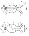
- a new aortic graft comprising a two-part graft illustrated in Figures 2-4.
- the inventive graft comprises a graft main portion 13 adapted to be attached to neck 5, and a graft leg portion 14 (Fig. 4) adapted to be attached to portion 13 and to one 4 of the iliac arteries 3, 4.
- Graft main portion 13 may be placed inside aorta 1 by any of the known techniques, by means of a introducer or tubular positioning device 15 running over a conventional guide wire 16.
- guide wire 16 is first inserted into the blood circulatory system and moved to reach the aorta by making an incision in a blood vessel at a site remote from the aorta.
- the incision is made in the groin of the patient to enter through a femoral artery, the incision, however, may be made in any other blood vessel as long as acceding to the aorta is ensured.
- a positioning device 15' carrying graft portion 13 and stent 17 firmly fixed at an upper end 18 of the graft portion is inserted into the incision and fed into the aorta.
- the stent and the graft snugly fit into the positioning device with the stent crimped over a balloon catheter (not shown) and the graft is wrapped around the stent and the balloon catheter, as it is conventionally used in a positioning device.
- the balloon is inflated to radially outwardly deform the stent to cause the same to be attached against the aortic wall at neck 5, with an upper edge of end 18 sealing against neck 5 to avoid any blood leakage.
- radio-opaque marks may be provided in upper end 18 and the balloon as it is well known in the art.
- Stent 17 may be, alternatively, of a resilient type with a tendency to expand to its relaxed condition at a fixed maximum diameter when the stent is released from its compressed condition as it is loaded inside the catheter, or, as it was above disclosed, the stent may be of the rigid type in which event the stent is made of a metallic mesh that is also loaded in a compressed condition inside the catheter but is radially outwardly deformed by the balloon into a permanent expanded condition.
- a rigid type stent is capable of retaining a permanent expanded deformation to firmly retain the graft against any forces from the blood flow and movements of the patient.
- Stent 17 is be made of any suitable biomedical grade metal.
- Graft main portion 13 has a generally cylindrical shape with upper end 18 to be securely attached to aortic proximal neck 5, and a tapered lower end portion forming and end 19 that is tapered by the diameter thereof reducing towards a lower edge 20 having the smallest diameter of the graft portion.
- tapered lower end 19 is a cone-shaped portion the diameter of which decreases towards edge 20.
- end 19 At either of the positions of end 19, this end will always be well unfolded, untwisted and oriented in such a way that it will be free of any flow restriction and will be aligned with the iliac artery through which the guide wire and positioning device have entered the aneurysm, in the drawing, artery 4. Even in any position rotated relative to the position shown in Figure 2, end 19 and edge 20 will remain in a convenient orientated position relative to any of the iliac arteries. This is very important to then connect the leg portion as it will be explained below.
- graft portion 13 when graft portion 13 is installed by deployment of the same from the positioning device, any rotation and/or twisting effect resulting from the outwardly deployment will disappear, even if the guide wire is not removed. Graft portion 13 may accommodate itself over the guide wire in order that the rotation thereof originated during installation will not twist the material because end 19 of the invention is free to rotate by accompanying the rotation upper end 18. When accompanying rotation, end 19 will result positioned in any of the rotated positions as explained above, without any twisted zones, thus differing from the case of the one-piece graft shown in Fig. 1.
- the second part of the graft, leg portion 14, is inserted into the aorta and connected to main portion 13.
- Positioning device 15, containing the loaded folded leg portion 14 and respective stents 21, 22, is conveyed over guide wire 16, so that device 15 is inserted into graft portion 13, particularly up to the position shown in Fig. 3.
- leg portion 14 is moved out of catheter 15 and deployed, by inflating, preferably simultaneously, respective balloons at the sites of stents 21, 22, into the configuration shown in Fig. 4, thus the leg portion being firmly attached to portion 13 and to iliac artery 4.
- Tubular positioning device is then removed as indicated by the arrow in Fig. 4.
- stents 21, 22 may be of a resilient type or may be of the rigid type as well as they are made of any suitable biomedical grade metal.
- self-expandable stents no balloons may be necessary to expand the above mentioned portions of the graft. Thus, the stents are just permitted to expand.
- Graft iliac leg portion 14 has a generally cylindrical shape with an upper end 23 to be securely connected in fluid flow communication to lower tapered portion or end 19 of the graft main portion, and a lower end 24 securely attached to one 4 of the iliac arteries.
- Graft leg portion 14 has a diameter smaller than the diameter of the graft main portion, the diameter of the graft main portion decreasing towards the lower end of the graft main portion to securely receive the upper end of the graft leg portion.
- End 23 being retained against end 19 by the expanded stent and end 23 of the leg portion is prevented from being dislodged because of the tapered configuration of end portion 19 forming a diameter interference in an overlapping between ends 19, 23. Any other kind of interference may be performed by a clamp or suture made at end 19, before installation, so as to restrict the diameter of end 19.
- the graft of the invention is installed by acceding to the aorta through an acceding blood vessel, preferably an iliac artery, wherein the graft is implanted by first placing main portion 13 as explained and then installing the secondary leg portion in the corresponding iliac artery 4 and connecting the main and leg graft portions to each other, whereby leg portion 14 is attached to the iliac artery and to main portion 13 once any rotation of the main portion, produced by the deployment and installation of the main portion has already occurred, whereby no rotation or twisting of the graft main portion is transferred to the graft leg portion.
- the installation comprises inserting guide wire 16 in a site remote to the site of the vessel affected by the aneurysm, preferably the aorta, and moving the guide wire to the site of the aneurysm; inserting the graft main portion over the guide wire by means of a positioning device, such as an introducer 15, including at least one expandable balloon, with the graft main portion being maintained in a compressed condition over the balloon; placing the graft in the site of the aneurysm and deploy the graft main portion by inflating the balloon, whereby upper end 18 of graft main portion 13 is securely attached to proximal aortic neck 5; removing the positioning or placing device and introducing the same or another new positioning device over the guide wire, the positioning device carrying the graft leg portion in a compressed condition until upper end 23 of the graft leg portion is inside lower end 19, passing edge 20, of the graft main portion, and deploying the graft leg portion by inflating the balloon of the catheter when the upper end of the graft
- Another advantage of the present invention as compared to the prior art is that the different ratios of the diameter of neck 5 and the diameter of iliac artery 3, 4, could be covered with only one main portion 13, or a few main portions, useful for any length of aorta, while the leg portion will be selected from a set of leg portions having different diameters and standard lengths.
- This combination of different main portions and different leg portions provides a wide spectrum of combinations that is also very helpful to cover a large number of lengths to correctly positioning of the graft along the entire distance between neck 5 and the necessary portion of the iliac artery, thus achieving a proper anchoring effect of the graft and a complete aneurysm exclusion.
- Another important aspect of the invention is related to the use of anchoring means of the resilient type, that is self-expanding stents.
- anchoring means of the resilient type that is self-expanding stents.
- the twisting effect to which wide reference has been made in connection to the use of rigid stents may also appear when using resilient stents because the graft is longitudinally placed within the tubular positioner or applicator and, when the graft is left to move out from the applicator the stents are released in a no simultaneous pattern.
- a bi-iliac bifurcated graft according to the prior art may be seen in FIG. 5.
- the known bi-iliac aortic graft consists of a bifurcated graft 25 comprising an inverted Y-shape tubular graft.
- the bifurcated graft is designed to have a trunk 26 of the Y inserted and firmly attached to proximal neck 5 of the aorta while each branch, limb or leg 27, 28 of the Y is inserted and installed inside a respective iliac artery 3, 4.
- the bifurcated grafts provide for a better design that should define a complete and fluid connection between the aorta and the iliac arteries
- the bifurcated grafts are affected by restrictions during the installation thereof as long as the connection of the leg portions to the trunk portion has been very complex and no reliable with the methods today available, particularly to position and deploy the graft into the aorta in a way that the graft were firmly and properly located in place.
- the trunk of the bifurcated graft could be placed in a conventional way, there were no reliable devices and techniques to position and attach the limbs of the Y in the correct place, within the respective iliac arteries.
- the graft must be positioned inside the aorta by means of a tubular positioning device, such as an introducer.
- a tubular positioning device such as an introducer.
- the graft is multiply folded and compressed to fit snugly into the tubular positioning device, the positioning device is then introduced within the blood circulatory system of a patient to accede to the aorta with the graft in the device, with predetermined anchoring portions of the graft being folded around at least one expandable balloon also located inside the positioning device.
- the graft is moved out of the positioning device and the expandable balloon or balloons is inflated to expand the graft.
- the bifurcated graft is provided with anchoring means, preferably stents 29, 30, 31 each generally consisting of a metal expandable mesh capable of being expanded and keeping its expanded configuration after the balloon is deflated.
- the stent is located over the balloon, therefore, once the balloon is expanded the stent is radially outwardly deformed whereby it is firmly attached against the wall of the aorta, at the proximal aortic neck, and against a wall of the respective iliac artery.
- stent 29 is attached to aortic neck 5 while stents 30 and 31 are attached to respective left and right iliac arteries 3 and 4.
- a new aortic graft comprising a three-part graft illustrated in Figures 6-13.
- the inventive graft comprises a graft trunk portion 33 adapted to be attached to neck 5, and two graft leg portions 34 and 35 ( Figures 8, 9, 11, 12) adapted to be attached to portion 33 and to the iliac arteries 3, 4.
- Graft trunk portion 33 may be placed inside aorta 1 by any of the known techniques, by means of an introducer or tubular trunk-positioning device 36 ( Figures 6, 12) running over a conventional guide wire 37.
- guide wire 37 is first inserted into the blood circulatory system and moved to reach the aorta by making an incision in a blood vessel at a site remote from the aorta.
- the incision is made in an artery in one of the arms of a patient.
- Guide wire 37 is then conveyed to enter by aortic neck 5 and towards one of the femoral arteries through which artery the guide wire is taken out of the patient's body through an incision in the groin of the patient so that a leading end of the guide wire is thus used to introduce a trunk-positioning device over the guide wire into the femoral artery.
- Trunk-positioning device 36 carrying graft portion 33 and an anchoring means, such as a stent 38 firmly fixed at an upper end 39 of the graft trunk portion, is inserted into the incision and fed into the aorta.
- the stent and the graft snugly fit into the trunk-positioning device and the stent is placed around a balloon (not shown) as it is conventionally used in an inserting or positioning device. Once the positioning device is in the correct position inside the aorta, particularly when stent 38 and end 39 are positioned as it is shown in Fig.
- the balloon is inflated to radially outwardly deform the stent to cause the same to be attached against the aortic wall at neck 5, with any upper edge of end 39 sealed against neck 5 to avoid any blood leakage.
- radio-opaque marks, or indicia may be provided in upper end 39 and the balloon as it is well known in the art.
- Stent 38 may be of a resilient type with a tendency to expand to its relaxed condition at a fixed maximum diameter when the stent is released from its compressed condition as it is loaded inside the introducer, or may be of the rigid type in which event the stent is made of a metallic mesh that is also loaded in a compressed condition inside the catheter but is radially outwardly deformed by the balloon into a permanent expanded condition.
- a rigid type stent is capable of retaining a permanent expanded deformation to firmly retain the graft against any forces from the blood flow and movements of the patient.
- Stent 38 is be made of any suitable biomedical grade metal.
- stent 38 is made of an open wire structure that, if upper aortic neck is dilated or irregular to bar a firm mounting of the stent, the stent may be placed beyond the renal arteries provided that the graft fabric do not close the arteries, and the wire stent will not block the blood flow through the renal arteries.
- Graft trunk portion 33 has a generally cylindrical shape with upper end 39 to be securely attached to aortic proximal neck 5, and a lower bifurcated short portion 40 forming two lower side-by-side connecting ends, a left connecting end 41 and a right connecting end 42.
- This configuration of the trunk portion assemblies a pair of pants, therefore connecting ends 41 and 42 may be also referred to along this description as pending legs of the pant.
- ends 41 and 42 may result positioned as it is shown in Fig. 7, that is the most favorable position with both ends almost aligned with iliac arteries 3, 4. Otherwise, ends 41, 42 may result positioned in any other position rotated about a longitudinal axis of the graft trunk, that is a less favorable position. According to the invention, however, whatever the position of ends 41 and 42 is resulted these ends will always be unfolded untwisted and well oriented for a correct further connection to leg portions 34, 35 to iliac arteries, as will be further explained in connection to Figures 9-13.
- ends 41, 42 will remain in a convenient orientated position relative to any of the iliac arteries. This is possible because ends 41, 42 are free moving from the trunk portion like in a pair of pants, thus permitting the ends to be moved in opposite directions without obstructing the blood flow, that is the ends or pending legs are not connected to each other like in some three-part grafts of the prior art.
- the two remaining parts of the inventive graft, leg portions 34 and 35 are inserted into the aorta and connected to main portion 33.
- the guide wire 37 Once guide wire 37 has been upwardly removed from connecting end 41 as shown in Figure 7 and trunk portion adopted its final position, the guide wire is inserted again by upper neck 39 and may pass through the best orientated of ends 41 or 42, in this case end 42 as shown in Fig. 8, to follow then through a femoral artery of the patient.
- a leg-positioning device 43 containing one loaded folded leg portion, for example right portion 16, and respective stents 44, 45, at respective upper and lower ends 46, 47, of the leg portion, is conveyed over guide wire 37, entering the patient's body by a femoral artery and entering the aorta by iliac artery 4 into end 42 until device 43 is at the position shown in Fig. 8.
- guide wire 37 is upwardly removed from positioning device 43 and replaced by a new guide wire 48, see Figure 9, wire 48 being inserted into device 43 by a rear end of device 43, to give support to the positioning device 43 inside the trunk portion.
- Guide wire 37 is upwardly removed just to be released from device 43 and is inserted through connecting end 41 to enter iliac artery 3 and another leg-positioning device 49 is inserted over guide wire 37 in like manner that device 43, but through an incision in the other groin of the patient.
- the positioning device 49 carries leg portion 35 and stents 50 and 51 respectively fixed at upper end 52 and lower end 53 of the left leg portion. Once in this position, devices 48, 49 are moved backwards as it is shown by the arrows in Fig 9, to then deploy leg portions 34, 35. Therefore, as illustrated in Figure 9, trunk portion 33 is installed in the aorta free of any twisting effect or rotation, with both leg portions 34, 35, in position to be simultaneously deployed, each one over guide wires 37, 48, respectively.
- stents 44, 45, 50, 51 are inflated to deploy stents 44, 45, 50, 51 to place the graft portions into the configuration shown in Fig. 10, thus the leg portions being firmly attached to trunk portion 33 and to iliac arteries 3, 4. Additional stents, not shown, may be used between stents 44, 45 and 50, 51, or only one long entire stent, as it is well known in the art, to avoid any possibility of graft leg kinking. Like stent 38, stents 44, 45, 50, 51 may be of a resilient type or may be of the rigid type as well as they are made of any suitable biomedical grade metal. If the resilient type is used, no balloons may be necessary.
- Figure 11 shows trunk portion 33 attached to aortic neck 5 and rotated closely 90° relative to the position shown in Figures 7-10, that is with connecting left and right ends 41, 42, respectively, aligned in a cross configuration relative to iliac arteries 3 and 4.
- trunk-positioning device 36 is introduced over the guide wire, through an iliac artery, the positioning device containing the trunk portion to be deployed inside the aorta. Trunk portion 33 is then deployed against aortic neck 5, undergoing a twisting effect like the one shown in Figure 6, with trunk-positioning device 36 being removed backwards and guide wire 37 upwardly removed from the trunk portion. Once the trunk portion is released from the guide wire, the trunk portion becomes relaxed and is free to rotate, whereby the twisting effect disappears from the trunk and the trunk remains freely moving and oriented as shown in Figure 11.
- Guide wire 37 is then reinserted into trunk portion 33 and passed to any of the connecting ends 41, 42, to be directed to any of the corresponding iliac arteries 3, 4.
- connecting ends 41 and 42 are not directly aligned with the corresponding iliac arteries 3 and 4
- guide wire 37 will pass either through connecting end 41 or through connecting end 42 to then enter either into artery 3 or artery 4.
- guide wire is illustrated as passing through end 42 and artery 4, the guide wire may have passed through end 42 and artery 3, or through end 41 and artery 4, without any twist, fold or restriction appearing on the graft.
- Leg-positioning device 43 is then inserted over guide wire 37, the leg-positioning device containing one loaded folded leg portion, for example right leg portion 34 and stents 44, 45, at upper and lower ends 46, 47 of the leg portion.
- Device 43 is inserted into the patient's body by a femoral artery and entering the aorta by iliac artery 4, until device 43 is at the position shown in Fig. 11.
- guide wire 37 is upwardly removed from positioning device 43 and simultaneously may be replaced by a new guide wire 48, see Figure 12, and the procedure is similar to the one disclosed in connection to Figures 6-10, that is wire 48 is inserted into device 43, at a rear end thereof, to give support to the leg-positioning device inside the trunk portion.
- Guide wire 37 once released from device 43, is inserted through connecting end 41 to enter iliac artery 3 and another leg-positioning device 49 is inserted over guide wire 37 in like manner that device 43, but through an incision in the other groin of the patient, see Figure 12.
- the leg-positioning devices carry leg portions 34, 35 with stents 44, 45, 50, 51 respectively fixed at the ends of the leg portions.
- trunk portion 33 is installed in the aorta free of any twisting effect or rotation, with both leg portions 34, 35, in position to be simultaneously deployed, each one over guide wires 48, 37, respectively.
- stents 44, 45, 50, 51 are inflated to deploy stents 44, 45, 50, 51 to place the graft portions into the configuration shown in Fig. 13, thus the leg portions being firmly attached to trunk portion 33 and to iliac arteries 3, 4. Additional stents, not shown, may be used between stents 44, 45 and 50, 51 (not shown), as it is well known in the art, to avoid any possibility of kinking.
- stents 44, 45, 50, 51 may be of a resilient type or may be of the rigid type as well as they are made of any suitable biomedical grade metal. If the resilient type is used, no balloons may be necessary.
- Graft iliac leg portions 34 and 35 are generally cylindrical elongated sleeves with an upper and lower ends duly designed to ensure a firm a sealed connection with connecting ends 41 and 42 of the trunk portion.
- Connecting ends 41 and 42 may have tapered configurations to form an interference with the upper end of the associated leg portion, or any other kind of diameter interference may be performed by a clamp or suture made at ends 41 and 42, before installation, so as to restrict the diameter of ends 41 and 42.
- One of the ends or pending legs 41, 42 may also be closed by suture, a clamp, etc. to convert the bi-iliac graft into a monoiliac graft. This reform may be also carried out according to the embodiment of the invention shown in FIG.
- Graft portions 33, 34, 35 may be manufactured from any suitable textile or fabric material, at least partially elastic or inelastic, either a woven or a knitted material.
- the inventive graft is preferably used in an aneurysm, wherein the aortic bifurcated graft 33, 34, 35 is intraluminally positioned and implanted by acceding to aorta 1 by a guide wire inserted through an aortic neck or an end neck of an aneurysm, the graft being inserted through a blood vessel, preferably femoral or iliac arteries 3, 4, wherein the bifurcated graft is implanted by first placing trunk portion 33 against upper proximal aortic neck 5 and then installing each secondary leg portion 34 and 35 in each corresponding iliac artery 3 and 4 and connecting trunk portion 33 to leg portions 34, 35, whereby each leg portion is attached to one iliac artery and to the main trunk portion once any rotation of trunk portion 33, produced by the deployment and installation of the main trunk portion had already occurred, whereby no rotation or twisting of the graft main trunk portion is transferred to the graft leg portions.
- the inventive graft is implanted by the steps of inserting guide wire 37 in a blood vessel at a site remote to the site of aorta 1 affected by the aneurysm and moving the guide wire to make it enter the aneurysm by the aortic upper neck, inserting graft trunk portion 33 over the guide wire by means of trunk-positioning device 36 including at least one expandable balloon, with the graft trunk portion being maintained in a compressed condition inside the trunk-positioning device with the upper end of the graft trunk portion over the balloon, positioning the graft trunk portion inside the aorta at the site of the aneurysm and deploying the graft trunk portion by inflating the balloon, whereby upper end 39 of the graft trunk portion is securely attached to aortic neck 5 while lower connecting ends 41 and 42 remain free to move and float; permitting lower connecting ends 41, 42 to rotate relative to upper end 39, whereby the connecting ends remain in a relaxed condition after upper end 39 has been attached to the aorta
- device 43 carrying the graft leg portion in a compressed condition with the upper end of the graft leg portion over one of the balloons of the positioning device.
- the leg portion may be deployed at this stage or, preferably, may remain in place to be deployed simultaneously with the other leg portion by inflating a corresponding balloon when the upper end of the graft leg portion is inside the one lower connecting end of the graft trunk portion and the lower end of the leg portion is inside the one iliac artery, whereby the upper end of the graft leg portion may be radially expanded and securely attached against the one lower connecting end of the graft main portion, to connect the graft trunk and leg portions in fluid flow communication; upwardly removing wire 37 out of device 43 and inserting a new guide wire 48 through a rear end of device 43 to give support to device 43 within the aorta.
- Wire 37 is upwardly moved just to be released from device 43 and is inserted the other 41 of the connecting ends and enter the other 3 of the iliac arteries; introducing another leg-positioning device 49 over guide wire 37 passing through the other connecting end 41 and the other iliac artery 3, the another leg-positioning device 49 carrying another graft leg portion 35 in a compressed condition with the upper end of the graft leg portion over one of the balloons of the positioning device; deploying the graft leg portion by inflating a corresponding balloon when the upper end of the graft leg portion is inside the other 41 lower connecting end of the graft trunk portion and the lower end of the leg portion is inside the other 3 iliac artery, whereby the upper end of the graft leg portion is radially expanded and securely attached against the other lower connecting end 41 of the graft trunk portion, with the graft trunk portion and the other leg portion being connected in fluid flow communication; and removing the positioning devices and guide wires.
- Another important aspect of the invention is related to the use of anchoring means of the resilient type, that is self-expanding stents.
- the twisting effect to which wide reference has been made in connection to the use of rigid stents may also appear when using resilient stents because the graft is longitudinally placed within the tubular positioner, applicator or introducer and, when the graft is left to move out the applicator the stents are released in a no simultaneous pattern.
- the lower end of the main/trunk graft portion must be connected to a lower leg portion/portions also forming part of the entire graft.
- This connection is established by means of a stent firmly retained within the leg portion and the leg portion is inserted into the lower end of the upper main or trunk graft portion. Once in this position, the stent is expanded, either by its own elastic memory or by a balloon to make the leg portion to be firmly retained against the main or trunk portion.
- the monoiliac graft comprises a main upper portion 53 having a lower portion tapered towards a lower edge 55 so that a diameter D1 of this edge is the smallest one as compared to any other diameter D2 in the upper portions of the main portion.
- An upper or leading end 56 of a lower leg graft portion 57 is inserted into portion 54 in a manner that anchoring means, such as a stent 58, firmly connected to end 56 remains within of portion 54 whereby the stent, once expanded by any know procedure as explained above, remains as illustrated in FIG. 14, 15, retained against an inner surface of portion 54 thus making the connection between portion 53 and leg portion 57 to be firmly retained against any forces from the blood flow.
- this connection may be firmly maintained thank to the fact that at least main portion 53 is manufactured from an inelastic, non compliant fabric, thus making the stent to be retained against the tubular fabric.
- the tapered configuration of portion 54 prevents the expanded stent from being downwardly move out of lower edge 55.
- inelastic woven fabrics do not fully accommodate to sizes, irregularities and diameters of the blood vessels, particularly the inner diameter of the upper aortic neck and the iliac arteries.
- This drawback can not be overcome by merely selecting a larger diameter when the surgeon has found that the maximum diameter of the graft is smaller than the diameter of the vessel.
- the exceeding graft material will remain folded against the vessel wall with the known consequences resulting in leaking between the graft and the vessel wall, particularly the aortic neck wall.
- the compliant elastic materials are expected to be more frequently used, replacing the inelastic materials.
- the compliant materials do not behave like the inelastic materials when performing connections of the type disclosed above and shown in FIG. 14 and 15.
- the material of portion 54 must exert a counter force against the expansion of stent 58 without yielding upon the expansion force of the stent.
- Compliant materials can not behave in this way and the connection can not be firmly maintained, even if a tapered configuration like the one shown in FIG. 14, 15 is adopted for the graft parts.
- the compliance of the material will be used for the parts of the graft where this quality is necessary while the portion or portions of the graft where the elasticity is inconvenient will be inelastic and capable of retaining a predetermined fixed diameter.
- the graft of the invention comprises a monoiliac or a bi-iliac graft consisting of two, three or more parts, as it was widely explained above in connection to the other embodiments of the invention.
- the concepts of the invention will be now explained as applied to a monoiliac graft for simplicity purposes.
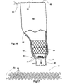
- the inventive graft comprises an upper main portion 59 having an upper edge 60, a lower edge 61 and preferably a tapered middle portion 62 that is tapered towards edge 61.
- Graft portion 62 may be manufactured from any compliant material, such as a knitted fabric material with controlled expansion, even along the entire life of the graft, as it will be very well known for any person skilled in the art.
- the material is preferably a knitted fabric manufactured in a circular loom, as it is also well know to any one skilled in the art.
- the teachings of the inventions are applied to edge 61, as well as to any other part of the graft that it is desired to have an inelastic behavior for purposes of operation as will be explained below.
- FIG. 17 a preferred knitted construction has been illustrated but it is to be remarked that any other construction may be used as long as the concepts of the invention can be applied to the same.
- a firm connection must be guaranteed between the upper main graft portion and the lower leg portion.
- a stent must be, therefore, firmly retained within lower portion 62 of graft portion 59 but, the elastic construction of the graft would not guarantee such desired retention.
- a thread either inelastic or controllably elastic, is arranged at the edge, close to the edge or portion of the graft desired to be converted into inelastic.
- a thread 65 is threaded through the edge loops 66 of the knitted textile as better shown in FIG. 17, and a knot 67 may be made by the physician, his/her assistant or the manufacturer at free ends 71 of the thread before installing the graft into the introducer.
- the diameter of lower edge 61 is restricted to a predetermined maximum value, this predetermined diameter being related to the maximum diameter to which stent 64 may be, or are to be, expanded, whereby the stent, and hence a leg portion 68, is firmly retained against graft portion 62 and prevented to slip off by thread 65.
- the stent should be expanded at such an extent that, in the expanded condition, will have a maximum diameter larger than the predetermined maximum diameter of the inelastic edge.
- a similar thread 69 may be arranged through loops 70 in upper edge 60, however, this thread is not knotted as long as edge 60 should preferably remain entirely elastic to accommodate to the upper aortic neck and its irregularities.
- Threads 65, 69 may be passed through the outermost loops 66, 70 as illustrated or may be conveniently passed through a more inner row of loops.
- Threads 66, 70 may be threaded after the fabric has been manufactured or may be knitted or threaded during the knitting of the fabric, that is forming part of the fabric construction, thus the thread does not threaded on purpose after the knitted fabric has been manufactured.
- the thread has elastic characteristics the elastic elongation the thread can be adopted is always shorter than the one that the knitted fabric can reach because of its yielding capacity provided by the knitting characteristics. That is the elasticity of the thread is a controlled elasticity.
- FIG. 18 The concept of using a thread either to be knotted to restrict a diameter or to remain free is also used in the embodiment shown in FIG. 18, wherein a bifurcated graft trunk portion 72, like the ones disclosed above, is shown.
- Graft portion 72 incorporates the teachings of the diameter restricting thread in pending leg 73 wherein a thread 74 is arranged to a lower edge 75.
- the construction may be the same or similar to the one shown in FIG. 17 and the thread may be knotted to restrict the diameter of edge 75 with the same above explained retention purposes.
- pending leg 76 may include an additional thread 77, passed through the known typical loops of the knitted fabric, with the purpose of pulling from the thread and knotted the same to close leg at a point close to a bifurcation 78 of the graft, in order to convert the bi-iliac aortic graft into a monoiliac aortic graft.
- graft 59 is provided, wherein the graft is intraluminally inserted in the aorta, the aorta having an upper proximal aortic neck and a distal aortic lower portion forming an iliac bifurcation dividing into two iliac arteries.
- the main portion of the graft is placed inside the aorta whereby the portion is firmly retained against the upper aortic neck with lower edge 61 of the graft main portion freely moving inside the aneurysm, then, the upper end of leg portion 68 is inserted inside the lower portion of the main graft portion, and the anchoring means comprising the stent 64 is expanded once at least a part of the stent is inside lower portion 62 and upwardly lower inelastic edge 61.
- Stent 64 is expanded to an extent to define, in the expanded condition, and in at least a section thereof upwardly edge 61, a maximum diameter larger than a predetermined maximum diameter of edge 61, whereby the upper end of the leg portion may be retained within the lower portion of the main portion by the anchoring means, with the inelastic edge encircling the upper end of the graft leg portion and the stent remaining within the graft main portion upwardly of edge 61.
- leg portion 68 includes a plurality of stents, or a long unique stent, along its length. That is, a leg portion stented at the ends thereof or entirely stented with one long or several short stents.
- a knot is made in free ends 71 of the thread in order to define a predetermined maximum diameter of the inelastic edge before placing the main graft portion inside the aorta.
- the stent defines, in the expanded condition, a maximum diameter larger than the predetermined maximum diameter of the inelastic edge.
Priority Applications (1)
| Application Number | Priority Date | Filing Date | Title |
|---|---|---|---|
| DE60023768.0T DE60023768T3 (de) | 1999-02-16 | 2000-02-15 | Aortatransplantat sowie Verfahren zum Ausbessern eines Bauchaortenaneurysmas |
Applications Claiming Priority (2)
| Application Number | Priority Date | Filing Date | Title |
|---|---|---|---|
| US250742 | 1999-02-16 | ||
| US09/250,742 US6162246A (en) | 1999-02-16 | 1999-02-16 | Aortic graft and method of treating abdominal aortic aneurysms |
Publications (4)
| Publication Number | Publication Date |
|---|---|
| EP1029518A2 true EP1029518A2 (fr) | 2000-08-23 |
| EP1029518A3 EP1029518A3 (fr) | 2003-02-26 |
| EP1029518B1 EP1029518B1 (fr) | 2005-11-09 |
| EP1029518B2 EP1029518B2 (fr) | 2015-11-25 |
Family
ID=22948951
Family Applications (1)
| Application Number | Title | Priority Date | Filing Date |
|---|---|---|---|
| EP00890039.1A Expired - Lifetime EP1029518B2 (fr) | 1999-02-16 | 2000-02-15 | Prothèse aortique et méthode d'utilisation pour le traitement d'un anévrisme aortique abdominal |
Country Status (12)
| Country | Link |
|---|---|
| US (1) | US6162246A (fr) |
| EP (1) | EP1029518B2 (fr) |
| AR (1) | AR022487A1 (fr) |
| AT (1) | ATE308942T1 (fr) |
| AU (1) | AU771999B2 (fr) |
| BR (1) | BR0000475B1 (fr) |
| CA (1) | CA2298290C (fr) |
| CY (1) | CY1105496T1 (fr) |
| DE (1) | DE60023768T3 (fr) |
| DK (1) | DK1029518T3 (fr) |
| ES (1) | ES2254127T5 (fr) |
| MX (1) | MXPA00001571A (fr) |
Cited By (11)
| Publication number | Priority date | Publication date | Assignee | Title |
|---|---|---|---|---|
| WO2000074598A1 (fr) * | 1999-06-07 | 2000-12-14 | Boston Scientific Limited | Prosthese intracavitaire modulaire a acces de fil guide ameliore pourvu d'une section de connexion |
| WO2003084440A1 (fr) * | 2002-04-04 | 2003-10-16 | Boston Scientific Limited | Endoprothese vasculaire de longueur reglable |
| EP1803419A1 (fr) * | 2006-01-03 | 2007-07-04 | Cordis Corporation | Stent-greffe prothétique pour le traitement des anévrismes de l'aorte |
| WO2009145901A1 (fr) * | 2008-05-29 | 2009-12-03 | Med Institute, Inc. | Prothèse endoluminale composite discrète |
| US7766954B2 (en) | 2001-12-20 | 2010-08-03 | Trivascular2, Inc. | Advanced endovascular graft |
| US7803178B2 (en) | 2004-01-30 | 2010-09-28 | Trivascular, Inc. | Inflatable porous implants and methods for drug delivery |
| US8784471B2 (en) | 2006-08-31 | 2014-07-22 | Barts And The London Nhs Trust | Blood vessel prosthesis and delivery apparatus |
| US9439758B2 (en) | 2008-02-22 | 2016-09-13 | Barts And The London Nhs Trust | Blood vessel prosthesis and delivery apparatus |
| WO2016160540A1 (fr) * | 2015-03-27 | 2016-10-06 | Eva Corporation | Endogreffons améliorés pour la réparation endovasculaire d'anévrismes aortiques abdominaux |
| US9867727B2 (en) | 1998-02-09 | 2018-01-16 | Trivascular, Inc. | Endovascular graft |
| EP3272314A1 (fr) * | 2016-07-21 | 2018-01-24 | Cook Medical Technologies LLC | Greffe aaa à corps conique |
Families Citing this family (55)
| Publication number | Priority date | Publication date | Assignee | Title |
|---|---|---|---|---|
| US5609627A (en) * | 1994-02-09 | 1997-03-11 | Boston Scientific Technology, Inc. | Method for delivering a bifurcated endoluminal prosthesis |
| US6051020A (en) | 1994-02-09 | 2000-04-18 | Boston Scientific Technology, Inc. | Bifurcated endoluminal prosthesis |
| US6887268B2 (en) * | 1998-03-30 | 2005-05-03 | Cordis Corporation | Extension prosthesis for an arterial repair |
| US6656215B1 (en) | 2000-11-16 | 2003-12-02 | Cordis Corporation | Stent graft having an improved means for attaching a stent to a graft |
| US6214036B1 (en) * | 1998-11-09 | 2001-04-10 | Cordis Corporation | Stent which is easily recaptured and repositioned within the body |
| US6344056B1 (en) * | 1999-12-29 | 2002-02-05 | Edwards Lifesciences Corp. | Vascular grafts for bridging a vessel side branch |
| US6663667B2 (en) | 1999-12-29 | 2003-12-16 | Edwards Lifesciences Corporation | Towel graft means for enhancing tissue ingrowth in vascular grafts |
| US6409756B1 (en) * | 2000-01-24 | 2002-06-25 | Edward G. Murphy | Endovascular aortic graft |
| US7226474B2 (en) | 2000-05-01 | 2007-06-05 | Endovascular Technologies, Inc. | Modular graft component junctions |
| US7666221B2 (en) * | 2000-05-01 | 2010-02-23 | Endovascular Technologies, Inc. | Lock modular graft component junctions |
| US6730119B1 (en) * | 2000-10-06 | 2004-05-04 | Board Of Regents Of The University Of Texas System | Percutaneous implantation of partially covered stents in aneurysmally dilated arterial segments with subsequent embolization and obliteration of the aneurysm cavity |
| ATE346568T1 (de) * | 2001-03-28 | 2006-12-15 | Cook Inc | Modulare stentendoprothese |
| US6814751B2 (en) | 2001-10-12 | 2004-11-09 | Rosengart Todd K | Method and apparatus for performing an anastamosis |
| US7066953B2 (en) * | 2001-10-12 | 2006-06-27 | Rosengart Todd K | Method and apparatus for performing an anastamosis |
| US7708771B2 (en) | 2002-02-26 | 2010-05-04 | Endovascular Technologies, Inc. | Endovascular graft device and methods for attaching components thereof |
| WO2003071929A2 (fr) * | 2002-02-26 | 2003-09-04 | Endovascular Technologies, Inc. | Dispositif de greffe vasculaire |
| US7942924B1 (en) | 2002-03-04 | 2011-05-17 | Endovascular Technologies, Inc. | Staged endovascular graft delivery system |
| US7655036B2 (en) * | 2002-04-24 | 2010-02-02 | Medtronic Vascular, Inc. | Bifurcated endoluminal prosthetic assembly and method |
| US7572286B1 (en) * | 2002-05-13 | 2009-08-11 | Advanced Cardiovascular Systems, Inc. | Stent assembly for the treatment of vulnerable plaque |
| US8518096B2 (en) * | 2002-09-03 | 2013-08-27 | Lifeshield Sciences Llc | Elephant trunk thoracic endograft and delivery system |
| US7025779B2 (en) | 2003-02-26 | 2006-04-11 | Scimed Life Systems, Inc. | Endoluminal device having enhanced affixation characteristics |
| WO2004093746A1 (fr) | 2003-03-26 | 2004-11-04 | The Foundry Inc. | Dispositifs et procedes de traitement d'anevrismes de l'aorte abdominale |
| US20040254628A1 (en) * | 2003-06-13 | 2004-12-16 | Patrice Nazzaro | One-branch stent-graft for bifurcated lumens |
| US7998186B2 (en) | 2003-10-14 | 2011-08-16 | William A. Cook Australia Pty. Ltd. | Introducer for a side branch device |
| EP3031425B1 (fr) * | 2003-10-14 | 2022-03-30 | Cook Medical Technologies LLC | Dispositif d'introduction pour un dispositif de ramification latérale iliaque |
| US7702137B2 (en) | 2004-11-10 | 2010-04-20 | M2S, Inc. | Anatomical visualization and measurement system |
| WO2006093546A1 (fr) * | 2004-12-07 | 2006-09-08 | Medical Metrx Solutions, Inc. | Systeme de visualisation et de mesure anatomiques |
| CA2615535C (fr) | 2005-07-27 | 2013-12-24 | Cook Critical Care Incorporated | Endoprothese couverte et procede d'implantation chirurgicale ouverte |
| US8900287B2 (en) * | 2006-01-13 | 2014-12-02 | Aga Medical Corporation | Intravascular deliverable stent for reinforcement of abdominal aortic aneurysm |
| US8083792B2 (en) | 2006-01-24 | 2011-12-27 | Cordis Corporation | Percutaneous endoprosthesis using suprarenal fixation and barbed anchors |
| WO2008100852A2 (fr) | 2007-02-13 | 2008-08-21 | Abbott Cardiovascular Systems Inc. | Alliages radio-opaques compatibles avec l'irm à utiliser dans les dispositifs médicaux |
| US8906081B2 (en) | 2007-09-13 | 2014-12-09 | W. L. Gore & Associates, Inc. | Stented vascular graft |
| US8663309B2 (en) | 2007-09-26 | 2014-03-04 | Trivascular, Inc. | Asymmetric stent apparatus and method |
| US8226701B2 (en) | 2007-09-26 | 2012-07-24 | Trivascular, Inc. | Stent and delivery system for deployment thereof |
| US8066755B2 (en) | 2007-09-26 | 2011-11-29 | Trivascular, Inc. | System and method of pivoted stent deployment |
| US10159557B2 (en) | 2007-10-04 | 2018-12-25 | Trivascular, Inc. | Modular vascular graft for low profile percutaneous delivery |
| EP2211777B1 (fr) | 2007-10-26 | 2015-09-30 | Cook Medical Technologies LLC | Conduite vasculaire et système de distribution pour placement chirurgical ouvert |
| US8328861B2 (en) | 2007-11-16 | 2012-12-11 | Trivascular, Inc. | Delivery system and method for bifurcated graft |
| US8083789B2 (en) | 2007-11-16 | 2011-12-27 | Trivascular, Inc. | Securement assembly and method for expandable endovascular device |
| US8021413B2 (en) | 2007-12-27 | 2011-09-20 | Cook Medical Technologies Llc | Low profile medical device |
| EP2559402B1 (fr) | 2009-12-01 | 2016-05-04 | Altura Medical, Inc. | Endoprothèse vasculaire modulaires |
| WO2012040240A1 (fr) | 2010-09-20 | 2012-03-29 | Altura Medical, Inc. | Systèmes de pose d'endoprothèse couverte et procédés associés |
| US9155612B2 (en) | 2011-01-10 | 2015-10-13 | Intermountain Invention Management, Llc | Composite stent grafts for in situ assembly and related methods |
| US10335296B2 (en) | 2011-05-17 | 2019-07-02 | The University Of Kentucky Research Foundation | Graft within a graft endoluminal graft |
| US8992595B2 (en) | 2012-04-04 | 2015-03-31 | Trivascular, Inc. | Durable stent graft with tapered struts and stable delivery methods and devices |
| US9498363B2 (en) | 2012-04-06 | 2016-11-22 | Trivascular, Inc. | Delivery catheter for endovascular device |
| US9132025B2 (en) | 2012-06-15 | 2015-09-15 | Trivascular, Inc. | Bifurcated endovascular prosthesis having tethered contralateral leg |
| EP2882381B1 (fr) | 2012-08-10 | 2018-12-26 | Lombard Medical Limited | Système de pose d'endoprothèse |
| US9801721B2 (en) * | 2012-10-12 | 2017-10-31 | St. Jude Medical, Cardiology Division, Inc. | Sizing device and method of positioning a prosthetic heart valve |
| AU2013273849B2 (en) * | 2012-12-26 | 2015-02-12 | Cleveland Clinic Foundation | Endoluminal prosthesis having modular branches and methods of deployment |
| US9737426B2 (en) | 2013-03-15 | 2017-08-22 | Altura Medical, Inc. | Endograft device delivery systems and associated methods |
| JP6718455B2 (ja) | 2015-01-11 | 2020-07-08 | アサイラス メディカル,エルエルシー | 種々の解剖学的特性を有する器官に適合するように構成された外科用大動脈修復ハイブリッド装置および同装置を用いる方法 |
| AR104494A1 (es) | 2016-04-27 | 2017-07-26 | Daniel Barone Hector | Prótesis aórtica para el tratamiento de aneurismas aórticos abdominales |
| EP3573577B1 (fr) * | 2017-01-25 | 2022-10-19 | W. L. Gore & Associates, Inc. | Dispositif de traitement et de prévention de la surcharge de fluide chez des patients présentant une insuffisance cardiaque |
| CA3133857A1 (fr) | 2019-03-20 | 2020-09-24 | inQB8 Medical Technologies, LLC | Implant de dissection aortique |
Citations (7)
| Publication number | Priority date | Publication date | Assignee | Title |
|---|---|---|---|---|
| WO1983003752A1 (fr) | 1982-04-30 | 1983-11-10 | Wallsten Hans Ivar | Prothese comprenant un corps tubulaire expansible ou contractile |
| US4562596A (en) | 1984-04-25 | 1986-01-07 | Elliot Kornberg | Aortic graft, device and method for performing an intraluminal abdominal aortic aneurysm repair |
| WO1990015582A1 (fr) | 1989-06-19 | 1990-12-27 | Trout Hugh H Iii | Procede de greffage et greffe d'aorte pour la reparation d'anevrismes |
| US5609627A (en) | 1994-02-09 | 1997-03-11 | Boston Scientific Technology, Inc. | Method for delivering a bifurcated endoluminal prosthesis |
| US5628788A (en) | 1995-11-07 | 1997-05-13 | Corvita Corporation | Self-expanding endoluminal stent-graft |
| US5632772A (en) | 1993-10-21 | 1997-05-27 | Corvita Corporation | Expandable supportive branched endoluminal grafts |
| US5639278A (en) | 1993-10-21 | 1997-06-17 | Corvita Corporation | Expandable supportive bifurcated endoluminal grafts |
Family Cites Families (8)
| Publication number | Priority date | Publication date | Assignee | Title |
|---|---|---|---|---|
| DE3640745A1 (de) * | 1985-11-30 | 1987-06-04 | Ernst Peter Prof Dr M Strecker | Katheter zum herstellen oder erweitern von verbindungen zu oder zwischen koerperhohlraeumen |
| DE9319267U1 (de) † | 1993-12-15 | 1994-02-24 | Vorwerk Dierk Dr | Aortenendoprothese |
| US5575817A (en) * | 1994-08-19 | 1996-11-19 | Martin; Eric C. | Aorto femoral bifurcation graft and method of implantation |
| US5683449A (en) * | 1995-02-24 | 1997-11-04 | Marcade; Jean Paul | Modular bifurcated intraluminal grafts and methods for delivering and assembling same |
| DE69732411T2 (de) † | 1996-06-20 | 2006-01-19 | Vascutek Ltd., Renfrewshire | Reparieren von Körpergefäßen durch Prothesen |
| US5676697A (en) † | 1996-07-29 | 1997-10-14 | Cardiovascular Dynamics, Inc. | Two-piece, bifurcated intraluminal graft for repair of aneurysm |
| US6030415A (en) † | 1997-01-29 | 2000-02-29 | Endovascular Technologies, Inc. | Bell-bottom modular stent-graft |
| CA2229685C (fr) † | 1997-02-27 | 2003-09-02 | Corvita Corporation | Endoprotheses endoluminales modulaires et methodes d'utilisation |
-
1999
- 1999-02-16 US US09/250,742 patent/US6162246A/en not_active Expired - Lifetime
-
2000
- 2000-02-03 AR ARP000100458A patent/AR022487A1/es active IP Right Grant
- 2000-02-08 AU AU14973/00A patent/AU771999B2/en not_active Ceased
- 2000-02-09 CA CA002298290A patent/CA2298290C/fr not_active Expired - Fee Related
- 2000-02-15 MX MXPA00001571A patent/MXPA00001571A/es active IP Right Grant
- 2000-02-15 ES ES00890039.1T patent/ES2254127T5/es not_active Expired - Lifetime
- 2000-02-15 AT AT00890039T patent/ATE308942T1/de not_active IP Right Cessation
- 2000-02-15 EP EP00890039.1A patent/EP1029518B2/fr not_active Expired - Lifetime
- 2000-02-15 BR BRPI0000475-8A patent/BR0000475B1/pt not_active IP Right Cessation
- 2000-02-15 DE DE60023768.0T patent/DE60023768T3/de not_active Expired - Lifetime
- 2000-02-15 DK DK00890039T patent/DK1029518T3/da active
-
2006
- 2006-02-09 CY CY20061100182T patent/CY1105496T1/el unknown
Patent Citations (7)
| Publication number | Priority date | Publication date | Assignee | Title |
|---|---|---|---|---|
| WO1983003752A1 (fr) | 1982-04-30 | 1983-11-10 | Wallsten Hans Ivar | Prothese comprenant un corps tubulaire expansible ou contractile |
| US4562596A (en) | 1984-04-25 | 1986-01-07 | Elliot Kornberg | Aortic graft, device and method for performing an intraluminal abdominal aortic aneurysm repair |
| WO1990015582A1 (fr) | 1989-06-19 | 1990-12-27 | Trout Hugh H Iii | Procede de greffage et greffe d'aorte pour la reparation d'anevrismes |
| US5632772A (en) | 1993-10-21 | 1997-05-27 | Corvita Corporation | Expandable supportive branched endoluminal grafts |
| US5639278A (en) | 1993-10-21 | 1997-06-17 | Corvita Corporation | Expandable supportive bifurcated endoluminal grafts |
| US5609627A (en) | 1994-02-09 | 1997-03-11 | Boston Scientific Technology, Inc. | Method for delivering a bifurcated endoluminal prosthesis |
| US5628788A (en) | 1995-11-07 | 1997-05-13 | Corvita Corporation | Self-expanding endoluminal stent-graft |
Cited By (17)
| Publication number | Priority date | Publication date | Assignee | Title |
|---|---|---|---|---|
| US10548750B2 (en) | 1998-02-09 | 2020-02-04 | Trivascular, Inc. | Endovascular graft |
| US9867727B2 (en) | 1998-02-09 | 2018-01-16 | Trivascular, Inc. | Endovascular graft |
| US6648913B1 (en) | 1999-06-07 | 2003-11-18 | Scimed Life Systems, Inc. | Guidewire-access modular intraluminal prosthesis with connecting section |
| WO2000074598A1 (fr) * | 1999-06-07 | 2000-12-14 | Boston Scientific Limited | Prosthese intracavitaire modulaire a acces de fil guide ameliore pourvu d'une section de connexion |
| US7766954B2 (en) | 2001-12-20 | 2010-08-03 | Trivascular2, Inc. | Advanced endovascular graft |
| WO2003084440A1 (fr) * | 2002-04-04 | 2003-10-16 | Boston Scientific Limited | Endoprothese vasculaire de longueur reglable |
| US7789903B2 (en) | 2002-04-04 | 2010-09-07 | Boston Scientific Scimed, Inc. | Stent-graft with adjustable length |
| US8182524B2 (en) | 2002-04-04 | 2012-05-22 | Boston Scientific Scimed, Inc. | Stent-graft with adjustable length |
| US8267989B2 (en) | 2004-01-30 | 2012-09-18 | Trivascular, Inc. | Inflatable porous implants and methods for drug delivery |
| US7803178B2 (en) | 2004-01-30 | 2010-09-28 | Trivascular, Inc. | Inflatable porous implants and methods for drug delivery |
| JP2007181701A (ja) * | 2006-01-03 | 2007-07-19 | Cordis Corp | 腹部大動脈瘤の治療用補綴用ステントグラフト |
| EP1803419A1 (fr) * | 2006-01-03 | 2007-07-04 | Cordis Corporation | Stent-greffe prothétique pour le traitement des anévrismes de l'aorte |
| US8784471B2 (en) | 2006-08-31 | 2014-07-22 | Barts And The London Nhs Trust | Blood vessel prosthesis and delivery apparatus |
| US9439758B2 (en) | 2008-02-22 | 2016-09-13 | Barts And The London Nhs Trust | Blood vessel prosthesis and delivery apparatus |
| WO2009145901A1 (fr) * | 2008-05-29 | 2009-12-03 | Med Institute, Inc. | Prothèse endoluminale composite discrète |
| WO2016160540A1 (fr) * | 2015-03-27 | 2016-10-06 | Eva Corporation | Endogreffons améliorés pour la réparation endovasculaire d'anévrismes aortiques abdominaux |
| EP3272314A1 (fr) * | 2016-07-21 | 2018-01-24 | Cook Medical Technologies LLC | Greffe aaa à corps conique |
Also Published As
| Publication number | Publication date |
|---|---|
| MXPA00001571A (es) | 2002-03-08 |
| EP1029518B1 (fr) | 2005-11-09 |
| CA2298290C (fr) | 2008-12-23 |
| US6162246A (en) | 2000-12-19 |
| AU771999B2 (en) | 2004-04-08 |
| ES2254127T3 (es) | 2006-06-16 |
| DE60023768D1 (de) | 2005-12-15 |
| DE60023768T2 (de) | 2006-08-03 |
| AU1497300A (en) | 2000-08-17 |
| EP1029518B2 (fr) | 2015-11-25 |
| ATE308942T1 (de) | 2005-11-15 |
| BR0000475A (pt) | 2000-11-28 |
| BR0000475B1 (pt) | 2009-01-13 |
| EP1029518A3 (fr) | 2003-02-26 |
| DE60023768T3 (de) | 2016-04-07 |
| CY1105496T1 (el) | 2010-04-28 |
| DK1029518T3 (da) | 2006-03-27 |
| ES2254127T5 (es) | 2016-03-15 |
| AR022487A1 (es) | 2002-09-04 |
| CA2298290A1 (fr) | 2000-08-16 |
Similar Documents
| Publication | Publication Date | Title |
|---|---|---|
| US6162246A (en) | Aortic graft and method of treating abdominal aortic aneurysms | |
| EP2749252B1 (fr) | Système de prothèse | |
| US5676697A (en) | Two-piece, bifurcated intraluminal graft for repair of aneurysm | |
| US6676699B2 (en) | Stent graft with integrated valve device and method | |
| AU738826B2 (en) | Endovascular prosthetic device, and method of use | |
| EP1401357B1 (fr) | Implant fixe de maniere amelioree dans une lumiere du corps | |
| AU725117B2 (en) | Bifurcated vascular graft deployment device | |
| EP2497444B1 (fr) | Conception et ensemble de greffons d'endoprothèse fenêtrés | |
| US8663307B2 (en) | Endoluminal prosthesis | |
| CA2313080C (fr) | Extenseurs aortiques endoluminaux | |
| US6918926B2 (en) | System for transrenal/intraostial fixation of endovascular prosthesis | |
| US6878161B2 (en) | Stent graft loading and deployment device and method | |
| CA2737438C (fr) | Dispositif d'introduction permettant de deployer une prothese endovasculaire dans une lumiere courbe et prothese endovasculaire associee | |
| US5800521A (en) | Prosthetic graft and method for aneurysm repair | |
| US20030204249A1 (en) | Endovascular stent graft and fixation cuff | |
| WO2004017868A1 (fr) | Fixation asymetrique de stent greffe | |
| WO2010124095A1 (fr) | Dispositif de routage endovasculaire et procédé afférent | |
| EP0836449A1 (fr) | Greffe prosthetique et procede de reparation d'un anevrisme | |
| EP2758001A1 (fr) | Procédé et appareil pour la thérapie endovasculaire d'une pathologie aortique | |
| US10849732B2 (en) | Prosthesis for treating abdominal aortic aneurysm and method | |
| US20220265416A1 (en) | Closure mechanism | |
| GB2517401A (en) | Graft with moveable fenestration |
Legal Events
| Date | Code | Title | Description |
|---|---|---|---|
| PUAI | Public reference made under article 153(3) epc to a published international application that has entered the european phase |
Free format text: ORIGINAL CODE: 0009012 |
|
| AK | Designated contracting states |
Kind code of ref document: A2 Designated state(s): AT BE CH CY DE DK ES FI FR GB GR IE IT LI LU MC NL PT SE |
|
| AX | Request for extension of the european patent |
Free format text: AL;LT;LV;MK;RO;SI |
|
| PUAL | Search report despatched |
Free format text: ORIGINAL CODE: 0009013 |
|
| AK | Designated contracting states |
Kind code of ref document: A3 Designated state(s): AT BE CH CY DE DK ES FI FR GB GR IE IT LI LU MC NL PT SE |
|
| AX | Request for extension of the european patent |
Extension state: AL LT LV MK RO SI |
|
| 17P | Request for examination filed |
Effective date: 20030826 |
|
| AKX | Designation fees paid |
Designated state(s): AT BE CH CY DE DK ES FI FR GB GR IE IT LI LU MC NL PT SE |
|
| 17Q | First examination report despatched |
Effective date: 20040521 |
|
| GRAP | Despatch of communication of intention to grant a patent |
Free format text: ORIGINAL CODE: EPIDOSNIGR1 |
|
| GRAS | Grant fee paid |
Free format text: ORIGINAL CODE: EPIDOSNIGR3 |
|
| GRAA | (expected) grant |
Free format text: ORIGINAL CODE: 0009210 |
|
| AK | Designated contracting states |
Kind code of ref document: B1 Designated state(s): AT BE CH CY DE DK ES FI FR GB GR IE IT LI LU MC NL PT SE |
|
| REG | Reference to a national code |
Ref country code: GB Ref legal event code: FG4D |
|
| REG | Reference to a national code |
Ref country code: CH Ref legal event code: EP |
|
| REG | Reference to a national code |
Ref country code: IE Ref legal event code: FG4D |
|
| REF | Corresponds to: |
Ref document number: 60023768 Country of ref document: DE Date of ref document: 20051215 Kind code of ref document: P |
|
| REG | Reference to a national code |
Ref country code: CH Ref legal event code: NV Representative=s name: E. BLUM & CO. PATENTANWAELTE Ref country code: SE Ref legal event code: TRGR |
|
| REG | Reference to a national code |
Ref country code: DK Ref legal event code: T3 |
|
| REG | Reference to a national code |
Ref country code: GR Ref legal event code: EP Ref document number: 20060400493 Country of ref document: GR |
|
| REG | Reference to a national code |
Ref country code: ES Ref legal event code: FG2A Ref document number: 2254127 Country of ref document: ES Kind code of ref document: T3 |
|
| ET | Fr: translation filed | ||
| PLBI | Opposition filed |
Free format text: ORIGINAL CODE: 0009260 |
|
| PUAH | Patent maintained in amended form |
Free format text: ORIGINAL CODE: 0009272 |
|
| PUAD | Information related to the publication of a b2 document modified or deleted |
Free format text: ORIGINAL CODE: 0009399EPPU |
|
| PLAX | Notice of opposition and request to file observation + time limit sent |
Free format text: ORIGINAL CODE: EPIDOSNOBS2 |
|
| 26 | Opposition filed |
Opponent name: COOK INCORPORATED Effective date: 20060808 |
|
| 27A | Patent maintained in amended form |
Effective date: 20061004 |
|
| AK | Designated contracting states |
Kind code of ref document: B2 Designated state(s): AT BE CH CY DE DK ES FI FR GB GR IE IT LI LU MC NL PT SE |
|
| D27A | Patent maintained in amended form (deleted) | ||
| DB2 | B2 document published (deleted) | ||
| REG | Reference to a national code |
Ref country code: CH Ref legal event code: AEN Free format text: AUFRECHTERHALTUNG DES PATENTES IN GEAENDERTER FORM |
|
| NLR1 | Nl: opposition has been filed with the epo |
Opponent name: COOK INCORPORATED |
|
| NLR2 | Nl: decision of opposition |
Effective date: 20061004 |
|
| EN | Fr: translation not filed | ||
| PG25 | Lapsed in a contracting state [announced via postgrant information from national office to epo] |
Ref country code: DE Free format text: LAPSE BECAUSE OF FAILURE TO SUBMIT A TRANSLATION OF THE DESCRIPTION OR TO PAY THE FEE WITHIN THE PRESCRIBED TIME-LIMIT Effective date: 20070105 |
|
| PLAF | Information modified related to communication of a notice of opposition and request to file observations + time limit |
Free format text: ORIGINAL CODE: EPIDOSCOBS2 |
|
| REG | Reference to a national code |
Ref country code: CH Ref legal event code: PL |
|
| REG | Reference to a national code |
Ref country code: CH Ref legal event code: PK Ref document number: 1029518 Country of ref document: CH Free format text: DIE AUFRECHTERHALTUNG IN GEAENDERTER FORM VOM 04.10.2006 WURDE VOM EPA WIDERRUFEN. Ref country code: CH Ref legal event code: AEN Free format text: DIE VERFUEGUNG NICHTEINTRITT DER WIRKUNG CH/LI VOM 09.11.2005 WIRD ANNULLIERT, WEIL DER GRUND FUER DIE VERFUEGUNG (NICHTEINREICHUNG DER UEBERSETZUNG Z |
|
| PLBB | Reply of patent proprietor to notice(s) of opposition received |
Free format text: ORIGINAL CODE: EPIDOSNOBS3 |
|
| REG | Reference to a national code |
Ref country code: CH Ref legal event code: PFA Owner name: BARONE, HECTOR DANIEL Free format text: BARONE, HECTOR DANIEL#MAZA 1948#CAPITAL FEDERAL, BS.AS. (AR) -TRANSFER TO- BARONE, HECTOR DANIEL#MAZA 1948#CAPITAL FEDERAL, BS.AS. (AR) |
|
| PGFP | Annual fee paid to national office [announced via postgrant information from national office to epo] |
Ref country code: GR Payment date: 20070110 Year of fee payment: 8 |
|
| RDAF | Communication despatched that patent is revoked |
Free format text: ORIGINAL CODE: EPIDOSNREV1 |
|
| PG25 | Lapsed in a contracting state [announced via postgrant information from national office to epo] |
Ref country code: GR Free format text: LAPSE BECAUSE OF FAILURE TO SUBMIT A TRANSLATION OF THE DESCRIPTION OR TO PAY THE FEE WITHIN THE PRESCRIBED TIME-LIMIT Effective date: 20070105 |
|
| APAH | Appeal reference modified |
Free format text: ORIGINAL CODE: EPIDOSCREFNO |
|
| APBP | Date of receipt of notice of appeal recorded |
Free format text: ORIGINAL CODE: EPIDOSNNOA2O |
|
| APBQ | Date of receipt of statement of grounds of appeal recorded |
Free format text: ORIGINAL CODE: EPIDOSNNOA3O |
|
| NLV4 | Nl: lapsed or anulled due to non-payment of the annual fee |
Effective date: 20080901 |
|
| PGFP | Annual fee paid to national office [announced via postgrant information from national office to epo] |
Ref country code: CY Payment date: 20090205 Year of fee payment: 10 |
|
| PGFP | Annual fee paid to national office [announced via postgrant information from national office to epo] |
Ref country code: MC Payment date: 20090203 Year of fee payment: 10 |
|
| PG25 | Lapsed in a contracting state [announced via postgrant information from national office to epo] |
Ref country code: FR Free format text: LAPSE BECAUSE OF NON-PAYMENT OF DUE FEES Effective date: 20080227 |
|
| PG25 | Lapsed in a contracting state [announced via postgrant information from national office to epo] |
Ref country code: MC Free format text: LAPSE BECAUSE OF NON-PAYMENT OF DUE FEES Effective date: 20100301 |
|
| PG25 | Lapsed in a contracting state [announced via postgrant information from national office to epo] |
Ref country code: CY Free format text: LAPSE BECAUSE OF NON-PAYMENT OF DUE FEES Effective date: 20100310 |
|
| PGFP | Annual fee paid to national office [announced via postgrant information from national office to epo] |
Ref country code: LU Payment date: 20110210 Year of fee payment: 12 Ref country code: CH Payment date: 20110216 Year of fee payment: 12 Ref country code: AT Payment date: 20110214 Year of fee payment: 12 |
|
| REG | Reference to a national code |
Ref country code: FR Ref legal event code: EERR Free format text: CORRECTION DE BOPI 06/52 - 3.2. |
|
| REG | Reference to a national code |
Ref country code: CH Ref legal event code: NV Representative=s name: MESSERSCHMIDT PATENTE, MARKEN & DESIGN Ref country code: CH Ref legal event code: PUE Owner name: LAVANT INTERNATIONAL S.A. Free format text: BARONE, HECTOR DANIEL#MAZA 1948#CAPITAL FEDERAL, BS.AS. (AR) -TRANSFER TO- LAVANT INTERNATIONAL S.A.#25 DE MAYO 465 APARTADO 501#MONTEVIDEO (UY) |
|
| REG | Reference to a national code |
Ref country code: GB Ref legal event code: 732E Free format text: REGISTERED BETWEEN 20110609 AND 20110615 |
|
| REG | Reference to a national code |
Ref country code: DE Ref legal event code: R082 Ref document number: 60023768 Country of ref document: DE Representative=s name: KAUFMANN & STUMPF PATENTANWALTS-PARTNERSCHAFT, DE |
|
| PGFP | Annual fee paid to national office [announced via postgrant information from national office to epo] |
Ref country code: GB Payment date: 20110214 Year of fee payment: 12 |
|
| REG | Reference to a national code |
Ref country code: NL Ref legal event code: SD Effective date: 20110829 |
|
| REG | Reference to a national code |
Ref country code: DE Ref legal event code: R081 Ref document number: 60023768 Country of ref document: DE Owner name: LAVANT INTERNATIONAL S.A., UY Free format text: FORMER OWNER: BARONE, HECTOR DANIEL, CAPITAL FEDERAL, AR Effective date: 20110721 Ref country code: DE Ref legal event code: R082 Ref document number: 60023768 Country of ref document: DE Representative=s name: STUMPF PATENTANWAELTE PARTGMBB, DE Effective date: 20110721 |
|
| PGFP | Annual fee paid to national office [announced via postgrant information from national office to epo] |
Ref country code: IE Payment date: 20110722 Year of fee payment: 12 |
|
| REG | Reference to a national code |
Ref country code: FR Ref legal event code: TP Owner name: LAVANT INTERNATIONAL S.A., UY Effective date: 20111011 |
|
| REG | Reference to a national code |
Ref country code: PT Ref legal event code: PC4A Owner name: LAVANT INTERNATIONAL S.A., UY Effective date: 20120126 |
|
| REG | Reference to a national code |
Ref country code: AT Ref legal event code: PC Ref document number: 308942 Country of ref document: AT Kind code of ref document: T Owner name: LAVANT INTERNATIONAL S.A., UY Effective date: 20120105 |
|
| PGFP | Annual fee paid to national office [announced via postgrant information from national office to epo] |
Ref country code: PT Payment date: 20120110 Year of fee payment: 13 |
|
| PGFP | Annual fee paid to national office [announced via postgrant information from national office to epo] |
Ref country code: DK Payment date: 20120216 Year of fee payment: 13 Ref country code: BE Payment date: 20120221 Year of fee payment: 13 Ref country code: FI Payment date: 20120216 Year of fee payment: 13 |
|
| REG | Reference to a national code |
Ref country code: CH Ref legal event code: PL |
|
| GBPC | Gb: european patent ceased through non-payment of renewal fee |
Effective date: 20120215 |
|
| PG25 | Lapsed in a contracting state [announced via postgrant information from national office to epo] |
Ref country code: CH Free format text: LAPSE BECAUSE OF NON-PAYMENT OF DUE FEES Effective date: 20120229 Ref country code: LI Free format text: LAPSE BECAUSE OF NON-PAYMENT OF DUE FEES Effective date: 20120229 |
|
| REG | Reference to a national code |
Ref country code: IE Ref legal event code: MM4A |
|
| REG | Reference to a national code |
Ref country code: AT Ref legal event code: MM01 Ref document number: 308942 Country of ref document: AT Kind code of ref document: T Effective date: 20120215 |
|
| PG25 | Lapsed in a contracting state [announced via postgrant information from national office to epo] |
Ref country code: AT Free format text: LAPSE BECAUSE OF NON-PAYMENT OF DUE FEES Effective date: 20120215 Ref country code: GB Free format text: LAPSE BECAUSE OF NON-PAYMENT OF DUE FEES Effective date: 20120215 Ref country code: IE Free format text: LAPSE BECAUSE OF NON-PAYMENT OF DUE FEES Effective date: 20120215 |
|
| APBU | Appeal procedure closed |
Free format text: ORIGINAL CODE: EPIDOSNNOA9O |
|
| REG | Reference to a national code |
Ref country code: PT Ref legal event code: MM4A Free format text: LAPSE DUE TO NON-PAYMENT OF FEES Effective date: 20130816 |
|
| BERE | Be: lapsed |
Owner name: *LAVANT INTERNATIONAL S.A. Effective date: 20130228 |
|
| REG | Reference to a national code |
Ref country code: DK Ref legal event code: EBP |
|
| PG25 | Lapsed in a contracting state [announced via postgrant information from national office to epo] |
Ref country code: FI Free format text: LAPSE BECAUSE OF NON-PAYMENT OF DUE FEES Effective date: 20130215 Ref country code: PT Free format text: LAPSE BECAUSE OF NON-PAYMENT OF DUE FEES Effective date: 20130816 |
|
| PG25 | Lapsed in a contracting state [announced via postgrant information from national office to epo] |
Ref country code: BE Free format text: LAPSE BECAUSE OF NON-PAYMENT OF DUE FEES Effective date: 20130228 Ref country code: DK Free format text: LAPSE BECAUSE OF NON-PAYMENT OF DUE FEES Effective date: 20130228 |
|
| PG25 | Lapsed in a contracting state [announced via postgrant information from national office to epo] |
Ref country code: LU Free format text: LAPSE BECAUSE OF NON-PAYMENT OF DUE FEES Effective date: 20120215 |
|
| RAP2 | Party data changed (patent owner data changed or rights of a patent transferred) |
Owner name: LAVANT INTERNATIONAL S.A. |
|
| RIN2 | Information on inventor provided after grant (corrected) |
Inventor name: BARONE HECTOR DANIEL |
|
| REG | Reference to a national code |
Ref country code: FR Ref legal event code: PLFP Year of fee payment: 16 |
|
| PUAH | Patent maintained in amended form |
Free format text: ORIGINAL CODE: 0009272 |
|
| STAA | Information on the status of an ep patent application or granted ep patent |
Free format text: STATUS: PATENT MAINTAINED AS AMENDED |
|
| 27A | Patent maintained in amended form |
Effective date: 20151125 |
|
| AK | Designated contracting states |
Kind code of ref document: B2 Designated state(s): AT BE CH CY DE DK ES FI FR GB GR IE IT LI LU MC NL PT SE |
|
| REG | Reference to a national code |
Ref country code: DE Ref legal event code: R102 Ref document number: 60023768 Country of ref document: DE |
|
| REG | Reference to a national code |
Ref country code: SE Ref legal event code: RPEO Ref country code: FR Ref legal event code: PLFP Year of fee payment: 17 |
|
| REG | Reference to a national code |
Ref country code: ES Ref legal event code: DC2A Ref document number: 2254127 Country of ref document: ES Kind code of ref document: T5 Effective date: 20160315 |
|
| REG | Reference to a national code |
Ref country code: NL Ref legal event code: FP |
|
| REG | Reference to a national code |
Ref country code: FR Ref legal event code: PLFP Year of fee payment: 18 |
|
| REG | Reference to a national code |
Ref country code: FR Ref legal event code: PLFP Year of fee payment: 19 |
|
| PGFP | Annual fee paid to national office [announced via postgrant information from national office to epo] |
Ref country code: NL Payment date: 20180223 Year of fee payment: 19 |
|
| PGFP | Annual fee paid to national office [announced via postgrant information from national office to epo] |
Ref country code: ES Payment date: 20180307 Year of fee payment: 19 |
|
| PGFP | Annual fee paid to national office [announced via postgrant information from national office to epo] |
Ref country code: SE Payment date: 20180223 Year of fee payment: 19 Ref country code: FR Payment date: 20180223 Year of fee payment: 19 Ref country code: IT Payment date: 20180226 Year of fee payment: 19 |
|
| PGFP | Annual fee paid to national office [announced via postgrant information from national office to epo] |
Ref country code: DE Payment date: 20180405 Year of fee payment: 19 |
|
| REG | Reference to a national code |
Ref country code: DE Ref legal event code: R119 Ref document number: 60023768 Country of ref document: DE |
|
| REG | Reference to a national code |
Ref country code: SE Ref legal event code: EUG |
|
| REG | Reference to a national code |
Ref country code: NL Ref legal event code: MM Effective date: 20190301 |
|
| PG25 | Lapsed in a contracting state [announced via postgrant information from national office to epo] |
Ref country code: SE Free format text: LAPSE BECAUSE OF NON-PAYMENT OF DUE FEES Effective date: 20190216 |
|
| PG25 | Lapsed in a contracting state [announced via postgrant information from national office to epo] |
Ref country code: DE Free format text: LAPSE BECAUSE OF NON-PAYMENT OF DUE FEES Effective date: 20190903 Ref country code: NL Free format text: LAPSE BECAUSE OF NON-PAYMENT OF DUE FEES Effective date: 20190301 |
|
| PG25 | Lapsed in a contracting state [announced via postgrant information from national office to epo] |
Ref country code: IT Free format text: LAPSE BECAUSE OF NON-PAYMENT OF DUE FEES Effective date: 20190215 Ref country code: FR Free format text: LAPSE BECAUSE OF NON-PAYMENT OF DUE FEES Effective date: 20190228 |
|
| REG | Reference to a national code |
Ref country code: ES Ref legal event code: FD2A Effective date: 20200327 |
|
| PG25 | Lapsed in a contracting state [announced via postgrant information from national office to epo] |
Ref country code: ES Free format text: LAPSE BECAUSE OF NON-PAYMENT OF DUE FEES Effective date: 20190216 |