EP1029451B1 - Diffuseur pour substances volatiles - Google Patents
Diffuseur pour substances volatiles Download PDFInfo
- Publication number
- EP1029451B1 EP1029451B1 EP00102705A EP00102705A EP1029451B1 EP 1029451 B1 EP1029451 B1 EP 1029451B1 EP 00102705 A EP00102705 A EP 00102705A EP 00102705 A EP00102705 A EP 00102705A EP 1029451 B1 EP1029451 B1 EP 1029451B1
- Authority
- EP
- European Patent Office
- Prior art keywords
- support
- volatile
- cavity
- heater
- table top
- Prior art date
- Legal status (The legal status is an assumption and is not a legal conclusion. Google has not performed a legal analysis and makes no representation as to the accuracy of the status listed.)
- Expired - Lifetime
Links
Images


Classifications
-
- A—HUMAN NECESSITIES
- A01—AGRICULTURE; FORESTRY; ANIMAL HUSBANDRY; HUNTING; TRAPPING; FISHING
- A01M—CATCHING, TRAPPING OR SCARING OF ANIMALS; APPARATUS FOR THE DESTRUCTION OF NOXIOUS ANIMALS OR NOXIOUS PLANTS
- A01M1/00—Stationary means for catching or killing insects
- A01M1/20—Poisoning, narcotising, or burning insects
- A01M1/2022—Poisoning or narcotising insects by vaporising an insecticide
- A01M1/2061—Poisoning or narcotising insects by vaporising an insecticide using a heat source
- A01M1/2077—Poisoning or narcotising insects by vaporising an insecticide using a heat source using an electrical resistance as heat source
-
- A—HUMAN NECESSITIES
- A61—MEDICAL OR VETERINARY SCIENCE; HYGIENE
- A61L—METHODS OR APPARATUS FOR STERILISING MATERIALS OR OBJECTS IN GENERAL; DISINFECTION, STERILISATION OR DEODORISATION OF AIR; CHEMICAL ASPECTS OF BANDAGES, DRESSINGS, ABSORBENT PADS OR SURGICAL ARTICLES; MATERIALS FOR BANDAGES, DRESSINGS, ABSORBENT PADS OR SURGICAL ARTICLES
- A61L9/00—Disinfection, sterilisation or deodorisation of air
- A61L9/015—Disinfection, sterilisation or deodorisation of air using gaseous or vaporous substances, e.g. ozone
- A61L9/02—Disinfection, sterilisation or deodorisation of air using gaseous or vaporous substances, e.g. ozone using substances evaporated in the air by heating or combustion
- A61L9/03—Apparatus therefor
-
- A—HUMAN NECESSITIES
- A01—AGRICULTURE; FORESTRY; ANIMAL HUSBANDRY; HUNTING; TRAPPING; FISHING
- A01M—CATCHING, TRAPPING OR SCARING OF ANIMALS; APPARATUS FOR THE DESTRUCTION OF NOXIOUS ANIMALS OR NOXIOUS PLANTS
- A01M2200/00—Kind of animal
- A01M2200/01—Insects
- A01M2200/012—Flying insects
Definitions
- This invention relates to dispensing volatile materials such as insecticides, insect repellents, and fragrances. More particularly, it relates to devices containing a volatile material which are employed in conjunction with an electrical or other heating apparatus.
- Mats such as shown in US-A-4,214,146, have similar problems, and also have significant problems in that the mats are exposed to different temperatures across the mat surface.
- low-cost existing heaters often have hotter regions at certain points along their burner surface. The mats therefore had somewhat inefficient vaporization.
- the problem of heat distributors is addressed in document GB-A-2302507.
- the heating element is embedded in a relatively bulky platform, the surface of which comprises a conductive plate.
- the volatile substance which may be contained in a tray, rests on the conductive plate.
- the invention provides a table which is suitable to dispense volatile vapors when heated.
- the table has a tabletop with a pan-like cavity in its upper surface.
- a volatile material is placed in the cavity.
- a support extends downwardly from the table top radially outward of the cavity, the support being constructed and arranged so that when the table is placed on a surface of a heater an air gap is left between the underside of the pan-like cavity and the heating surface of the heater.
- the volatile material is selected from the group consisting of insecticides, insect repellents, fragrances, and deodorizers.
- a solid substrate (such as cellulose) may be positioned in the cavity, with the substrate being impregnated with the volatile material.
- a permeable membrane may extend over the cavity, the tabletop may be made of a thermally conductive material such as a metal, suitable plastic, ceramic, or the like, and the support may be made of thermally insulated material such as a heat-resistant plastic, cellulose material, or ceramic.
- the invention provides a device for dispensing volatile vapors including a heater having a heated surface and a table, of the kind referred to above, positioned on the heating surface.
- the heater is either an electrical resistance heater or a positive temperature co-efficient heater, also referred to as a "PTC heater”.
- the table top and support are formed as two separate units. They are connected together by tabs on the support, by adhesive binding between the support and the table top, and/or by bending side portions of the table top over the support.
- the present invention provides a way of holding the volatile up off the burner unit so that there is a temperature step-down before the bottom of the cavity is exposed to heat. Further, the air gap and preferred metal structure serve to spread the heat more uniformly across the cavity. This leads to more efficient use of expensive volatiles as well as reduces degradation due to exposure to excessive temperature over prolonged periods. As a result, inserts can be designed for use for a week, a month, or even several months.
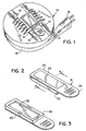
- Fig. 1 there is shown an electrical heater, generally 10.
- the heater is the FUYI VAPE heater previously described, except that the mat previously used with that heater has been replaced with a table of the present invention.
- the heater is an electrical-resistance heater, and has a flat, upwardly exposed plate 12 adjacent to which is placed a table 14 of the present invention.
- An electrical plug 16 (preferably of the self-retracting type) supplies electricity to the heating plate 12 by means of electrical cord 17. During non-use it is almost entirely contained in lower housing 18. As shown at 21, six safety grids are provided (five of which are broken away in Fig. 1 for purposes of illustration).
- the FUYI VAPE heater is described as a suitable heater, the device of the invention is adapted for use with a wide variety of other electrical and non-electrical heaters available for heating conventional mosquito mats.
- a conventional, positive temperature co-efficient heater may be substituted for the resistance heater and is preferred in many applications, and other sources of heat, such as flame or catalytically combusted fuel also may be substituted and are widely known to the art.
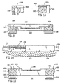
- table 14 has a table top 20 made of aluminum (or other metal) having an upwardly-facing cavity 22.
- the table top 20 can be made of heat-resistant plastic, ceramics, or any otherwise suitable heat resistant material that can transfer heat from the heater to the remaining parts of the table 14.
- a solid substrate 24 is made of a porous material such as paper or other cellulose-based material. Other solid porous substrates could also be used, such as sintered glass, ceramic, plastic beads, natural or synthetic fabrics, and other absorbent and adsorbent materials.
- the substrate/mat 24 is impregnated with a volatile 26 and then placed in the cavity 22. The volatile is released from the substrate 24 when the table is heated. Gels and suitably contained liquids can be used in the cavity 22 instead of the solid substrate 24.
- a permeable membrane 28 that is preferably a laminated membrane having an lower layer which is polyethylene terephthalate and an upper layer which is polyethylene. Membrane 28 further slows release of the volatile 26 from the substrate 24 when the substrate is heated by the heating plate 12.
- a non-porous removable cover (not shown) is placed over layer 28. See e.g. U.S. patent 4,145,001.
- the membrane 28 can be one that presents so little resistance to the escape of vapors that it serves only to confine and protect the source of volatile, whether in liquid, gel, or solid form. However, and preferably, the membrane 28 is selected to restrict volatile release to a desired extent, slowing volatile release from the table and thereby allowing control over the useful life of the table.
- a support 30 Extending downwardly from table top 20 is a support 30, which in one embodiment surrounds the sides of the lower portion of cavity 22. It should, at minimum, have a portion that extends farther outward than the bottom of the cavity 22. In this regard, by “radially outward” we mean that some portion of the structure is radially outward, regardless of whether at the side or below the cavity. In an especially preferred form, none of the support is immediately below the cavity.
- the support can be made of an insulative material such as a temperature-resistant cellulosic material or foam or other heat resistant and flame retardant plastic. It can be secured to the table top by a friction fit around the sides of the cavity, by an adhesive such as epoxy, urethane, or acrylic adhesive, or by other means such as double sided tape.
- an adhesive such as epoxy, urethane, or acrylic adhesive
- the support 30 is designed to rest on heating plate 12, preferably straddling the burner surface. It thereby supports the cavity 22 (and thus the volatile) above the heating plate 12 with an air gap 34 therebetween.
- a handle 35 illustrated in Fig. 1, extending from at least one and, optionally and sometimes preferably, two edge locations of the table top 20 for facilitating the insertion and removal of the table 14 on burner plate 12 under safety grids 19.
- Handle 35 also provides a useful heat sink and radiator for drawing the heat out from cavity 22 and exhausting it to the surrounding air. This effect aids in the even heating of table 20 and especially in controlling and reducing the temperature of the table.
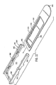
- FIGs. 5-15 Alternative embodiments are shown in Figs. 5-15 where similar numerals designate similar components, except with the numerals having an "A", “B", “C”, “D” or “E” suffix.
- Support 30A is composed of the same material as top 20A (preferably both aluminum). It is formed as one piece during a stamping operation, albeit it has two opposing table legs 31A and 33A which can be bent to positions shown in Fig. 5 (to provide support of the cavity 22A above a heating plate).
- embodiment 14B is formed in two separate components with support 30B being connected to table top 20B by means of the tabs 38B. These are spaced from the upwardly facing surface 40B so that side portions 37B and 39B of the table top 20B can be slightly flexed and inserted therebetween as seen in Fig. 8. This is facilitated by the table top 20B being composed of a thin flexible material such as aluminum.
- Support 30B has a plurality of foot members 31B which position the support 30B above a heating plate 12B with an air gap 34B. Cavity 22B (with volatile 26B) are positioned in opening 41B of support 30B at this point. This affords air circulation from the outside to the air gap 34B and accordingly a cooler operation ( see especially Fig. 10). Support 30B can be injection molded from a crystalline heat-resistant PET resinous plastic or any suitable heat-resistant plastic, among the many available.
- embodiment 14C is similar to embodiment 14B except that instead of portions 37C and 39C of table top 20C being flexed and inserted under tabs 38C, they are slid between the tabs 38C and the surface 40C of the table top 20C.
- the spacing of the tabs 38C from the top surface 40C provides a slide track for the table top 20C.
- An end wall of the support 30C is not present so as to allow passage of cavity 22C into opening 41C. This is indicated at numeral 45C.
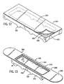
- FIGs. 12-14 Another support 30D is shown in Figs. 12-14. It does not employ the fastening or slide tabs 38B/38C shown in embodiments 14B and 14C, respectively. Instead, a peel-away strip 42D is used. An adhesive 43D is placed on the top surface 40D of support 30D for connection to the bottom sections of side portions 37D and 39D of table top 20D. This results in the table 14D shown in Figs. 13 and 14.
- the table top 20E has flexible side flanges 44E and 45E. These are bent over and connected by frictional engagement to support 30E by crimping over the tops 48E and side edges 49E of the support member 30E. This provides an air gap 34E between cavity 22E and a heating plate such as 12B.
- An important feature of the invention is that at least part of the support (preferably all) is not directly under the cavity, so as to thereby create an air gap.
- This gap slows heat transfer from the heating plate 12, and thus creates a step-down in temperature from the burner plate temperature and helps to evenly distribute the heat across the floor of cavity 22 (with a resulting slower release of insecticide and less heat-caused degradation of insecticide).
- Figs. 6-11 are particularly well suited for use as they not only provide an air gap, they also allow for air to pass sideways between the air gap and the outside. Slower release, assisted by permeable membranes 28 and 28A, results in sustained release of the insecticide over a longer period, thereby permitting inserts to be created which can be effectively used for a week or longer.
- insecticide 26 has been illustrated in conjunction with the impregnation of a solid substrate 24, a liquid or gel could be used without the solid substrate, in conjunction with porous membrane 28. See e.g. U.S. patent 5,645,845 for gel-based systems. In one form, we used a mixture of transfluthrin with a silica gel such as the gel sold under the trade name Cabosil.
- the volatile material is preferably one of (or mixtures of) known insecticides and insect repellents. Particularly preferred are organic phosphorous insecticides, lipidamide insecticides, natural repellents as citronella oil, natural pyrethrins and pyrethrum extract, and synthetic pyrethroids.
- Suitable synthetic pyrethroids are acrinathrin, allethrin as D-allethrin, Pynamin®, benfluthrin, bifenthrin, bioallethrin as Pynamin Forte®, S-bioallethrin, esbiothrin, esbiol, bioresmethrin, cycloprothrin, cyfluthrin, beta-cyfluthrin, cyhalothrin, lambda-cyhalothrin, cypermethrin, alpha-cypermethrin, beta-cypermethrin, cyphenothrin, deltamethrin, empenthrin, esfenvalerate, fenpropathrin, fenvalerate, flucythrinate, taufluvalinate, kadethrin, permethrin, phenothrin, prallethrin as Eto
- Deodorizers may also be used such as a terpene based deodorizer fragrance.
- Antioxidants may also be delivered in this manner.
- disinfectants such as glycols, trimethylene, and dipropylene.
- organic acids which are compatible with the use of the substrate and the atmosphere can also be utilized.
- top and downwardly/bottom are used herein with respect to the most typical orientation. However, for heater units with vertical or other heating surfaces these terms are intended to mean directions away from and toward the heater, respectively.
- the invention provides a device for dispensing volatile materials such as insecticides.
- the device is particularly useful in controlling mosquitoes over extended periods.
Landscapes
- Life Sciences & Earth Sciences (AREA)
- Pest Control & Pesticides (AREA)
- Health & Medical Sciences (AREA)
- General Health & Medical Sciences (AREA)
- Epidemiology (AREA)
- Animal Behavior & Ethology (AREA)
- Insects & Arthropods (AREA)
- Wood Science & Technology (AREA)
- Zoology (AREA)
- Environmental Sciences (AREA)
- Toxicology (AREA)
- Engineering & Computer Science (AREA)
- Public Health (AREA)
- Veterinary Medicine (AREA)
- Catching Or Destruction (AREA)
- Sampling And Sample Adjustment (AREA)
- Vaporization, Distillation, Condensation, Sublimation, And Cold Traps (AREA)
- Agricultural Chemicals And Associated Chemicals (AREA)
- Devices For Use In Laboratory Experiments (AREA)
- Physical Vapour Deposition (AREA)
Claims (21)
- Plaquette (14) convenant à la distribution de vapeurs volatilisées par chauffage, la plaquette (14) comprenant :un plateau (20) ayant, à sa surface supérieure, une cavité (22) en forme de cuvette,un matériau volatil (26) placé dans la cavité (22), etun support (30) qui descend sous le plateau (20) radialement vers l'extérieur de la cavité (22), le support (30) étant construit et disposé de manière que, lorsque la plaquette (14) est placée sur une surface d'un organe de chauffage (12), il reste un espace entre la face inférieure de la cavité (22) en forme de cuvette et une surface de chauffage de l'organe de chauffage (12).
- Plaquette selon la revendication 1, dans laquelle le matériau volatil (26) est sélectionné dans le groupe qui comprend les insecticides, les agents répulseurs d'insectes, les parfums et les agents désodorisants.
- Plaquette selon la revendication 1 ou 2, dans laquelle un substrat plein poreux (24) est positionné dans la cavité (22), et la matière volatile imprègne le substrat (24).
- Plaquette selon la revendication 1 ou 2, dans laquelle un gel mélangé à la matière volatile est positionné dans la cavité.
- Plaquette selon l'une quelconque des revendications précédentes, comprenant en outre une membrane perméable (28) qui s'étend sur la cavité.
- Plaquette selon la revendication 5, dans laquelle la membrane perméable (28) est sélectionnée afin qu'elle libère les matières volatiles de la quantité voulue en ralentissant le dégagement des matières volatiles de la plaquette.
- Plaquette selon l'une quelconque des revendications précédentes, dans laquelle le plateau (20) est formé d'un matériau choisi dans le groupe constitué par un métal, une matière plastique résistent à la chaleur et une céramique.
- Plaquette selon l'une quelconque des revendications précédentes, dans laquelle le support (30) est formé d'un matériau résistant à la chaleur et isolant thermique.
- Plaquette selon la revendication 8, dans laquelle le matériau résistant à la chaleur et isolant thermique est choisi dans le groupe constitué par la cellulose, les matières plastiques réfractaires et les céramiques.
- Plaquette selon l'une quelconque des revendications précédentes, dans laquelle le support (30) comporte au moins deux ouvertures latérales destinées à permettre la circulation de l'air depuis l'extérieur du support dans l'espace d'air (34).
- Plaquette selon la revendication 1, dans laquelle le plateau (208) et le support (30B) sont formés de deux éléments séparés.
- Plaquette selon la revendication 11, dans laquelle le support (30B) a plusieurs pieds (31B).
- Plaquette selon la revendication 12, dans laquelle le support comprend des pattes (38B) espacées par rapport à la surface du support tournée vers l'intérieur pour le logement d'une partie du plateau (20B), et le plateau (20B) est formé d'un matériau flexible.
- Plaquette selon la revendication 13, dans laquelle le support (30B) comporte une voie (40B) de coulissement sous une patte (38B), et le plateau (20B) comporte une partie de flasque (37B, 39B) destinée à être placée à l'intérieur.
- Plaquette selon la revendication 12, dans laquelle le support (30D) contient un adhésif (43D) destiné à le fixer au plateau.
- Plaquette selon la revendication 12, dans laquelle le plateau comprend des parties de flasque flexible (37C, 39C) destinées à coopérer par frottement avec le support.
- Plaquette selon la revendication 1, dans laquelle une poignée au moins (35B) dépasse de la plaquette (14) à un emplacement de bord sur une distance suffisante afin qu'elle dépasse au-delà de la surface (12) de l'organe de chauffage lorsque la plaquette (14) est placée sur cette surface afin que l'excès de chaleur de la plaquette soit évacué vers l'air environnant.
- Plaquette selon la revendication 17, comprenant en outre une membrane perméable qui s'étend sur la cavité.
- Plaquette selon la revendication 18, dans laquelle la membrane perméable est sélectionnée afin qu'elle limite le dégagement des matières volatiles de la quantité voulue en ralentissant le dégagement des matières volatiles de la plaquette.
- Dispositif de distribution de vapeurs volatiles, comprenant :un organe de chauffage ayant une surface (12) de chauffage, etune plaquette selon l'une quelconque des revendications précédentes, disposée afin qu'elle soit adjacente à la surface de chauffage (12).
- Dispositif selon la revendication 20, dans lequel l'organe de chauffage est un élément choisi parmi un élément de chauffage par résistance et un élément de chauffage PTC.
Applications Claiming Priority (4)
| Application Number | Priority Date | Filing Date | Title |
|---|---|---|---|
| US251170 | 1999-02-17 | ||
| US09/251,170 US6031967A (en) | 1999-02-17 | 1999-02-17 | Device for dispensing volatile materials |
| US09/345,918 US6154607A (en) | 1999-02-17 | 1999-07-01 | Device for dispensing volatile materials |
| US345918 | 1999-07-01 |
Publications (2)
| Publication Number | Publication Date |
|---|---|
| EP1029451A1 EP1029451A1 (fr) | 2000-08-23 |
| EP1029451B1 true EP1029451B1 (fr) | 2002-12-18 |
Family
ID=26941453
Family Applications (1)
| Application Number | Title | Priority Date | Filing Date |
|---|---|---|---|
| EP00102705A Expired - Lifetime EP1029451B1 (fr) | 1999-02-17 | 2000-02-09 | Diffuseur pour substances volatiles |
Country Status (18)
| Country | Link |
|---|---|
| EP (1) | EP1029451B1 (fr) |
| JP (1) | JP2003512813A (fr) |
| CN (1) | CN1169435C (fr) |
| AT (1) | ATE229742T1 (fr) |
| AU (1) | AU749316B2 (fr) |
| BR (1) | BR0000556A (fr) |
| CA (1) | CA2362322C (fr) |
| CZ (1) | CZ20012995A3 (fr) |
| DE (1) | DE60001006T2 (fr) |
| ES (1) | ES2187402T3 (fr) |
| HU (1) | HUP0203474A3 (fr) |
| IL (1) | IL144930A0 (fr) |
| MX (1) | MXPA00001695A (fr) |
| NO (1) | NO20013992L (fr) |
| NZ (1) | NZ513563A (fr) |
| PL (1) | PL358715A1 (fr) |
| PT (1) | PT1029451E (fr) |
| WO (1) | WO2000048460A2 (fr) |
Cited By (1)
| Publication number | Priority date | Publication date | Assignee | Title |
|---|---|---|---|---|
| US10179215B2 (en) | 2015-03-19 | 2019-01-15 | Altria Client Services Llc | Vaporizer for vaporizing a constituent of a plant material |
Families Citing this family (17)
| Publication number | Priority date | Publication date | Assignee | Title |
|---|---|---|---|---|
| OA12818A (en) * | 2002-05-16 | 2006-07-10 | Earth Chemical Co | Method of thermal transpiration, thermal transpiration container for use therein and thermal transpiration device. |
| JP2004067689A (ja) * | 2002-07-24 | 2004-03-04 | Earth Chem Corp Ltd | 加熱蒸散容器、これを用いた加熱蒸散装置および加熱蒸散方法 |
| JP4308771B2 (ja) * | 2002-11-29 | 2009-08-05 | ゾベレ エスパーニャ ソシエダッド アノニマ | 使い捨て可能型活性物質放出用電気デバイス |
| US7138130B2 (en) * | 2003-01-30 | 2006-11-21 | S.C. Johnson & Son, Inc. | Substrate for volatile delivery systems |
| ITMI20042055A1 (it) * | 2004-10-28 | 2005-01-28 | Zobele Holding Spa | Dispositivo elettrico di riscaldamento a ptc per vaporizzatori di sostanze profumate o insetticide su piastrine solide |
| JP2008539790A (ja) * | 2005-05-18 | 2008-11-20 | エナジー リレーテッド デバイシーズ インク | 虫よけ及び昆虫誘引体及び自動温度調節型の膜による蒸気供給制御システム |
| GB0521200D0 (en) * | 2005-10-19 | 2005-11-23 | Reckitt Benckiser Au Pty Ltd | Chemical formulation supply unit for a vapour emanating device |
| ITRE20060144A1 (it) * | 2006-11-23 | 2008-05-24 | Re Le Vi Spa | Composizione acaricida |
| WO2009070310A1 (fr) * | 2007-11-26 | 2009-06-04 | S. C. Johnson & Son, Inc. | Système de distribution de matière volatile |
| WO2012114459A1 (fr) * | 2011-02-22 | 2012-08-30 | 株式会社ドウシシャ | Dispositif d'alimentation en assainisseur d'air |
| US10271538B2 (en) * | 2013-12-30 | 2019-04-30 | Thermacell Repellents, Inc. | Device for dispensing volatile substances with variable mat structures |
| US10765821B2 (en) | 2015-03-19 | 2020-09-08 | Altria Client Services Llc | Vaporizer for vaporizing a constituent of a plant material |
| US11458262B2 (en) | 2019-06-25 | 2022-10-04 | Altria Client Services Llc | Capsules, heat-not-burn (HNB) aerosol-generating devices, and methods of generating an aerosol |
| USD916361S1 (en) | 2019-06-25 | 2021-04-13 | Altria Client Services Llc | Aerosol-generating capsule |
| CN110367274A (zh) * | 2019-07-03 | 2019-10-25 | 佛山科学技术学院 | 一种陶瓷驱虫处理剂及其使用方法 |
| US11789476B2 (en) | 2021-01-18 | 2023-10-17 | Altria Client Services Llc | Heat-not-burn (HNB) aerosol-generating devices including intra-draw heater control, and methods of controlling a heater |
| US11910826B2 (en) | 2021-01-18 | 2024-02-27 | Altria Client Services Llc | Heat-not-burn (HNB) aerosol-generating devices and capsules |
Family Cites Families (6)
| Publication number | Priority date | Publication date | Assignee | Title |
|---|---|---|---|---|
| US2742342A (en) * | 1952-06-10 | 1956-04-17 | John N Dew | Method of and apparatus for vaporization of sublimate solids |
| DE2730855B2 (de) * | 1977-07-08 | 1979-12-13 | Globol-Werk Gmbh, 8858 Neuburg | Vorrichtung zum Verdampfen von in Zellstoffplatten oder anderen festen Trägermaterialien eingelagerten Wirkstoffen |
| US4544592A (en) * | 1984-10-01 | 1985-10-01 | Donald Spector | Aroma-generating capsule |
| US4849606A (en) * | 1987-12-23 | 1989-07-18 | S. C. Johnson & Son, Inc. | Tamper-resistant container utilizing a flexible seal |
| DE4239025A1 (de) * | 1992-11-19 | 1994-05-26 | Globol Gmbh | Vorrichtung zum Verdampfen von in plättchenförmigen Trägermaterialien eingelagerten, vorzugsweise flüchtigen Wirkstoffen sowie plättchenfömiges Trägerelement für derartige Vorrichtungen |
| GB9512708D0 (en) * | 1995-06-22 | 1995-08-23 | Reckitt & Colman Inc | Improvements in or relating to organic compounds |
-
2000
- 2000-02-09 ES ES00102705T patent/ES2187402T3/es not_active Expired - Lifetime
- 2000-02-09 EP EP00102705A patent/EP1029451B1/fr not_active Expired - Lifetime
- 2000-02-09 PT PT00102705T patent/PT1029451E/pt unknown
- 2000-02-09 AT AT00102705T patent/ATE229742T1/de not_active IP Right Cessation
- 2000-02-09 DE DE60001006T patent/DE60001006T2/de not_active Expired - Fee Related
- 2000-02-10 CA CA002362322A patent/CA2362322C/fr not_active Expired - Fee Related
- 2000-02-10 PL PL00358715A patent/PL358715A1/xx not_active Application Discontinuation
- 2000-02-10 WO PCT/US2000/003461 patent/WO2000048460A2/fr not_active Application Discontinuation
- 2000-02-10 CN CNB008038910A patent/CN1169435C/zh not_active Expired - Fee Related
- 2000-02-10 AU AU29901/00A patent/AU749316B2/en not_active Ceased
- 2000-02-10 JP JP2000599265A patent/JP2003512813A/ja active Pending
- 2000-02-10 HU HU0203474A patent/HUP0203474A3/hu unknown
- 2000-02-10 IL IL14493000A patent/IL144930A0/xx unknown
- 2000-02-10 CZ CZ20012995A patent/CZ20012995A3/cs unknown
- 2000-02-10 NZ NZ513563A patent/NZ513563A/en unknown
- 2000-02-16 BR BR0000556-8A patent/BR0000556A/pt not_active IP Right Cessation
- 2000-02-17 MX MXPA00001695A patent/MXPA00001695A/es active IP Right Grant
-
2001
- 2001-08-16 NO NO20013992A patent/NO20013992L/no not_active Application Discontinuation
Cited By (1)
| Publication number | Priority date | Publication date | Assignee | Title |
|---|---|---|---|---|
| US10179215B2 (en) | 2015-03-19 | 2019-01-15 | Altria Client Services Llc | Vaporizer for vaporizing a constituent of a plant material |
Also Published As
| Publication number | Publication date |
|---|---|
| CA2362322C (fr) | 2004-04-27 |
| HUP0203474A2 (hu) | 2003-03-28 |
| CN1339943A (zh) | 2002-03-13 |
| ATE229742T1 (de) | 2003-01-15 |
| CN1169435C (zh) | 2004-10-06 |
| ES2187402T3 (es) | 2003-06-16 |
| EP1029451A1 (fr) | 2000-08-23 |
| NO20013992L (no) | 2001-10-16 |
| PL358715A1 (en) | 2004-08-09 |
| WO2000048460A3 (fr) | 2002-09-26 |
| PT1029451E (pt) | 2003-04-30 |
| AU749316B2 (en) | 2002-06-20 |
| MXPA00001695A (es) | 2002-03-08 |
| CZ20012995A3 (cs) | 2002-01-16 |
| AU2990100A (en) | 2000-09-04 |
| CA2362322A1 (fr) | 2000-08-24 |
| JP2003512813A (ja) | 2003-04-08 |
| DE60001006T2 (de) | 2003-04-30 |
| DE60001006D1 (de) | 2003-01-30 |
| NO20013992D0 (no) | 2001-08-16 |
| HUP0203474A3 (en) | 2003-04-28 |
| BR0000556A (pt) | 2000-10-03 |
| WO2000048460A2 (fr) | 2000-08-24 |
| NZ513563A (en) | 2003-01-31 |
| IL144930A0 (en) | 2002-06-30 |
Similar Documents
| Publication | Publication Date | Title |
|---|---|---|
| US6154607A (en) | Device for dispensing volatile materials | |
| US6309986B1 (en) | Mat for dispensing volatile materials | |
| EP1029451B1 (fr) | Diffuseur pour substances volatiles | |
| EP1313516B1 (fr) | Lingette distributrice en deux parties | |
| EP1973580B1 (fr) | Dispositif de traitement d'air avec recharge de réservoir | |
| EP2049162B1 (fr) | Distributeurs pour le traitement de l'air qui délivrent plusieurs produits chimiques | |
| AU2001285319A1 (en) | Two-stage dispensing mat | |
| EP1898966B1 (fr) | Appareil de traitement de l'air avec distributeur de produits volatils chauffés | |
| WO2014204751A2 (fr) | Distributeur pour bougie | |
| US8920734B2 (en) | Candle dispenser device | |
| KR20080107360A (ko) | 제어된 기공 크기의 기질을 갖는 공기처리 기구 | |
| US20020192123A1 (en) | Heat-regulating container for atmosphere conditioning systems | |
| MXPA01001868A (en) | Mat for dispensing volatile materials |
Legal Events
| Date | Code | Title | Description |
|---|---|---|---|
| PUAI | Public reference made under article 153(3) epc to a published international application that has entered the european phase |
Free format text: ORIGINAL CODE: 0009012 |
|
| AK | Designated contracting states |
Kind code of ref document: A1 Designated state(s): AT BE CH CY DE DK ES FI FR GB GR IE IT LI LU MC NL PT SE |
|
| AX | Request for extension of the european patent |
Free format text: AL;LT;LV;MK;RO;SI |
|
| 17P | Request for examination filed |
Effective date: 20010124 |
|
| AKX | Designation fees paid |
Free format text: AT BE CH CY DE DK ES FI FR GB GR IE IT LI LU MC NL PT SE |
|
| GRAG | Despatch of communication of intention to grant |
Free format text: ORIGINAL CODE: EPIDOS AGRA |
|
| 17Q | First examination report despatched |
Effective date: 20020517 |
|
| GRAG | Despatch of communication of intention to grant |
Free format text: ORIGINAL CODE: EPIDOS AGRA |
|
| GRAH | Despatch of communication of intention to grant a patent |
Free format text: ORIGINAL CODE: EPIDOS IGRA |
|
| GRAH | Despatch of communication of intention to grant a patent |
Free format text: ORIGINAL CODE: EPIDOS IGRA |
|
| GRAA | (expected) grant |
Free format text: ORIGINAL CODE: 0009210 |
|
| AK | Designated contracting states |
Kind code of ref document: B1 Designated state(s): AT BE CH CY DE DK ES FI FR GB GR IE IT LI LU MC NL PT SE |
|
| PG25 | Lapsed in a contracting state [announced via postgrant information from national office to epo] |
Ref country code: BE Free format text: LAPSE BECAUSE OF FAILURE TO SUBMIT A TRANSLATION OF THE DESCRIPTION OR TO PAY THE FEE WITHIN THE PRESCRIBED TIME-LIMIT Effective date: 20021218 Ref country code: LI Free format text: LAPSE BECAUSE OF FAILURE TO SUBMIT A TRANSLATION OF THE DESCRIPTION OR TO PAY THE FEE WITHIN THE PRESCRIBED TIME-LIMIT Effective date: 20021218 Ref country code: CH Free format text: LAPSE BECAUSE OF FAILURE TO SUBMIT A TRANSLATION OF THE DESCRIPTION OR TO PAY THE FEE WITHIN THE PRESCRIBED TIME-LIMIT Effective date: 20021218 Ref country code: FI Free format text: LAPSE BECAUSE OF FAILURE TO SUBMIT A TRANSLATION OF THE DESCRIPTION OR TO PAY THE FEE WITHIN THE PRESCRIBED TIME-LIMIT Effective date: 20021218 Ref country code: NL Free format text: LAPSE BECAUSE OF FAILURE TO SUBMIT A TRANSLATION OF THE DESCRIPTION OR TO PAY THE FEE WITHIN THE PRESCRIBED TIME-LIMIT Effective date: 20021218 Ref country code: AT Free format text: LAPSE BECAUSE OF FAILURE TO SUBMIT A TRANSLATION OF THE DESCRIPTION OR TO PAY THE FEE WITHIN THE PRESCRIBED TIME-LIMIT Effective date: 20021218 |
|
| REF | Corresponds to: |
Ref document number: 229742 Country of ref document: AT Date of ref document: 20030115 Kind code of ref document: T |
|
| REG | Reference to a national code |
Ref country code: GB Ref legal event code: FG4D |
|
| REG | Reference to a national code |
Ref country code: CH Ref legal event code: EP |
|
| REG | Reference to a national code |
Ref country code: IE Ref legal event code: FG4D |
|
| REF | Corresponds to: |
Ref document number: 60001006 Country of ref document: DE Date of ref document: 20030130 Kind code of ref document: P |
|
| PG25 | Lapsed in a contracting state [announced via postgrant information from national office to epo] |
Ref country code: LU Free format text: LAPSE BECAUSE OF NON-PAYMENT OF DUE FEES Effective date: 20030209 Ref country code: CY Free format text: LAPSE BECAUSE OF FAILURE TO SUBMIT A TRANSLATION OF THE DESCRIPTION OR TO PAY THE FEE WITHIN THE PRESCRIBED TIME-LIMIT Effective date: 20030209 |
|
| PG25 | Lapsed in a contracting state [announced via postgrant information from national office to epo] |
Ref country code: IE Free format text: LAPSE BECAUSE OF NON-PAYMENT OF DUE FEES Effective date: 20030210 |
|
| PG25 | Lapsed in a contracting state [announced via postgrant information from national office to epo] |
Ref country code: MC Free format text: LAPSE BECAUSE OF NON-PAYMENT OF DUE FEES Effective date: 20030228 |
|
| PG25 | Lapsed in a contracting state [announced via postgrant information from national office to epo] |
Ref country code: SE Free format text: LAPSE BECAUSE OF FAILURE TO SUBMIT A TRANSLATION OF THE DESCRIPTION OR TO PAY THE FEE WITHIN THE PRESCRIBED TIME-LIMIT Effective date: 20030318 Ref country code: DK Free format text: LAPSE BECAUSE OF FAILURE TO SUBMIT A TRANSLATION OF THE DESCRIPTION OR TO PAY THE FEE WITHIN THE PRESCRIBED TIME-LIMIT Effective date: 20030318 |
|
| PGFP | Annual fee paid to national office [announced via postgrant information from national office to epo] |
Ref country code: PT Payment date: 20030326 Year of fee payment: 4 |
|
| REG | Reference to a national code |
Ref country code: GR Ref legal event code: EP Ref document number: 20030400514 Country of ref document: GR |
|
| REG | Reference to a national code |
Ref country code: PT Ref legal event code: SC4A Free format text: AVAILABILITY OF NATIONAL TRANSLATION Effective date: 20030310 |
|
| REG | Reference to a national code |
Ref country code: ES Ref legal event code: FG2A Ref document number: 2187402 Country of ref document: ES Kind code of ref document: T3 |
|
| REG | Reference to a national code |
Ref country code: CH Ref legal event code: PL |
|
| ET | Fr: translation filed | ||
| PLBE | No opposition filed within time limit |
Free format text: ORIGINAL CODE: 0009261 |
|
| STAA | Information on the status of an ep patent application or granted ep patent |
Free format text: STATUS: NO OPPOSITION FILED WITHIN TIME LIMIT |
|
| 26N | No opposition filed |
Effective date: 20030919 |
|
| REG | Reference to a national code |
Ref country code: IE Ref legal event code: MM4A |
|
| PG25 | Lapsed in a contracting state [announced via postgrant information from national office to epo] |
Ref country code: GB Free format text: LAPSE BECAUSE OF NON-PAYMENT OF DUE FEES Effective date: 20040209 |
|
| PG25 | Lapsed in a contracting state [announced via postgrant information from national office to epo] |
Ref country code: PT Free format text: LAPSE BECAUSE OF NON-PAYMENT OF DUE FEES Effective date: 20040831 |
|
| GBPC | Gb: european patent ceased through non-payment of renewal fee |
Effective date: 20040209 |
|
| PGFP | Annual fee paid to national office [announced via postgrant information from national office to epo] |
Ref country code: DE Payment date: 20080331 Year of fee payment: 9 |
|
| PGFP | Annual fee paid to national office [announced via postgrant information from national office to epo] |
Ref country code: GR Payment date: 20080228 Year of fee payment: 9 |
|
| PGFP | Annual fee paid to national office [announced via postgrant information from national office to epo] |
Ref country code: ES Payment date: 20090226 Year of fee payment: 10 |
|
| PGFP | Annual fee paid to national office [announced via postgrant information from national office to epo] |
Ref country code: IT Payment date: 20090224 Year of fee payment: 10 |
|
| PGFP | Annual fee paid to national office [announced via postgrant information from national office to epo] |
Ref country code: FR Payment date: 20090217 Year of fee payment: 10 |
|
| PG25 | Lapsed in a contracting state [announced via postgrant information from national office to epo] |
Ref country code: DE Free format text: LAPSE BECAUSE OF NON-PAYMENT OF DUE FEES Effective date: 20090901 |
|
| PG25 | Lapsed in a contracting state [announced via postgrant information from national office to epo] |
Ref country code: GR Free format text: LAPSE BECAUSE OF NON-PAYMENT OF DUE FEES Effective date: 20090902 |
|
| REG | Reference to a national code |
Ref country code: FR Ref legal event code: ST Effective date: 20101029 |
|
| PG25 | Lapsed in a contracting state [announced via postgrant information from national office to epo] |
Ref country code: FR Free format text: LAPSE BECAUSE OF NON-PAYMENT OF DUE FEES Effective date: 20100301 |
|
| PG25 | Lapsed in a contracting state [announced via postgrant information from national office to epo] |
Ref country code: IT Free format text: LAPSE BECAUSE OF NON-PAYMENT OF DUE FEES Effective date: 20100209 |
|
| REG | Reference to a national code |
Ref country code: ES Ref legal event code: FD2A Effective date: 20110411 |
|
| PG25 | Lapsed in a contracting state [announced via postgrant information from national office to epo] |
Ref country code: ES Free format text: LAPSE BECAUSE OF NON-PAYMENT OF DUE FEES Effective date: 20110330 |
|
| PG25 | Lapsed in a contracting state [announced via postgrant information from national office to epo] |
Ref country code: ES Free format text: LAPSE BECAUSE OF NON-PAYMENT OF DUE FEES Effective date: 20100210 |