EP1029376B1 - Miniature galvanic cell having optimum low surface area conductive collector - Google Patents
Miniature galvanic cell having optimum low surface area conductive collector Download PDFInfo
- Publication number
- EP1029376B1 EP1029376B1 EP98957851A EP98957851A EP1029376B1 EP 1029376 B1 EP1029376 B1 EP 1029376B1 EP 98957851 A EP98957851 A EP 98957851A EP 98957851 A EP98957851 A EP 98957851A EP 1029376 B1 EP1029376 B1 EP 1029376B1
- Authority
- EP
- European Patent Office
- Prior art keywords
- gasket
- cup
- electrode
- current collector
- wall
- Prior art date
- Legal status (The legal status is an assumption and is not a legal conclusion. Google has not performed a legal analysis and makes no representation as to the accuracy of the status listed.)
- Expired - Lifetime
Links
Images


Classifications
-
- H—ELECTRICITY
- H01—ELECTRIC ELEMENTS
- H01M—PROCESSES OR MEANS, e.g. BATTERIES, FOR THE DIRECT CONVERSION OF CHEMICAL ENERGY INTO ELECTRICAL ENERGY
- H01M50/00—Constructional details or processes of manufacture of the non-active parts of electrochemical cells other than fuel cells, e.g. hybrid cells
- H01M50/10—Primary casings, jackets or wrappings of a single cell or a single battery
- H01M50/102—Primary casings, jackets or wrappings of a single cell or a single battery characterised by their shape or physical structure
- H01M50/109—Primary casings, jackets or wrappings of a single cell or a single battery characterised by their shape or physical structure of button or coin shape
-
- H—ELECTRICITY
- H01—ELECTRIC ELEMENTS
- H01M—PROCESSES OR MEANS, e.g. BATTERIES, FOR THE DIRECT CONVERSION OF CHEMICAL ENERGY INTO ELECTRICAL ENERGY
- H01M12/00—Hybrid cells; Manufacture thereof
- H01M12/04—Hybrid cells; Manufacture thereof composed of a half-cell of the fuel-cell type and of a half-cell of the primary-cell type
- H01M12/06—Hybrid cells; Manufacture thereof composed of a half-cell of the fuel-cell type and of a half-cell of the primary-cell type with one metallic and one gaseous electrode
-
- H—ELECTRICITY
- H01—ELECTRIC ELEMENTS
- H01M—PROCESSES OR MEANS, e.g. BATTERIES, FOR THE DIRECT CONVERSION OF CHEMICAL ENERGY INTO ELECTRICAL ENERGY
- H01M50/00—Constructional details or processes of manufacture of the non-active parts of electrochemical cells other than fuel cells, e.g. hybrid cells
- H01M50/10—Primary casings, jackets or wrappings of a single cell or a single battery
- H01M50/183—Sealing members
- H01M50/186—Sealing members characterised by the disposition of the sealing members
-
- H—ELECTRICITY
- H01—ELECTRIC ELEMENTS
- H01M—PROCESSES OR MEANS, e.g. BATTERIES, FOR THE DIRECT CONVERSION OF CHEMICAL ENERGY INTO ELECTRICAL ENERGY
- H01M50/00—Constructional details or processes of manufacture of the non-active parts of electrochemical cells other than fuel cells, e.g. hybrid cells
- H01M50/10—Primary casings, jackets or wrappings of a single cell or a single battery
- H01M50/183—Sealing members
- H01M50/19—Sealing members characterised by the material
- H01M50/193—Organic material
-
- H—ELECTRICITY
- H01—ELECTRIC ELEMENTS
- H01M—PROCESSES OR MEANS, e.g. BATTERIES, FOR THE DIRECT CONVERSION OF CHEMICAL ENERGY INTO ELECTRICAL ENERGY
- H01M50/00—Constructional details or processes of manufacture of the non-active parts of electrochemical cells other than fuel cells, e.g. hybrid cells
- H01M50/50—Current conducting connections for cells or batteries
- H01M50/531—Electrode connections inside a battery casing
- H01M50/533—Electrode connections inside a battery casing characterised by the shape of the leads or tabs
-
- Y—GENERAL TAGGING OF NEW TECHNOLOGICAL DEVELOPMENTS; GENERAL TAGGING OF CROSS-SECTIONAL TECHNOLOGIES SPANNING OVER SEVERAL SECTIONS OF THE IPC; TECHNICAL SUBJECTS COVERED BY FORMER USPC CROSS-REFERENCE ART COLLECTIONS [XRACs] AND DIGESTS
- Y02—TECHNOLOGIES OR APPLICATIONS FOR MITIGATION OR ADAPTATION AGAINST CLIMATE CHANGE
- Y02E—REDUCTION OF GREENHOUSE GAS [GHG] EMISSIONS, RELATED TO ENERGY GENERATION, TRANSMISSION OR DISTRIBUTION
- Y02E60/00—Enabling technologies; Technologies with a potential or indirect contribution to GHG emissions mitigation
- Y02E60/10—Energy storage using batteries
-
- Y—GENERAL TAGGING OF NEW TECHNOLOGICAL DEVELOPMENTS; GENERAL TAGGING OF CROSS-SECTIONAL TECHNOLOGIES SPANNING OVER SEVERAL SECTIONS OF THE IPC; TECHNICAL SUBJECTS COVERED BY FORMER USPC CROSS-REFERENCE ART COLLECTIONS [XRACs] AND DIGESTS
- Y10—TECHNICAL SUBJECTS COVERED BY FORMER USPC
- Y10T—TECHNICAL SUBJECTS COVERED BY FORMER US CLASSIFICATION
- Y10T29/00—Metal working
- Y10T29/49—Method of mechanical manufacture
- Y10T29/49002—Electrical device making
- Y10T29/49108—Electric battery cell making
- Y10T29/4911—Electric battery cell making including sealing
Definitions
- This invention relates to miniature-type galvanic cells employing a two-part housing and a sealing gasket, and in particular to cells designed to prevent or minimise the formation of gases such as hydrogen on the current collecting surfaces.
- This invention also relates to a process for producing such miniature galvanic cells and to a gasket for use in such cells.
- alkaline electrolytes such as aqueous potassium hydroxide and sodium hydroxide solutions
- aqueous potassium hydroxide and sodium hydroxide solutions have an affinity for wetting metal surfaces and are known to creep through the sealed metal interface of an electrochemical cell. Leakage in this manner can deplete the electrolyte solution from the cell and can also cause a corrosive deposit on the surface of the cell that detracts from the cell's appearance and marketability. These corrosive salts may also damage the device in which the cell is housed.
- Typical cell systems where this problem is encountered include silver oxide-zinc cells, nickel-cadmium cells, air depolarised cells, and alkaline manganese dioxide cells.
- the gasket In the prior art, it has been a conventional practice to incorporate an insulating member or gasket between the cell cup and can so as to provide a seal for the cell.
- the gasket must be made of a material that is electrically insulating and that is inert to the electrolyte contained in the cell and the cell environment.
- it has to be flexible and resistant to cold flow under pressure of the seal and must maintain these characteristics so as to ensure a proper seal for a long period of storage.
- Materials such as nylon, polypropylene, ethylene-tetrafluoroethylene copolymer and high density polyethylene have been found to be suitable as gasket materials for most applications.
- the insulating gasket is annular and, in cross-section, in the form of a "J"-shaped configuration including a "U"-shaped portion into which the extended wall of the cup may be inserted, so that, upon radially squeezing the edge of the can, the bottom portion of the gasket forms a seal with the bottom portion of the wall of the cup.
- the gasket generally extends the entire height of the internal wall of the cell.
- a sealant is generally applied to the gasket, including the internal "U"-shaped portion of the gasket, so that, upon insertion of the cup into the gasket, the edge of the extended wall of the cup seats in the sealant and thus, upon the application of a radial squeeze, forms a good seal between the cup and the can.
- the zinc electrode component In conventional miniature zinc alkaline cells, the zinc electrode component usually contacts the terminal directly. Since the terminal is typically also a housing part for cell, the contact surface of the housing for the electrode material inside the cell generally has a large surface area. Moreover, the cell is manufactured with a void space sufficient to accommodate the reaction products produced in the electrode chamber during discharge, since the reaction products have a greater volume than the reactants, and a housing with a large conductive surface was considered useful in order to ensure electrical contact between the electrode material and the terminal under all cell orientations.
- certain electrode materials, such as zinc can form reactive gases, such as hydrogen, at the contact surface between the electrode material and the housing, which gases are detrimental to the proper operation of the cells.
- the present invention provides a miniature galvanic cell comprising a two-part conductive housing sealed by an insulating gasket, one housing part being a cup associated with one of the electrodes and the other housing part being a can associated with the other electrode, wherein the gasket extends over the internal surface of at least one housing part to form an insulating layer between the housing part and its associated electrode, a current collector extends from the housing part into its associated electrode through an opening in the insulating layer, and the can is secured to the gasket to provide a seal for the cell.
- the present invention provides a gasket that is adapted for a miniature cell as defined in claims 12 to 15.
- the present invention provides a process for assembling the components of a miniature cell into a two-part conductive housing, in which one part is a cup and the other part is a can, including the steps:
- the current collector member has a relatively small surface area that is electrically contactable with the electrode material, so as to prevent or minimise the formation of gases, such as hydrogen, on the current collector member.
- the electrode is electrically insulated, by the insulating layer of the gasket, from the large surface area of the housing part, gassing on the surface of the housing part is prevented. Moreover, since the current collector protrudes from the housing part into the electrode material, electrical conduction between the terminal and the electrode material is ensured at all cell orientations.
- the gasket in accordance with the present invention can easily be used in conjunction with existing cell components, whereas the provision of a current collector in accordance with present invention can be effected simply using conventional techniques.
- the present invention provides a galvanic cell having: (a) two electrodes of opposite polarity, a separator between the electrodes and an electrolyte, all contained within a two-part conductive housing, one part of which is a can which is electrically connected to the first electrode and the other part of which is a flanged cup which is electrically connected to the second electrode; (b) a gasket having a base segment, an inner wall and a peripheral wall which define an internal surface area that contacts the second electrode, where the peripheral wall of the gasket is disposed adjacent the wall of the can and the cup, and the edge of the can is sealed against the gasket, securing the can to the gasket to seal the cell; and (c) a current collector member extending through the opening in the base segment of the gasket and electrically contacting the second electrode at one end and electrically contacting the cup at the other end, such that the portion of the surface area of the current collector that is disposed within the second electrode is less than 25% of the gasket'
- the present invention provides a galvanic cell having: (a) two electrodes of opposite polarity, a separator between the electrodes and an electrolyte, all contained within a two-part conductive housing, one part of which is a can which is electrically connected to the first electrode and the other part of which is a flanged cup which is electrically connected to the second electrode; (b) a gasket having a base segment, an inner wall and a peripheral wall, where the flange of the cup is secured in a groove in the peripheral wall of the gasket, the peripheral wall is adjacent the wall of the can, and the edge of the can is sealed against the gasket, thus securing the can to the gasket and sealing the cell; and (c) a current collector member extending through the opening in the base segment of the gasket and electrically contacting the second electrode at one end and electrically contacting the cup at the other end.
- the gasket in step (b) of the process has the peripheral wall extended to contact the electrode which is electrically connected to the can, thus ensuring that the electrode electrically connected to the cup via the current collector is insulated from the can.
- the gasket is an insulating member that is generally made of a material inert to the electrolyte and active components contained in the cell. Therefore these materials of the cell do not react on the surface of the gasket to cause gassing. It is necessary that the current collector make contact with one of the electrodes and one of the external terminals of the cell. To minimise the reactive surface area of the current collector, the gasket is formed as a cup to contain one of the electrodes and to insulate that electrode from the other terminal connected to the other electrode. The gasket thus forms an insulating layer that extends over preferably the whole of the internal surface of the housing cup or can.
- the gasket further extends to cover a portion of the current collector.
- the covered portion of the current collector is preferably covered by a sleeve formed of insulating material, which sleeve preferably forms an integral part of the gasket.
- the sleeve is thus constituted by an inner wall of the gasket and defines the opening, in the gasket, for the current collector.
- the current collector extends into the centre of the electrode chamber, such as from an opening in the gasket that is central in the gasket over the housing cup or can to a position midway between the opening and the separator.
- the gasket preferably extends over for example at least 40%, preferably at least 50%, and more preferably at least 60% of the current collector surface.
- the current collector can be a wire, a nail, a cylinder member or any other small volume member able to provide a minimum surface area for exposure to the components of the electrode, such as zinc, and thereby minimise the sites available for forming reactive gases, such as hydrogen.
- the surface of the current collector exposed to the electrode material can be varied by controlling the extent to which the gasket material extends over the current collector.
- the surface of the current collector is sufficiently small, it may not be necessary to extend the gasket over a portion of the current collector.
- the exposed surface area should be sufficient to ensure good electronic contact with the electrode material.
- the exposed surface area of the current collector is less than 25% of the surface area defining the internal area of the gasket that faces or contacts the electrode, such as a zinc electrode, more preferably less than 10%, more preferably less than 7%, and most preferably less than 5% of the internal surface area of the gasket.
- the current collector is secured to the external terminal of the cell.
- the current collector performs as the external terminal of the cell.
- the cup of the cell and the current collector together form a unitary member or the current collector is a unitary member that functions as the external terminal of the cell as well as collecting current. Therefore, the cup and the current collector may either together constitute one member or, preferably, the cup and current collector constitute two members.
- the gasket preferably has a base segment, an inner wall defining an opening in the base segment, and a peripheral wall having a groove disposed therein to accommodate the flange of a flanged cup.
- the gasket is preferably a tube having a closed end with an opening and the tube made of a unitary solid material sufficient in thickness to ensure that the inner surface of the wall of the cup will be electrically insulated from the wall of the can.
- the gasket is disposed adjacent to the inner surface of the can's wall, and a sealant, such as an adhesive, is disposed between the inner surface of the can's wall and gasket and/or between the flange of the cup and a groove in the gasket.
- a sealant such as an adhesive
- the gasket can be made of any suitable electrically insulating material. Suitable such materials include synthetic rubber, such as polychloroprene (neoprene and viton); vinylidene fluoride resin, such as KYNAR, a trademark of Pennwalt Chemicals Corp.; polyamide resins, such as nylon; polyolefin; polyvinyl chloride (PVC); silicone; tetrafluoroethylene polymer, such as TEFLON, a trademark of E I. DuPont de Nemours; and polypropylene.
- synthetic rubber such as polychloroprene (neoprene and viton); vinylidene fluoride resin, such as KYNAR, a trademark of Pennwalt Chemicals Corp.
- polyamide resins such as nylon
- polyolefin polyolefin
- PVC polyvinyl chloride
- silicone tetrafluoroethylene polymer
- TEFLON trademark of E I. DuPont de Nemours
- the gasket can be formed as a unitary structure or, alternatively, can be composed of two or more segments.
- Typical cell systems in which the present invention can be used are alkaline manganese dioxide cells, air depolarised cells, nickel-cadmium cells and silver oxide-zinc cells.
- the cell is an air depolarised cell, more preferably a zinc-air cell.
- Suitable electrode, electrolyte and separator materials appropriate to the cell system of application are known in the art and will be selected accordingly.
- the cell is a mercury-free cell or zero added mercury cell.
- the negative electrode mixture is suitably a mixture of zinc particles, electrolyte and organic compounds such as binders.
- the cup for the cell of the present invention can be made of any suitable material, and preferably of an electrically conductive material such as monel, nickel, nickel plated steel, nickel plated stainless steel or nickel clad stainless steel.
- a nickel layer is preferably used on the exterior surface of the steel strip to increase electrical conductance or electrical contact to a device using the battery.
- Other laminated materials from which the cup may be made include bilaminates on a stainless steel substrate or a laminate made from more than three layers. Conveniently, round disks are punched from laminated metal strip and then formed into a cup.
- the inside surface of the cup suitably a copper layer, directly contacts the current collector.
- the can for the cell can be made of any suitable material that will not corrode or otherwise deteriorate when in contact with the materials of the cell.
- the can for the cell can suitably be made of electrically conductive materials such as stainless steel, nickel or nickel plated steel.
- electrically conductive materials such as stainless steel, nickel or nickel plated steel.
- For air depolarised cells typically a hole is punched into the bottom of the can to act as an air-entry port.
- the current collector can be made of any suitable electrically conductive material, such as copper, brass or monel.
- the current collector can be of any suitable shape provided that it can extend from the housing into the electrode material to ensure electronic connection between the housing and the electrode.
- the current collector is a low volume member, such as a wire or a nail.
- the current collector may be electrically secured to the housing, preferably the cup, using any conventional techniques. Alternatively, as mentioned previously, the current collector may already be formed as a unitary member with the housing.
- the current collector protrudes through a central opening in the insulating layer provided over the surface of the housing part by the gasket.
- the opening can be off-centre.
- two or more current collectors may be provided, that protrude through one or more openings in the insulating layer of the gasket.
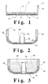
- Figure 1 shows an electrode assembly for an air depolarised cell, containing an air distribution membrane 4, a hydrophobic layer 3, and an electrode 8 disposed on the base 10 of a can 2.
- circular can 2 contains an air distribution membrane 4 secured to the inner surface of the can 2.
- a hydrophobic layer 3, for example of polytetrafluoroethylene, covers the entire bottom of the can 2 including the air distribution membrane 4.
- the can 2 has patterned internal embossed sections 6 (optional) to provide a defined gap for uniform air distribution across the surface of the electrode 8.
- the can 2 comprises base 10 abutting a peripheral upstanding wall 12, and disposed in base 10 is an opening 14 providing an air-entry port.
- Figures 2 and 3 show a gasket 18 with a peripheral upstanding wall 20, a base segment 24 and an internal upstanding wall 26 defining an opening 28.
- a cylindrical current collector 30 is secured within opening 28.
- a groove 32 is disposed in the wall segment 20 of gasket 18.
- a cup 34 having a peripheral flange 36 is disposed in groove 32 and is in physical contact with current collector 30 so that cup 34 functions as a terminal for the cell.
- the gasket 18 is shown with a negative electrode mixture 38 placed in the gasket and making electronic contact with the cup 34 via current collector 30.
- the current collector 30 is a wire or nail 30A that is electrically secured at one end to a cup 34A.
- cup 34B is shown as a simple sheet of conductive material folded to produce a central protruding conductive segment 30B that functions as the current collector.
- the can 2 along with the inserted electrode assembly is inverted over the gasket 18 which is preassembled and contains negative electrode 38.
- the flange 36 of the cup 34 is disposed within groove 32 of gasket 18 and the cup 34 rests on the current collector 30.
- the edge or rim 40 of the can 2 is crimped inwardly.
- the rim 40 of the can 2 is compressed against the electrically insulating gasket 18 which is located between the cup 34 and the can 2, thereby forming a seal and an electrical barrier between the can 2 and the cup 34.
Abstract
Description
Claims (17)
- A miniature galvanic cell comprising a two-part conductive housing sealed by an insulating gasket, one housing part being a cup associated with one of the electrodes and the other housing part being a can associated with the other electrode, wherein the gasket extends over the internal surface of at least one housing part to form an insulating layer between the housing part and its associated electrode, a current collector extends from the housing part into its associated electrode through an opening in the insulating layer, and the can is secured to the gasket to provide a seal for the cell.
- A galvanic cell according to claim 1, wherein the gasket extends over the internal surface of at least the cup, and the current collector is in electrical contact with the cup.
- A galvanic cell according to claim 2, wherein the gasket further extends over a portion of the current collector.
- A galvanic cell according to claim 2, wherein the cup and the current collector are a unitary member.
- A galvanic cell according to claim 2, wherein the cup and the current collector are two members.
- A galvanic cell according to claim 5, wherein the current collector is a wire, a nail or a cylinder member.
- A galvanic cell according to any of claims 1 to 6, wherein the gasket is made of a unitary material.
- A galvanic cell according to any of claims 1 to 6, wherein the gasket is made of at least two separate segments.
- A galvanic cell according to any preceding claim, wherein the gasket is made of a material selected from synthetic rubber, vinylidene fluoride resin, polyamide resin, polyolefin, polyvinyl chloride, silicone, polypropylene and tetrafluoroethylene polymer.
- A galvanic cell according to any preceding claim, wherein the surface area of the current collector disposed within the electrode is less than 25%, preferably less than 10%, more preferably less than 7%, of the gasket's internal surface area.
- A galvanic cell according to any preceding claim, wherein the cell is an air depolarised cell, preferably a zinc-air cell.
- A galvanic cell according to claim 1, comprising:a) a first electrode having a polarity;b) a second electrode of opposite polarity;c) a separator between the first electrode and the second electrode;d) an electrolyte;e) a two-part conductive housing containing the first electrode, the second electrode, the separator and the electrolyte, the first part of the housing being a conductive can having a wall with an edge defining an opening and being electrically connected to one of the electrodes, and the second part of the housing being a conductive cup having a peripheral flange and being electrically connected to the other electrode;f) a gasket comprising a base segment, an inner wall defining an opening in the base segment, and a peripheral wall; wherein the peripheral wall of the gasket is disposed adjacent the wall of the can, and the edge of the can is sealed against the gasket thereby securing the can to the gasket to provide a seal for the cell; andg) a current collector member extending through the opening in the base segment of the gasket and electrically contacting one electrode at one end and electrically contacting the cup at the other end.
- A galvanic cell according to claim 12, wherein the peripheral wall of the gasket has an annular groove therein, and the flange of the cup is secured in the groove.
- A galvanic cell according to claim 13, wherein the flange of the cup forms a curved segment on the wall of the cup that is secured in the groove, and the depth of the groove is at least the length of the curved segment.
- A galvanic cell according to any of claims 12 to 14, wherein the peripheral wall, inner wall, and base segment define an internal surface area for the gasket, and the current collector has a surface area disposed within the second electrode of less than 25% of the gasket's internal surface area.
- A gasket as defined in any of claims 12 to 15, for a miniature cell.
- A process for assembling the components of a miniature cell into a two-part conductive housing in which one part is a cup and the other part is a can comprising the steps:(a) preparing a conductive can with a peripheral wall terminating with an edge defining an opening;(b) preparing a gasket having a base segment, a peripheral wall having a groove therein, and an inner wall defining an opening;(c) preparing a conductive cup with a peripheral flange;(d) placing a current collector within and through the opening in the gasket, placing the flange of the cup within the groove, and securing the cup to the gasket so that the flange is secured within the groove of the gasket;(e) placing the components of the cell, comprising at least two electrodes and an electrolyte, within the can and cup so that the wall of the can is in parallel alignment with the peripheral wall of the gasket; and(f) securing the wall of the can against the wall of the gasket to produce a sealed cell.
Applications Claiming Priority (3)
| Application Number | Priority Date | Filing Date | Title |
|---|---|---|---|
| US08/970,683 US6051337A (en) | 1997-11-14 | 1997-11-14 | Miniature galvanic cell having optimum low surface area conductive collector |
| US970683 | 1997-11-14 | ||
| PCT/US1998/024115 WO1999026302A1 (en) | 1997-11-14 | 1998-11-12 | Miniature galvanic cell having optimum low surface area conductive collector |
Publications (2)
| Publication Number | Publication Date |
|---|---|
| EP1029376A1 EP1029376A1 (en) | 2000-08-23 |
| EP1029376B1 true EP1029376B1 (en) | 2001-10-10 |
Family
ID=25517320
Family Applications (1)
| Application Number | Title | Priority Date | Filing Date |
|---|---|---|---|
| EP98957851A Expired - Lifetime EP1029376B1 (en) | 1997-11-14 | 1998-11-12 | Miniature galvanic cell having optimum low surface area conductive collector |
Country Status (10)
| Country | Link |
|---|---|
| US (1) | US6051337A (en) |
| EP (1) | EP1029376B1 (en) |
| JP (1) | JP4354635B2 (en) |
| CN (1) | CN1151564C (en) |
| AT (1) | ATE206845T1 (en) |
| AU (1) | AU1401099A (en) |
| CA (1) | CA2309495A1 (en) |
| DE (1) | DE69802004T2 (en) |
| TW (1) | TW402823B (en) |
| WO (1) | WO1999026302A1 (en) |
Families Citing this family (6)
| Publication number | Priority date | Publication date | Assignee | Title |
|---|---|---|---|---|
| US6051337A (en) * | 1997-11-14 | 2000-04-18 | Eveready Battery Company, Inc. | Miniature galvanic cell having optimum low surface area conductive collector |
| CN1321469C (en) * | 2004-03-04 | 2007-06-13 | 松下电器产业株式会社 | Square gas battery |
| US7816026B2 (en) * | 2006-09-22 | 2010-10-19 | Eveready Battery Company, Inc. | Battery having air electrode and biased lever gasket |
| JP6045830B2 (en) * | 2012-07-13 | 2016-12-14 | 日立マクセル株式会社 | Flat battery |
| US20150118545A1 (en) * | 2012-07-13 | 2015-04-30 | Hitachi Maxell, Ltd. | Flat battery |
| JP6045848B2 (en) * | 2012-08-13 | 2016-12-14 | 日立マクセル株式会社 | Flat battery |
Family Cites Families (12)
| Publication number | Priority date | Publication date | Assignee | Title |
|---|---|---|---|---|
| DE152235C (en) * | ||||
| FI750695A (en) * | 1975-03-11 | 1976-09-12 | Imatra Paristo Oy | |
| US4041211A (en) * | 1975-10-06 | 1977-08-09 | Unican Electrochemical Products Ltd. | Production of zinc-air button cell |
| US4302517A (en) * | 1980-06-26 | 1981-11-24 | Union Carbide Corporation | Unitary seal and cover support gasket for miniature button cells |
| US4885217A (en) * | 1987-07-06 | 1989-12-05 | Alupower, Inc. | Air cathodes and materials therefor |
| DE4413808B4 (en) * | 1993-04-27 | 2007-06-06 | Medtronic, Inc., Minneapolis | Method for producing an assembly for an electrochemical cell, method for assembling an electrochemical cell and button cell |
| DE4325628C2 (en) * | 1993-07-30 | 2002-12-05 | Stross Gmbh & Co Besitzgesells | Gas-tight sealed, galvanic button cell |
| US5618640A (en) * | 1993-10-22 | 1997-04-08 | Fuji Photo Film Co., Ltd. | Nonaqueous secondary battery |
| DE69602122T2 (en) * | 1995-03-07 | 1999-08-19 | Matsushita Electric Ind Co Ltd | Flat cell |
| US5662717A (en) * | 1995-05-05 | 1997-09-02 | Rayovac Corporation | Metal-air cathode can having reduced corner radius and electrochemical cells made therewith |
| JPH09199187A (en) * | 1996-01-16 | 1997-07-31 | Matsushita Electric Ind Co Ltd | Button type air-zinc battery |
| US6051337A (en) * | 1997-11-14 | 2000-04-18 | Eveready Battery Company, Inc. | Miniature galvanic cell having optimum low surface area conductive collector |
-
1997
- 1997-11-14 US US08/970,683 patent/US6051337A/en not_active Expired - Lifetime
-
1998
- 1998-11-09 TW TW087118604A patent/TW402823B/en not_active IP Right Cessation
- 1998-11-12 DE DE69802004T patent/DE69802004T2/en not_active Expired - Lifetime
- 1998-11-12 EP EP98957851A patent/EP1029376B1/en not_active Expired - Lifetime
- 1998-11-12 WO PCT/US1998/024115 patent/WO1999026302A1/en active IP Right Grant
- 1998-11-12 AU AU14010/99A patent/AU1401099A/en not_active Abandoned
- 1998-11-12 AT AT98957851T patent/ATE206845T1/en not_active IP Right Cessation
- 1998-11-12 JP JP2000521560A patent/JP4354635B2/en not_active Expired - Fee Related
- 1998-11-12 CA CA002309495A patent/CA2309495A1/en not_active Abandoned
- 1998-11-12 CN CNB988130319A patent/CN1151564C/en not_active Expired - Fee Related
Also Published As
| Publication number | Publication date |
|---|---|
| JP2001523885A (en) | 2001-11-27 |
| WO1999026302A1 (en) | 1999-05-27 |
| CA2309495A1 (en) | 1999-05-27 |
| CN1151564C (en) | 2004-05-26 |
| AU1401099A (en) | 1999-06-07 |
| ATE206845T1 (en) | 2001-10-15 |
| US6051337A (en) | 2000-04-18 |
| JP4354635B2 (en) | 2009-10-28 |
| EP1029376A1 (en) | 2000-08-23 |
| CN1285957A (en) | 2001-02-28 |
| DE69802004T2 (en) | 2002-05-29 |
| DE69802004D1 (en) | 2001-11-15 |
| TW402823B (en) | 2000-08-21 |
Similar Documents
| Publication | Publication Date | Title |
|---|---|---|
| US5843597A (en) | Ribbed gasket for miniature galvanic cell | |
| US4343869A (en) | Seal for metal-air batteries | |
| EP0068183B1 (en) | Sealed electrochemical cell | |
| US5712058A (en) | Miniature galvanic cell having optimum internal volume for the active components | |
| US5846672A (en) | Indented electrode cup for a miniature galvanic cell | |
| US5641367A (en) | Process for ultrasonic sealing an anode cup into a gasket for electrochemical cells | |
| EP1029376B1 (en) | Miniature galvanic cell having optimum low surface area conductive collector | |
| US6183902B1 (en) | Beaded electrode cup for a miniature galvanic cell | |
| EP0089496B1 (en) | Galvanic cell construction and method for its assembly | |
| JP2001102025A (en) | Enclosed electric cell | |
| US6033799A (en) | Miniature galvanic cell having optimum internal volume for the active components | |
| US7442467B2 (en) | Sealed battery | |
| KR100875105B1 (en) | Cylindrical Pneumatic Zinc Battery and Manufacturing Method Thereof | |
| US9966643B2 (en) | Battery cell having air electrode assembly bonded to can and method of manufacture | |
| JP2002093456A (en) | Battery | |
| JPH08241699A (en) | Button type alkaline battery |
Legal Events
| Date | Code | Title | Description |
|---|---|---|---|
| PUAI | Public reference made under article 153(3) epc to a published international application that has entered the european phase |
Free format text: ORIGINAL CODE: 0009012 |
|
| 17P | Request for examination filed |
Effective date: 20000515 |
|
| AK | Designated contracting states |
Kind code of ref document: A1 Designated state(s): AT BE CH CY DE DK ES FI FR GB GR IE IT LI LU MC NL PT SE |
|
| GRAG | Despatch of communication of intention to grant |
Free format text: ORIGINAL CODE: EPIDOS AGRA |
|
| 17Q | First examination report despatched |
Effective date: 20001129 |
|
| GRAG | Despatch of communication of intention to grant |
Free format text: ORIGINAL CODE: EPIDOS AGRA |
|
| GRAH | Despatch of communication of intention to grant a patent |
Free format text: ORIGINAL CODE: EPIDOS IGRA |
|
| GRAH | Despatch of communication of intention to grant a patent |
Free format text: ORIGINAL CODE: EPIDOS IGRA |
|
| GRAA | (expected) grant |
Free format text: ORIGINAL CODE: 0009210 |
|
| AK | Designated contracting states |
Kind code of ref document: B1 Designated state(s): AT BE CH CY DE DK ES FI FR GB GR IE IT LI LU MC NL PT SE |
|
| PG25 | Lapsed in a contracting state [announced via postgrant information from national office to epo] |
Ref country code: NL Free format text: LAPSE BECAUSE OF FAILURE TO SUBMIT A TRANSLATION OF THE DESCRIPTION OR TO PAY THE FEE WITHIN THE PRESCRIBED TIME-LIMIT Effective date: 20011010 Ref country code: IT Free format text: LAPSE BECAUSE OF FAILURE TO SUBMIT A TRANSLATION OF THE DESCRIPTION OR TO PAY THE FEE WITHIN THE PRE;WARNING: LAPSES OF ITALIAN PATENTS WITH EFFECTIVE DATE BEFORE 2007 MAY HAVE OCCURRED AT ANY TIME BEFORE 2007. THE CORRECT EFFECTIVE DATE MAY BE DIFFERENT FROM THE ONE RECORDED.SCRIBED TIME-LIMIT Effective date: 20011010 Ref country code: FR Free format text: LAPSE BECAUSE OF FAILURE TO SUBMIT A TRANSLATION OF THE DESCRIPTION OR TO PAY THE FEE WITHIN THE PRESCRIBED TIME-LIMIT Effective date: 20011010 Ref country code: FI Free format text: LAPSE BECAUSE OF FAILURE TO SUBMIT A TRANSLATION OF THE DESCRIPTION OR TO PAY THE FEE WITHIN THE PRESCRIBED TIME-LIMIT Effective date: 20011010 Ref country code: CY Free format text: LAPSE BECAUSE OF NON-PAYMENT OF DUE FEES Effective date: 20011010 Ref country code: AT Free format text: LAPSE BECAUSE OF FAILURE TO SUBMIT A TRANSLATION OF THE DESCRIPTION OR TO PAY THE FEE WITHIN THE PRESCRIBED TIME-LIMIT Effective date: 20011010 |
|
| REF | Corresponds to: |
Ref document number: 206845 Country of ref document: AT Date of ref document: 20011015 Kind code of ref document: T |
|
| REG | Reference to a national code |
Ref country code: CH Ref legal event code: EP |
|
| PG25 | Lapsed in a contracting state [announced via postgrant information from national office to epo] |
Ref country code: MC Free format text: LAPSE BECAUSE OF NON-PAYMENT OF DUE FEES Effective date: 20011112 Ref country code: LU Free format text: LAPSE BECAUSE OF NON-PAYMENT OF DUE FEES Effective date: 20011112 Ref country code: IE Free format text: LAPSE BECAUSE OF FAILURE TO SUBMIT A TRANSLATION OF THE DESCRIPTION OR TO PAY THE FEE WITHIN THE PRESCRIBED TIME-LIMIT Effective date: 20011112 |
|
| REG | Reference to a national code |
Ref country code: IE Ref legal event code: FG4D |
|
| REF | Corresponds to: |
Ref document number: 69802004 Country of ref document: DE Date of ref document: 20011115 |
|
| REG | Reference to a national code |
Ref country code: CH Ref legal event code: NV Representative=s name: RITSCHER & SEIFERT |
|
| REG | Reference to a national code |
Ref country code: GB Ref legal event code: IF02 |
|
| PG25 | Lapsed in a contracting state [announced via postgrant information from national office to epo] |
Ref country code: SE Free format text: LAPSE BECAUSE OF FAILURE TO SUBMIT A TRANSLATION OF THE DESCRIPTION OR TO PAY THE FEE WITHIN THE PRESCRIBED TIME-LIMIT Effective date: 20020110 Ref country code: PT Free format text: LAPSE BECAUSE OF FAILURE TO SUBMIT A TRANSLATION OF THE DESCRIPTION OR TO PAY THE FEE WITHIN THE PRESCRIBED TIME-LIMIT Effective date: 20020110 Ref country code: DK Free format text: LAPSE BECAUSE OF FAILURE TO SUBMIT A TRANSLATION OF THE DESCRIPTION OR TO PAY THE FEE WITHIN THE PRESCRIBED TIME-LIMIT Effective date: 20020110 |
|
| PG25 | Lapsed in a contracting state [announced via postgrant information from national office to epo] |
Ref country code: GR Free format text: LAPSE BECAUSE OF FAILURE TO SUBMIT A TRANSLATION OF THE DESCRIPTION OR TO PAY THE FEE WITHIN THE PRESCRIBED TIME-LIMIT Effective date: 20020111 |
|
| NLV1 | Nl: lapsed or annulled due to failure to fulfill the requirements of art. 29p and 29m of the patents act | ||
| PG25 | Lapsed in a contracting state [announced via postgrant information from national office to epo] |
Ref country code: ES Free format text: LAPSE BECAUSE OF FAILURE TO SUBMIT A TRANSLATION OF THE DESCRIPTION OR TO PAY THE FEE WITHIN THE PRESCRIBED TIME-LIMIT Effective date: 20020430 |
|
| EN | Fr: translation not filed | ||
| PLBE | No opposition filed within time limit |
Free format text: ORIGINAL CODE: 0009261 |
|
| STAA | Information on the status of an ep patent application or granted ep patent |
Free format text: STATUS: NO OPPOSITION FILED WITHIN TIME LIMIT |
|
| REG | Reference to a national code |
Ref country code: IE Ref legal event code: MM4A |
|
| 26N | No opposition filed | ||
| REG | Reference to a national code |
Ref country code: HK Ref legal event code: WD Ref document number: 1026518 Country of ref document: HK |
|
| REG | Reference to a national code |
Ref country code: CH Ref legal event code: PCAR Free format text: NEW ADDRESS: PESTALOZZISTRASSE 2 POSTFACH 1416, 8201 SCHAFFHAUSEN (CH) |
|
| PGFP | Annual fee paid to national office [announced via postgrant information from national office to epo] |
Ref country code: CH Payment date: 20131127 Year of fee payment: 16 |
|
| PGFP | Annual fee paid to national office [announced via postgrant information from national office to epo] |
Ref country code: GB Payment date: 20141127 Year of fee payment: 17 Ref country code: DE Payment date: 20141128 Year of fee payment: 17 |
|
| PGFP | Annual fee paid to national office [announced via postgrant information from national office to epo] |
Ref country code: BE Payment date: 20141128 Year of fee payment: 17 |
|
| REG | Reference to a national code |
Ref country code: CH Ref legal event code: PL |
|
| PG25 | Lapsed in a contracting state [announced via postgrant information from national office to epo] |
Ref country code: CH Free format text: LAPSE BECAUSE OF NON-PAYMENT OF DUE FEES Effective date: 20141130 Ref country code: LI Free format text: LAPSE BECAUSE OF NON-PAYMENT OF DUE FEES Effective date: 20141130 |
|
| REG | Reference to a national code |
Ref country code: DE Ref legal event code: R119 Ref document number: 69802004 Country of ref document: DE |
|
| GBPC | Gb: european patent ceased through non-payment of renewal fee |
Effective date: 20151112 |
|
| PG25 | Lapsed in a contracting state [announced via postgrant information from national office to epo] |
Ref country code: DE Free format text: LAPSE BECAUSE OF NON-PAYMENT OF DUE FEES Effective date: 20160601 Ref country code: GB Free format text: LAPSE BECAUSE OF NON-PAYMENT OF DUE FEES Effective date: 20151112 |
|
| PG25 | Lapsed in a contracting state [announced via postgrant information from national office to epo] |
Ref country code: BE Free format text: LAPSE BECAUSE OF NON-PAYMENT OF DUE FEES Effective date: 20151130 |