EP1028566A2 - Distortion estimation apparatus, frequency offset compensation apparatus and reception apparatus for QAM signals - Google Patents
Distortion estimation apparatus, frequency offset compensation apparatus and reception apparatus for QAM signals Download PDFInfo
- Publication number
- EP1028566A2 EP1028566A2 EP00102770A EP00102770A EP1028566A2 EP 1028566 A2 EP1028566 A2 EP 1028566A2 EP 00102770 A EP00102770 A EP 00102770A EP 00102770 A EP00102770 A EP 00102770A EP 1028566 A2 EP1028566 A2 EP 1028566A2
- Authority
- EP
- European Patent Office
- Prior art keywords
- frequency offset
- amount
- variation amount
- phase
- symbol
- Prior art date
- Legal status (The legal status is an assumption and is not a legal conclusion. Google has not performed a legal analysis and makes no representation as to the accuracy of the status listed.)
- Withdrawn
Links
Images







Classifications
-
- H—ELECTRICITY
- H04—ELECTRIC COMMUNICATION TECHNIQUE
- H04L—TRANSMISSION OF DIGITAL INFORMATION, e.g. TELEGRAPHIC COMMUNICATION
- H04L27/00—Modulated-carrier systems
- H04L27/32—Carrier systems characterised by combinations of two or more of the types covered by groups H04L27/02, H04L27/10, H04L27/18 or H04L27/26
- H04L27/34—Amplitude- and phase-modulated carrier systems, e.g. quadrature-amplitude modulated carrier systems
- H04L27/38—Demodulator circuits; Receiver circuits
- H04L27/3809—Amplitude regulation arrangements
-
- H—ELECTRICITY
- H04—ELECTRIC COMMUNICATION TECHNIQUE
- H04L—TRANSMISSION OF DIGITAL INFORMATION, e.g. TELEGRAPHIC COMMUNICATION
- H04L27/00—Modulated-carrier systems
- H04L27/32—Carrier systems characterised by combinations of two or more of the types covered by groups H04L27/02, H04L27/10, H04L27/18 or H04L27/26
- H04L27/34—Amplitude- and phase-modulated carrier systems, e.g. quadrature-amplitude modulated carrier systems
- H04L27/38—Demodulator circuits; Receiver circuits
- H04L27/3845—Demodulator circuits; Receiver circuits using non - coherent demodulation, i.e. not using a phase synchronous carrier
- H04L27/3854—Demodulator circuits; Receiver circuits using non - coherent demodulation, i.e. not using a phase synchronous carrier using a non - coherent carrier, including systems with baseband correction for phase or frequency offset
- H04L27/3872—Compensation for phase rotation in the demodulated signal
Definitions
- the present invention relates to a distortion estimation apparatus, frequency offset compensation apparatus, reception apparatus and their method used in a radio communication apparatus.
- spectral efficiency In radio communications for which the demand has been increased rapidly in recent years, the improvement of spectral efficiency is required.
- One of effective technologies for improving the spectral efficiency is a QAM (Quadrature Amplitude Modulation).
- This method relates a system in which a transmission side transmits transmission data with a frame structure comprised of the predetermined number of symbols with a pilot symbol, known between the transmission and reception sides, inserted between data symbol sequences periodically, and the reception side detects a signal space position of the pilot symbol, and estimates a fading distortion amount of each symbol from the relationship between the relative position of each point to compensate.
- This method uses the characteristic of the radio communication that the scale and gradient of a signal space diagram varies depending on an amplitude variation and phase variation of the transmission signal generated under the rayleigh fading environment, however the entire shape of the signal space diagram does not vary.
- FIG.1 is a block diagram illustrating a configuration of a conventional distortion compensation apparatus.
- the distortion compensation apparatus in FIG.1 is mainly comprised of clock reproduction section 11, pilot detection section 12, pilot symbol extraction section 13, distortion amount calculation section 14, data symbol extraction section 15, data delay section 16 and distortion estimation compensation section 17.
- a received complex baseband signal u (t) is inputted to clock reproduction section 11, pilot detection section 12, pilot symbol extraction section 13, and data symbol extraction section 15.
- Clock reproduction section 11 controls a clock signal oscillated from an internal oscillator based on the received complex baseband signal u (t), and outputs the controlled clock signal to pilot detection section 12 and data symbol extraction section 15.
- Pilot detection section 12 detects a position of the pilot symbol in the received complex baseband signal u (t) based on the clock signal, and outputs a signal indicative of the position of the pilot symbol to pilot symbol extraction section 13.
- Pilot symbol extraction section 13 extracts the pilot symbol from the received complex baseband signal u (t) at the same timing when a signal is inputted from pilot detection section 12, and outputs the extracted pilot symbol to distortion amount calculation section 14.
- a fading distortion amount c p of the pilot symbol can be obtained with the equation (2) shown below.
- Distortion amount calculation section 14 calculates fading distortion amount c p of the pilot symbol with the above equation (2) to output to distortion estimation compensation section 17.
- Data symbol extraction section 15 extracts a data symbol from the received complex baseband signal u (t) based on the clock signal to output to data delay section 16.
- Data delay section 16 delays the inputted data symbol by a time required in distortion estimation compensation section 17 for estimating the fading distortion amount of the data symbol to output to fading distortion estimation compensation section 17.
- Distortion estimation compensation section 17 interpolates the fading distortion amount of the data symbol on the time axis based on fading distortion amount c p of the pilot symbol to estimate. Then, distortion estimation compensation section 17 multiplies the data symbol by a reciprocal (complex conjugate) of the fading distortion amount of the data symbol to compensate the fading distortion of the data symbol.
- FIG.2 is a diagram showing a relationship between time (abscissa) and distortion amount of each symbol (ordinate). As illustrated in FIG.2, approximate polynomial 21 is determined based on the fading distortion amount of the pilot symbol ( ⁇ ) , and fading distortion amount of each data symbol ( ⁇ ) is placed on approximate polynomial 21. In addition, FIG.2 adopts the frame structure in which the pilot symbol is inserted periodically every 8 symbols.
- the above-described conventional distortion apparatus performs the interpolation based on the fading distortion amount of the pilot symbol, and thereby estimates the fading distortion amount of the data symbol to compensate.
- a first object of the present invention is to estimate a frequency offset and fading distortion with high accuracy even in the case where the frequency offset between a transmitter and receiver is large, and to suppress the deterioration of the bit error rate characteristic.
- the above object of the present invention is achieved by calculating an amplitude variation amount of data symbol and phase variation mount of the data symbol separately, or estimating a fading distortion of the data symbol using the pilot symbol subjected to frequency offset compensation.
- a second object of the present invention is to obtain excellent bit error rate characteristic even in the case where the fading variation is large, and a signal with low received field strength is received.
- the above object of the present invention is achieved by judging whether or not the pilot symbol was detected effectively, and calculating the frequency offset using only the effectively detected pilot symbol.
- FIG.4 is a block diagram illustrating a configuration of a reception apparatus according to the first embodiment of the present invention.
- the reception apparatus illustrated in FIG.4 is mainly comprised of antenna 101, reception radio section 102, timing detection section 103, distortion estimation section 104 according to the first embodiment, and detection section 105.
- a signal received at antenna 101 is inputted to reception radio section 102.
- Reception radio section 102 executes quadrature demodulation on the inputted signal, and outputs an in-phase component and quadrature component of a received quadrature baseband signal to timing detection section 103, distortion estimation apparatus 104 and detection section 105.
- Timing detection section 103 acquires frame-symbol synchronization based on the in-phase component and quadrature component of the received quadrature baseband signal, and outputs a timing signal indicative of a head of a frame-symbol to distortion estimation apparatus 104 and detection section 105.
- Distortion estimation apparatus 104 receives the inputted in-phase component and quadrature component of the received quadrature baseband signal and timing signal, estimates an amplitude variation amount and phase variation amount as described later, and outputs the estimated results to detection section 105.
- Detection section 105 executes detection processing on the in-phase component and quadrature component of the received quadrature baseband signal using the amplitude variation amount and phase variation amount, and outputs a digital signal.
- a method for using the amplitude variation amount and phase variation amount for example, there are a method for varying a threshold for use in judgment in the detection processing based on the amplitude variation amount and phase variation amount, and another method for multiplying the in-phase component and quadrature component of the received quadrature baseband signal by inverse properties of the amplitude variation amount and phase variation amount.
- FIG.5 is a block diagram illustrating an internal configuration of a distortion estimation apparatus according to this embodiment.
- Distortion estimation apparatus 104 illustrated in FIG.5 is mainly comprised of in-phase component approximation section 111, quadrature component approximation section 112, amplitude variation calculation section 113, and phase variation calculation section 114.
- in-phase component approximation section 111 outputs a signal indicative of amplitude variation amount r k of the in-phase component of the data symbol calculated with the above equation (3) to amplitude variation calculation section 113.
- quadrature component approximation section 112 outputs a signal indicative of amplitude variation amount s k of the quadrature component of the data symbol calculated with the above equation (4) to amplitude variation calculation section 113.
- Phase variation calculation section 114 receives the inputted in-phase component and quadrature component of the received quadrature baseband signal and timing signal, and calculates the phase variation amount of the data symbol based on the phase variation amount of the pilot symbol approximately.
- ⁇ k k 8 tan -1 ( Q i I i ) + (1 - k 8 ) tan -1 ( Q i-1 I i-1 ) ⁇
- phase variation amount ⁇ k calculated with the above equation (6) is a value including a phase variation amount caused by the fading and another phase variation amount caused by the frequency offset.
- phase variation calculation section 114 outputs a signal indicative of phase variation amount ⁇ k of the data symbol calculated with the above equation (6) to detection section 105.
- FIG.6 is a block diagram illustrating a configuration of a reception apparatus according to the second embodiment of the present invention.
- the components having the function common to that in the reception apparatus illustrated in FIG.4 are given the same symbols as in FIG.4, and the explanations thereof are omitted.
- the reception apparatus in FIG.6 adopts a configuration in which frequency offset compensation apparatus 200 is added to the reception apparatus in FIG.4.
- the functions of distortion estimation apparatus 202 and detection section 203 are different from those of distortion estimation apparatus 104 and detection section 105 of the reception apparatus in FIG.4.
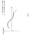
- FIG.7 is a diagram illustrating a time change of a phase of a pilot symbol on the complex plane.
- m is a natural number
- N is an insertion interval of a pilot symbol
- T is a symbol period
- each pilot symbol P0, P1, P2, ⁇ , Pm-1, Pm, Pm+1 ⁇
- Frequency offset compensation apparatus 201 receives the inputted in-phase component and quadrature component of the received quadrature baseband signal and timing signal, and extracts the pilot symbol. Then, frequency offset compensation apparatus 201 calculates the phase variation amount between the pilot symbols to calculate the frequency offset amount, and compensates the frequency offset of the pilot symbol by inversely rotating the phase of the pilot symbol by the calculated frequency offset amount.
- frequency offset compensation apparatus 201 outputs the in-phase component and quadrature component of the pilot symbol subjected to the frequency offset compensation to distortion estimation apparatus 202, and further outputs the estimated frequency offset amount to detection section 203.
- frequency offset compensation apparatus 201 outputs the in-phase component and quadrature component of the pilot symbol subjected to the frequency offset compensation to distortion estimation apparatus 202, and further outputs the estimated frequency offset amount to detection section 203.
- the detailed internal configuration of frequency offset compensation apparatus 201 is described later.
- Distortion estimation apparatus 202 receives the inputted in-phase component and quadrature component of the received quadrature baseband signal and timing signal, estimates the amplitude variation amounts of the in-phase component and quadrature component of the pilot symbol as described later, and outputs the estimated results to detection section 203.
- Detection section 203 executes detection processing on the in-phase component and quadrature component of the received quadrature baseband signal using the frequency offset amount and the amplitude variation amount of the pilot symbol, and outputs a digital signal.
- a method for using the frequency offset amount and the amplitude variation amount of the pilot symbol for example, there are a method for varying a threshold for use in judgment in the detection processing based on the frequency offset amount and the amplitude variation amount of the pilot symbol, and another method for multiplying the in-phase component and quadrature component of the received quadrature baseband signal by inverse properties of the frequency offset amount and the amplitude variation amount of the pilot symbol.
- frequency offset compensation apparatus 201 of the distortion estimation apparatus is next explained using a block diagram in FIG.8.
- Frequency offset compensation apparatus 201 is mainly comprised of phase variation amount calculation section 211, memory section 212, frequency offset calculation section 213, and frequency offset removing section 214.
- Phase variation amount calculation section 211 receives the inputted in-phase component and quadrature component of the received quadrature baseband signal and timing signal, extracts the pilot symbol, and obtains phase variation amount ⁇ i between the pilot symbols from in-phase component I i of pilot symbol i, in-phase component I i-1 of pilot symbol i-1, quadrature component Q i of pilot symbol i and quadrature component Q i-1 of pilot symbol i-1 with the equation (7) shown below. Then, phase variation amount calculation section 211 outputs a signal indicative of phase variation amount ⁇ i to memory section 212 and frequency offset calculation section 213.
- ⁇ k k 8 tan -1 ( Q i I i ) + (1 - k 8 ) tan -1 ( Q i-1 I i-1 ) ⁇
- Memory section 212 holds the inputted phase variation amount ⁇ i , and according to the timing signal, outputs phase variation amount ⁇ i-1 already held.
- Frequency offset calculation section 213 calculates the frequency offset amount using, for example, phase variation amount ⁇ i and phase variation amount ⁇ i-1 , and outputs a signal indicative of the frequency offset amount to detection section 203 and frequency offset removing section 214.
- the frequency offset amount is generally obtained by averaging a plurality of phase variation amounts obtained previously.
- Frequency offset removing section 214 receives the inputted in-phase component and quadrature component of the received quadrature baseband signal, timing signal and the signal indicative of the frequency offset amount, extracts the pilot symbol, removes the frequency offset amount from the in-phase component and quadrature component of the pilot symbol to compensate, and outputs the in-phase component and quadrature component of the pilot symbol subjected to the frequency offset compensation to distortion estimation apparatus 202.
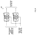
- Distortion estimation apparatus 202 is mainly comprised of in-phase component approximation section 221, and quadrature component approximation section 222.
- In-phase component approximation section 221 receives the inputted in-phase component of the pilot symbol subjected to the frequency offset compensation and timing signal, and calculates the fading distortion amount of the in-phase component of the data symbol approximately.
- r k k ⁇ I i 8 + (1 - k 8 ) ⁇ I i-1 ⁇
- in-phase component approximation section 221 outputs a signal indicative of fading distortion amount r k of the in-phase component of the data symbol calculated to detection section 203.
- Quadrature component approximation section 222 receives the inputted quadrature component of the pilot symbol subjected to the frequency offset compensation and timing signal, and calculates the fading distortion amount of the quadrature component of the data symbol approximately.
- s k k ⁇ Q i 8 + (1 - k 8 ) ⁇ Q i-1 ⁇
- quadrature component approximation section 222 outputs a signal indicative of fading distortion amount s k of the quadrature component of the data symbol calculated to detection section 203.
- the third embodiment of the present invention is obtained to solve the above problem, and in this embodiment, excellent bit error rate characteristic can be obtained even in the case where the fading variation is large, and a signal with low field strength is received.
- FIG.11 is a block diagram illustrating a configuration of a reception apparatus according to the third embodiment of the present invention.
- the components having the function common to that in the reception apparatus illustrated in FIG.6 are given the same symbols as in FIG.6, and the explanations thereof are omitted.
- the functions of frequency offset compensation apparatus 301 and detection section 302 are different from those of frequency offset compensation apparatus 201 and detection section 203 of the reception apparatus illustrated in FIG.6.
- the reception apparatus in FIG.11 adopts a configuration in which distortion estimation apparatus 202 is eliminated as compared the reception apparatus illustrated in FIG.6.
- Frequency offset compensation apparatus 301 receives the inputted in-phase component and quadrature component of the received quadrature baseband signal and timing signal, and extracts the pilot symbol. Then, frequency offset compensation apparatus 301 judges whether or not the pilot symbol was detected effectively, calculates a frequency offset amount using only the effectively detected pilot symbol, and compensates the frequency offset amount of the pilot symbol by inversely rotating the phase of the received quadrature baseband signal by the calculated frequency offset amount.
- frequency offset compensation apparatus 301 outputs the in-phase component and quadrature component of the pilot symbol subjected to the frequency offset compensation and estimated frequency offset amount to detection section 302.
- Detection section 302 executes detection processing on the in-phase component and quadrature component of the received quadrature baseband signal using the frequency offset amount, and outputs a digital signal.
- a method for using the frequency offset amount for example, there are a method for varying a threshold for use in judgment in the detection processing based on the frequency offset amount, and another method for multiplying the in-phase component and quadrature component of the received quadrature baseband signal by an inverse property of the frequency offset amount.
- FIG.12 is a block diagram illustrating an internal configuration of frequency offset compensation apparatus 301.
- the function of frequency offset amount calculation section 311 is different from that of frequency offset amount calculation section 213 in frequency offset compensation apparatus 201 illustrated in FIG.8.
- frequency offset compensation apparatus 301 in FIG.12 adopts a configuration in which correlation value calculation section 312 is added as compared to frequency offset compensation apparatus 201 illustrated in FIG.8.
- Correlation value calculation section 312 receives phase variation amount ⁇ i inputted from phase variation calculation amount section 211 and phase variation amount ⁇ i-1 inputted from memory section 212, and calculates the correlation value indicative of the correlation between phase variation amount ⁇ i and phase variation amount ⁇ i-1 (for example, an absolute value of a value obtained by subtracting phase variation amount ⁇ i-1 from phase variation amount ⁇ i ) to output to frequency offset amount calculation section 311.
- frequency offset amount calculation section 311 judges whether or not there is the correlation between phase variation amount ⁇ i and phase variation amount ⁇ i-1, in other words, whether or not pilot symbol i was effectively detected. For example, in the case where the correlation value is equal to or less than a predetermined threshold, it is judged that there is the correlation between phase variation amount ⁇ i and phase variation amount ⁇ i-i, and that pilot symbol i was effectively detected.
- frequency offset amount calculation section 311 calculates the frequency offset amount using phase variation amount ⁇ i when judges that there is the correlation between phase variation amount ⁇ i and phase variation amount ⁇ i-1, while calculating the frequency offset amount without using phase variation amount ⁇ i when judges that there is not the correlation between phase variation amount ⁇ i and phase variation amount ⁇ i-1.
- frequency offset amount calculation section 311 outputs a signal indicative of a judgement result on whether or not there is the correlation between phase variation amount ⁇ i and phase variation amount ⁇ i-1 (hereinafter referred to as "correlation result signal") to an external apparatus such as a CPU not shown in the figure.
- correlation result signal a signal indicative of a judgement result on whether or not there is the correlation between phase variation amount ⁇ i and phase variation amount ⁇ i-1
- the external apparatus may perform an judgement of data effectiveness and judgment of channel switch such as diversity and handover.
- correlation value calculation section 312 outputs a signal indicative of the correlation value between phase variation amount ⁇ i and phase variation amount ⁇ i-1 (hereinafter referred to as "correlation value signal") to detection section 203, and that detection section 203 judges whether or not there is the correlation between phase variation amount ⁇ i and phase variation amount ⁇ i-1.
- correlation value calculation section 312 outputs the correlation value signal to an external apparatus such as a CPU not shown in the figure, and that the external apparatus such as the CPU judges whether or not there is the correlation between phase variation amount ⁇ i and phase variation amount ⁇ i-1, and based on the judgement result, performs an judgement of data effectiveness and judgment of channel switch such as diversity and handover.
- phase variation amount calculation section 211, memory section 212 and correlation value calculation section 312 function as the control apparatus to calculate the correlation value.
- the fourth embodiment of the present invention is obtained by combining the second embodiment and third embodiment, and in this embodiment in the case where a reception apparatus has a frequency offset compensation apparatus and distortion estimation apparatus installed therein, excellent bit error rate characteristic can be obtained even in the case where a fading variation is large, and a signal with low field strength is received.
- FIG.13 is a block diagram illustrating a configuration of a reception apparatus according to the fourth embodiment of the present invention.
- the components having the function common to that in the reception apparatus illustrated in FIG.6 are given the same symbols as in FIG.6, and the explanations thereof are omitted.
- the reception apparatus in FIG.13 has frequency offset compensation apparatus 301 illustrated in FIG.11 installed therein, instead of frequency offset compensation apparatus 201, as compared to the reception apparatus illustrated in FIG.6.
- Frequency offset compensation apparatus 301 receives the inputted in-phase component and quadrature component of the received quadrature baseband signal and timing signal, and extracts the pilot symbol. Then, frequency offset compensation apparatus 301 judges whether or not the pilot symbol was detected effectively, calculates a frequency offset amount using only the effectively detected pilot symbol, and compensates the frequency offset amount of the pilot symbol by inversely rotating the phase of the received quadrature baseband signal by the calculated frequency offset amount.
- frequency offset compensation apparatus 301 outputs the in-phase component and quadrature component of the pilot symbol subjected to the frequency offset compensation to distortion estimation apparatus 202, and further outputs the estimated frequency offset amount to detection section 203.
- Detection section 203 executes detection processing on the in-phase component and quadrature component of the received quadrature baseband signal using the frequency offset amount and the amplitude variation amount of the pilot symbol, and outputs a digital signal.
- FIG.14 is a block diagram illustrating a configuration of a reception apparatus according to the fifth embodiment of the present invention.
- the components having the function common to that in the reception apparatus illustrated in FIG.6 are given the same symbols as in FIG.6, and the explanations thereof are omitted.
- frequency offset compensation apparatus 401 In the reception apparatus in FIG.14, the functions of frequency offset compensation apparatus 401, distortion estimation apparatus 402 and detection section 403 are different from those of frequency offset compensation apparatus 201, distortion estimation apparatus 202 and detection section 203 of the reception apparatus illustrated in FIG.6.
- Frequency offset compensation apparatus 401 receives the inputted in-phase component and quadrature component of the received quadrature baseband signal and timing signal, and extracts the pilot symbol. Then, frequency offset compensation apparatus 401 calculates the frequency offset amount of the pilot symbol, and estimates the frequency offset amount between data symbols by the interpolation. Then, frequency offset compensation apparatus 401 compensates the frequency offset of the received quadrature baseband signal by inversely rotating the phase of the received quadrature baseband signal by the calculated or estimated frequency offset amount.
- frequency offset compensation apparatus 401 outputs the in-phase component and quadrature component of the received quadrature baseband signal subjected to the frequency offset compensation to distortion estimation apparatus 402 and detection section 403.
- the detailed external configuration of frequency offset compensation apparatus 401 is described later.
- Distortion estimation apparatus 402 receives the inputted in-phase component and quadrature component of the received quadrature baseband signal subjected to the frequency offset compensation and timing signal, estimates amplitude variation amounts of the in-phase component and quadrature component of the received quadrature baseband signal as described later, and outputs the estimated results to detection section 403.
- Detection section 403 executes detection processing on the in-phase component and quadrature component of the received quadrature baseband signal subjected to the frequency offset compensation using the amplitude variation amounts of the in-phase component and quadrature component of the received quadrature baseband signal, and outputs a digital signal.
- frequency offset compensation apparatus 401 of the distortion estimation apparatus is next explained using a block diagram in FIG.15.
- the components having the function common to that in the frequency offset compensation apparatus 201 illustrated in FIG.8 are given the same symbols as in FIG.8, and the explanations thereof are omitted.
- frequency offset compensation apparatus 401 In frequency offset compensation apparatus 401, the functions of frequency offset amount calculation section 411 and frequency offset removing section 412 are different form those of frequency offset amount calculation section 213 and frequency offset removing section 214 in frequency offset compensation apparatus 201 illustrated in FIG.8.
- Frequency offset amount calculation section 411 calculates a frequency offset amount using, for example, phase variation amount ⁇ i and phase variation amount ⁇ i-1 , estimates the frequency offset amount between data symbols by the interpolation. Then, frequency offset amount calculation section 411 outputs a signal indicative of the frequency offset amount to frequency offset removing section 412. In addition, the frequency offset amount is generally obtained by averaging a plurality of phase variation amounts between pilot symbols obtained previously.
- Frequency offset removing section 412 receives the inputted in-phase component and quadrature component of the received quadrature baseband signal, timing signal and the signal indicative of the frequency offset amount, and based on the frequency offset amount, removes the frequency offset amount from the in-phase component and quadrature component of received quadrature baseband signal to compensate. Frequency offset removing section 412 further outputs the in-phase component and quadrature component of the received quadrature baseband signal subjected to the frequency offset compensation to distortion estimation apparatus 402.
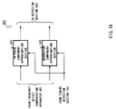
- Distortion estimation apparatus 402 is mainly comprised of in-phase component approximation section 421, and quadrature component approximation section 422.
- in-phase component approximation section 421 outputs a signal indicative of fading distortion amount r k of the in-phase component of the data symbol calculated to detection section 403.
- quadrature component approximation section 422 outputs a signal indicative of fading distortion amount s k of the quadrature component of the data symbol calculated to detection section 403.
- bit error rate characteristic can be obtained even in the case where a fading variation is large, and a signal with low field strength is received.
- FIG.17 is a block diagram illustrating a configuration of a reception apparatus according to the sixth embodiment of the present invention.
- the components having the function common to that in the reception apparatus illustrated in FIG.14 are given the same symbols as in FIG.14, and the explanations thereof are omitted.
- the functions of frequency offset compensation apparatus 501 and detection section 502 are different from those of frequency offset compensation apparatus 401 and detection section 403 of the reception apparatus illustrated in FIG.14. Further, the reception apparatus in FIG.17 has a configuration in which distortion estimation apparatus 402 is eliminated as compared to the reception apparatus illustrated in FIG.14.
- Frequency offset compensation apparatus 501 receives the inputted in-phase component and quadrature component of the received quadrature baseband signal and timing signal, and extracts the pilot symbol. Then, frequency offset compensation apparatus 501 judges whether or not the pilot symbol was detected effectively, calculates a frequency offset amount using only the effectively detected pilot symbol, and compensates the frequency offset amount between data symbols by the interpolation. Then, the frequency offset compensation apparatus 501 compensates the frequency offset amount of the received quadrature baseband signal by inversely rotating the phase of the received quadrature baseband signal by the calculated or estimated frequency offset amount.
- frequency offset compensation apparatus 501 outputs the in-phase component and quadrature component of the received quadrature baseband signal subjected to the frequency offset compensation to detection section 502.
- FIG.18 is a block diagram illustrating an internal configuration of frequency offset compensation apparatus 501.
- the function of frequency offset amount calculation section 511 is different from that of frequency offset calculation amount section 411 in frequency offset compensation apparatus 401 illustrated in FIG.15.
- frequency offset compensation apparatus 501 in FIG.18 adopts a configuration in which correlation value calculation section 512 is added as compared to frequency offset compensation apparatus 401 illustrated in FIG.15.
- Correlation value calculation section 512 receives phase variation amount ⁇ i inputted from phase variation amount calculation section 211 and phase variation amount ⁇ i-1 inputted from memory section 212, and calculates the correlation value indicative of the correlation between phase variation amount ⁇ i and phase variation amount ⁇ i-1 to output to frequency offset amount calculation section 511.
- frequency offset amount calculation section 511 judges whether or not there is the correlation between phase variation amount ⁇ i and phase variation amount ⁇ i-1, in other words, whether or not pilot symbol i was effectively detected.
- frequency offset amount calculation section 511 calculates the frequency offset amount using phase variation amount ⁇ i when judges that there is the correlation between phase variation amount ⁇ i and phase variation amount ⁇ i-1, while calculating the frequency offset amount without using phase variation amount ⁇ i when judges that there is not the correlation between phase variation amount ⁇ i and phase variation amount ⁇ i-1.
- frequency offset amount calculation section 511 outputs the correlation result signal to an external apparatus such as a CPU not shown in the figure in the same way as in frequency offset amount calculation section 511.
- correlation value calculation section 512 outputs the correlation value signal to detection section 502, and that detection section 502 judges whether or not there is the correlation between phase variation amount ⁇ i and phase variation amount ⁇ i-1 in the same way as in correlation value calculation section 312.
- correlation value calculation section 512 outputs the correlation value signal to an external apparatus such as a CPU not shown in the figure, and that the external apparatus such as the CPU judges whether or not there is the correlation between phase variation amount ⁇ i and phase variation amount ⁇ i-1, and based on the judgement result, performs an judgement of data effectiveness and judgment of channel switch such as diversity and handover, in the same way as in correlation value calculation section 312.
- phase variation amount calculation section 211, memory section 212 and correlation value calculation section 512 function as the control apparatus to calculate the correlation value.
- the seventh embodiment of the present invention is obtained by combining the fifth embodiment and sixth embodiment, and in this embodiment in the case where a reception apparatus has a frequency offset compensation apparatus and distortion estimation apparatus installed therein, excellent bit error rate characteristic can be obtained even in the case where a fading variation is large, and a signal with low field strength is received.
- FIG.19 is a block diagram illustrating a configuration of a reception apparatus according to the seventh embodiment of the present invention.
- the components having the function common to that in the reception apparatus illustrated in FIG.14 are given the same symbols as in FIG.14, and the explanations thereof are omitted.
- the reception apparatus in FIG.19 has frequency offset compensation apparatus 501 illustrated in FIG.17 installed therein, instead of frequency offset compensation apparatus 401, as compared to the reception apparatus illustrated in FIG.14.
- Frequency offset compensation apparatus 501 receives the inputted in-phase component and quadrature component of the received quadrature baseband signal and timing signal, and extracts the pilot symbol. Then, frequency offset compensation apparatus 501 judges whether or not the pilot symbol was detected effectively, calculates the frequency offset amount using only the effectively detected pilot symbol, and estimates the frequency offset amount between data symbols by the interpolation. Then, frequency offset compensation apparatus 501 compensates the frequency offset amount of the received quadrature baseband signal by inversely rotating the phase of the received quadrature baseband signal by the calculated or estimated frequency offset amount.
- frequency offset compensation apparatus 501 outputs the in-phase component and quadrature component of the received quadrature baseband signal subjected to the frequency offset compensation to distortion estimation apparatus 402 and detection section 403.
- Distortion estimation apparatus 402 receives the inputted in-phase component and quadrature component of the received quadrature baseband signal subjected to the frequency offset compensation and timing signal, estimates amplitude variation amounts of the in-phase component and quadrature component of the received quadrature baseband signal, and outputs the estimated results to detection section 403.
- Detection section 403 executes detection processing on the in-phase component and quadrature component of the received quadrature baseband signal subjected to the frequency offset compensation using the amplitude variation amounts of the in-phase component and quadrature component of the received quadrature baseband signal, and outputs a digital signal.
- the explanation is performed using the single carrier system as the communication system in each embodiment described above.
- the communication system is not limited, and it may be possible, in the case where an orthogonal frequency division multiplexing system is used, to estimate the frequency offset and fading distortion with high accuracy in demodulating a signal with each subcarrier, and to suppress the deterioration of bit error rate characteristic due to the frequency offset between a transmitter and receiver and fading distortion.
- the present invention is not limited in frame structure of a received signal, and is achieved in other cases besides that illustrated in FIG.3. Further, although each embodiment described above explains about the case where the first-order Gaussian polynomial approximation is used as a polynomial approximation, the present invention is not limited to the above case, and the same effects may be obtained using other approximation systems such as least square method.
Landscapes
- Engineering & Computer Science (AREA)
- Computer Networks & Wireless Communication (AREA)
- Signal Processing (AREA)
- Digital Transmission Methods That Use Modulated Carrier Waves (AREA)
Abstract
In-phase component approximation section 111
calculates an amplitude variation amount of an in-phase
component of a data symbol from an amplitude variation
amount of an in-phase component of a pilot symbol
approximately. Quadrature component approximation
section 112 calculates an amplitude variation amount of
a quadrature component of the data symbol from an
amplitude variation amount of a quadrature component of
the pilot symbol approximately. Amplitude variation
calculation section 113 calculates an amplitude
variation amount of each data symbol from the amplitude
variation amounts of the in-phase component and
quadrature component of each data symbol. Phase
variation calculation section 114 calculates a phase
variation amount of the data symbol from a phase variation
amount of the pilot symbol approximately. Thus, by
calculating the amplitude variation amount of the data
symbol and the phase variation amount of the data symbol
separately, even in the case where a frequency offset
between a transmitter and receiver is large, it is
possible to estimate the frequency offset and fading
distortion with high accuracy, and to suppress the
deterioration of bit error rate characteristic.
Description
- The present invention relates to a distortion estimation apparatus, frequency offset compensation apparatus, reception apparatus and their method used in a radio communication apparatus.
- In radio communications for which the demand has been increased rapidly in recent years, the improvement of spectral efficiency is required. One of effective technologies for improving the spectral efficiency is a QAM (Quadrature Amplitude Modulation).
- In order to apply the QAM to the radio communication, it is necessary to compensate a fading distortion of a transmission signal generated under the Rayleigh fading environment.
- As a method, conventionally known, for compensating such a fading distortion, there is, for example, "Rayleigh Fading Compensation Method for 16QAM MODEM in Digital Land Mobile Radio Systems" (SAMPEI, Technical Report of IEICE B-II, Vol.J-72-B-II, No.1, pp.7-15, January, 1989).
- This method relates a system in which a transmission side transmits transmission data with a frame structure comprised of the predetermined number of symbols with a pilot symbol, known between the transmission and reception sides, inserted between data symbol sequences periodically, and the reception side detects a signal space position of the pilot symbol, and estimates a fading distortion amount of each symbol from the relationship between the relative position of each point to compensate.
- This method uses the characteristic of the radio communication that the scale and gradient of a signal space diagram varies depending on an amplitude variation and phase variation of the transmission signal generated under the rayleigh fading environment, however the entire shape of the signal space diagram does not vary.
- An example of conventional technologies using this system is explained below using accompanying drawings.
- FIG.1 is a block diagram illustrating a configuration of a conventional distortion compensation apparatus.
- The distortion compensation apparatus in FIG.1 is mainly comprised of
clock reproduction section 11, pilot detection section 12, pilotsymbol extraction section 13, distortion amount calculation section 14, datasymbol extraction section 15,data delay section 16 and distortion estimation compensation section 17. - In the distortion compensation apparatus in FIG.1, a received complex baseband signal u (t) is inputted to
clock reproduction section 11, pilot detection section 12, pilotsymbol extraction section 13, and datasymbol extraction section 15. -
Clock reproduction section 11 controls a clock signal oscillated from an internal oscillator based on the received complex baseband signal u (t), and outputs the controlled clock signal to pilot detection section 12 and datasymbol extraction section 15. - Pilot detection section 12 detects a position of the pilot symbol in the received complex baseband signal u (t) based on the clock signal, and outputs a signal indicative of the position of the pilot symbol to pilot
symbol extraction section 13. - Pilot
symbol extraction section 13 extracts the pilot symbol from the received complex baseband signal u (t) at the same timing when a signal is inputted from pilot detection section 12, and outputs the extracted pilot symbol to distortion amount calculation section 14. - Herein, when it is assumed that a transmission complex baseband signal is z(t), and that a fading distortion is c(t), the received complex baseband signal u (t) can be expressed with the equation (1) shown below.
- Further, when it is assumed that a received pilot symbol is up, and that a transmission pilot symbol is tp, a fading distortion amount cp of the pilot symbol can be obtained with the equation (2) shown below.
- Distortion amount calculation section 14 calculates fading distortion amount cp of the pilot symbol with the above equation (2) to output to distortion estimation compensation section 17.
- Data
symbol extraction section 15 extracts a data symbol from the received complex baseband signal u (t) based on the clock signal to output todata delay section 16. -
Data delay section 16 delays the inputted data symbol by a time required in distortion estimation compensation section 17 for estimating the fading distortion amount of the data symbol to output to fading distortion estimation compensation section 17. - Distortion estimation compensation section 17 interpolates the fading distortion amount of the data symbol on the time axis based on fading distortion amount cp of the pilot symbol to estimate. Then, distortion estimation compensation section 17 multiplies the data symbol by a reciprocal (complex conjugate) of the fading distortion amount of the data symbol to compensate the fading distortion of the data symbol.
- FIG.2 is a diagram showing a relationship between time (abscissa) and distortion amount of each symbol (ordinate). As illustrated in FIG.2,
approximate polynomial 21 is determined based on the fading distortion amount of the pilot symbol (○) , and fading distortion amount of each data symbol () is placed onapproximate polynomial 21. In addition, FIG.2 adopts the frame structure in which the pilot symbol is inserted periodically every 8 symbols. - Thus, the above-described conventional distortion apparatus performs the interpolation based on the fading distortion amount of the pilot symbol, and thereby estimates the fading distortion amount of the data symbol to compensate.
- As the causes of the distortion generated in the transmission signal in radio communications, there is a frequency offset between a transmitter and receiver besides the fading.
- However, in the above-described conventional distortion compensation apparatus, since the frequency offset is not considered, the estimation accuracy lowers in the case where the frequency offset is large, resulting in the problem that the bit error rate characteristic deteriorates.
- A first object of the present invention is to estimate a frequency offset and fading distortion with high accuracy even in the case where the frequency offset between a transmitter and receiver is large, and to suppress the deterioration of the bit error rate characteristic.
- The above object of the present invention is achieved by calculating an amplitude variation amount of data symbol and phase variation mount of the data symbol separately, or estimating a fading distortion of the data symbol using the pilot symbol subjected to frequency offset compensation.
- Further, a second object of the present invention is to obtain excellent bit error rate characteristic even in the case where the fading variation is large, and a signal with low received field strength is received.
- The above object of the present invention is achieved by judging whether or not the pilot symbol was detected effectively, and calculating the frequency offset using only the effectively detected pilot symbol.
- The above and other objects and features of the invention will appear more fully hereinafter from a consideration of the following description taken in connection with the accompanying drawing wherein one example is illustrated by way of example, in which;
- FIG.1 is a block diagram illustrating a configuration of a conventional distortion compensation apparatus;
- FIG.2 is a diagram illustrating a concept of an interpolation to perform a conventional distortion compensation;
- FIG.3 is a diagram illustrating a frame structure of a received signal received at a reception apparatus according to each embodiment of the present invention;
- FIG.4 is a block diagram illustrating a configuration of a reception apparatus according to a first embodiment of the present invention;
- FIG.5 is a block diagram illustrating a configuration of a distortion estimation apparatus according to the first embodiment of the present invention;
- FIG.6 is a block diagram illustrating a configuration of a reception apparatus according to a second embodiment of the present invention;
- FIG.7 is a conceptual diagram illustrating a time change of a phase of a pilot symbol in a frequency offset compensation;
- FIG.8 is a diagram illustrating a configuration of a frequency offset compensation apparatus according to a second embodiment;
- FIG.9 is a block diagram illustrating a configuration of a distortion estimation apparatus according to the second embodiment of the present invention;
- FIG.10 is a conceptual diagram illustrating a relationship between received power and an estimated error of a phase variation amount;
- FIG.11 is a block diagram illustrating a configuration of a reception apparatus according to a third embodiment of the present invention;
- FIG.12 is a diagram illustrating a configuration of a frequency offset compensation apparatus according to the third embodiment;
- FIG.13 is a block diagram illustrating a configuration of a reception apparatus according to a fourth embodiment of the present invention;
- FIG.14 is a block diagram illustrating a configuration of a reception apparatus according to a fifth embodiment of the present invention;
- FIG.15 is a diagram illustrating a configuration of a frequency offset compensation apparatus according to the fifth embodiment;
- FIG.16 is a block diagram illustrating a configuration of a distortion estimation apparatus according to a fifth embodiment of the present invention;
- FIG.17 is a diagram illustrating a configuration of a reception apparatus according to a sixth embodiment;
- FIG.18 is a block diagram illustrating a configuration of a frequency offset compensation apparatus according to the sixth embodiment of the present invention; and
- FIG.19 is a block diagram illustrating a configuration of a reception apparatus according to a seventh embodiment of the present invention.
-
- Embodiments of the present invention will be described specifically below with reference to drawings. In addition, in the following explanation, a single carrier system is used as a communication system. Further, in the following explanation, it is assumed that as illustrated in FIG.3, in the frame structure of a received signal, 1 block has 8 symbols, and the first 1 symbol of each block is a pilot symbol. Furthermore, it is assumed that as a polynomial approximation for use in an interpolation, the first-order Gaussian polynomial approximation is used.
- FIG.4 is a block diagram illustrating a configuration of a reception apparatus according to the first embodiment of the present invention. The reception apparatus illustrated in FIG.4 is mainly comprised of
antenna 101,reception radio section 102,timing detection section 103,distortion estimation section 104 according to the first embodiment, anddetection section 105. - In the reception apparatus illustrated in FIG.4, a signal received at
antenna 101 is inputted toreception radio section 102.Reception radio section 102 executes quadrature demodulation on the inputted signal, and outputs an in-phase component and quadrature component of a received quadrature baseband signal to timingdetection section 103,distortion estimation apparatus 104 anddetection section 105. -
Timing detection section 103 acquires frame-symbol synchronization based on the in-phase component and quadrature component of the received quadrature baseband signal, and outputs a timing signal indicative of a head of a frame-symbol todistortion estimation apparatus 104 anddetection section 105. -
Distortion estimation apparatus 104 receives the inputted in-phase component and quadrature component of the received quadrature baseband signal and timing signal, estimates an amplitude variation amount and phase variation amount as described later, and outputs the estimated results todetection section 105. -
Detection section 105 executes detection processing on the in-phase component and quadrature component of the received quadrature baseband signal using the amplitude variation amount and phase variation amount, and outputs a digital signal. In addition, as a method for using the amplitude variation amount and phase variation amount, for example, there are a method for varying a threshold for use in judgment in the detection processing based on the amplitude variation amount and phase variation amount, and another method for multiplying the in-phase component and quadrature component of the received quadrature baseband signal by inverse properties of the amplitude variation amount and phase variation amount. - FIG.5 is a block diagram illustrating an internal configuration of a distortion estimation apparatus according to this embodiment.
Distortion estimation apparatus 104 illustrated in FIG.5 is mainly comprised of in-phasecomponent approximation section 111, quadraturecomponent approximation section 112, amplitudevariation calculation section 113, and phasevariation calculation section 114. - In-phase
component approximation section 111 receives the inputted in-phase component of the received quadrature baseband signal and timing signal, and calculates the amplitude variation amount of the in-phase component of the data symbol from that of the in-phase component of the pilot symbol approximately. For example, in FIG.3, amplitude variation amount rk of the in-phase component of data symbol k (k=1 to 7) of block j is calculated from in-phase component Ii of pilot symbol i and in-phase component Ii-1 of pilot symbol i-1 with the equation (3) shown below. - Then, in-phase
component approximation section 111 outputs a signal indicative of amplitude variation amount rk of the in-phase component of the data symbol calculated with the above equation (3) to amplitudevariation calculation section 113. - Quadrature
component approximation section 112 receives the inputted quadrature component of the received quadrature baseband signal and timing signal, and calculates the amplitude variation amount of the quadrature component of the data symbol from that of the quadrature component of the pilot symbol approximately. For example, in FIG.3, amplitude variation amount sk of the quadrature component of data symbol k (k=1 to 7) of block j is calculated from quadrature component Qi of pilot symbol i and quadrature component Qi-1 of pilot symbol i-1 with the equation (4) shown below. - Then, quadrature
component approximation section 112 outputs a signal indicative of amplitude variation amount sk of the quadrature component of the data symbol calculated with the above equation (4) to amplitudevariation calculation section 113. - Amplitude
variation calculation section 113 calculates the amplitude variation amount of each data symbol from the amplitude variation amounts of the in-phase component and quadrature component of each data symbol. For example, in FIG.3, amplitude variation amount Ak of data symbol k (k=1 to 7) of block j is calculated using amplitude variation amount rk of the in-phase component and amplitude variation amount sk of the quadrature component with the equation (5) shown below.variation calculation section 113 outputs a signal indicative of the amplitude variation amount of the data symbol calculated with the above equation (5) todetection section 105. - Phase
variation calculation section 114 receives the inputted in-phase component and quadrature component of the received quadrature baseband signal and timing signal, and calculates the phase variation amount of the data symbol based on the phase variation amount of the pilot symbol approximately. For example, in FIG.3, phase variation amount k of the data symbol k (k=1 to 7) of block j is calculated from in-phase component Ii of pilot symbol i, in-phase component Ii-1 of pilot symbol i-1, quadrature component Qi of pilot symbol i and quadrature component Qi-1 of pilot symbol i-1 with the equation (6) shown below. - In addition, phase variation amount k calculated with the above equation (6) is a value including a phase variation amount caused by the fading and another phase variation amount caused by the frequency offset.
- Then, phase
variation calculation section 114 outputs a signal indicative of phase variation amount k of the data symbol calculated with the above equation (6) todetection section 105. - Thus, by calculating the amplitude variation amount of the data symbol and the phase variation amount of the data symbol separately, it is possible to estimate the frequency offset between a transmitter and receiver and the fading distortion both with high accuracy.
- Then, as illustrated in FIG.4, by installing the above-described distortion estimation apparatus in a reception apparatus, since it is possible to estimate the frequency offset between a transmitter and receiver and the fading distortion both with high accuracy to detect, it is possible to suppress the deterioration of the bit error rate characteristic.
- FIG.6 is a block diagram illustrating a configuration of a reception apparatus according to the second embodiment of the present invention. In addition, in the reception apparatus in FIG.6, the components having the function common to that in the reception apparatus illustrated in FIG.4 are given the same symbols as in FIG.4, and the explanations thereof are omitted.
- The reception apparatus in FIG.6 adopts a configuration in which frequency offset compensation apparatus 200 is added to the reception apparatus in FIG.4. In addition, in the reception apparatus in FIG.6, the functions of
distortion estimation apparatus 202 anddetection section 203 are different from those ofdistortion estimation apparatus 104 anddetection section 105 of the reception apparatus in FIG.4. - FIG.7 is a diagram illustrating a time change of a phase of a pilot symbol on the complex plane. As illustrated in FIG.7, at time
- Frequency offset
compensation apparatus 201 receives the inputted in-phase component and quadrature component of the received quadrature baseband signal and timing signal, and extracts the pilot symbol. Then, frequency offsetcompensation apparatus 201 calculates the phase variation amount between the pilot symbols to calculate the frequency offset amount, and compensates the frequency offset of the pilot symbol by inversely rotating the phase of the pilot symbol by the calculated frequency offset amount. - Then, frequency offset
compensation apparatus 201 outputs the in-phase component and quadrature component of the pilot symbol subjected to the frequency offset compensation todistortion estimation apparatus 202, and further outputs the estimated frequency offset amount todetection section 203. In addition, the detailed internal configuration of frequency offsetcompensation apparatus 201 is described later. -
Distortion estimation apparatus 202 receives the inputted in-phase component and quadrature component of the received quadrature baseband signal and timing signal, estimates the amplitude variation amounts of the in-phase component and quadrature component of the pilot symbol as described later, and outputs the estimated results todetection section 203. -
Detection section 203 executes detection processing on the in-phase component and quadrature component of the received quadrature baseband signal using the frequency offset amount and the amplitude variation amount of the pilot symbol, and outputs a digital signal. As a method for using the frequency offset amount and the amplitude variation amount of the pilot symbol, for example, there are a method for varying a threshold for use in judgment in the detection processing based on the frequency offset amount and the amplitude variation amount of the pilot symbol, and another method for multiplying the in-phase component and quadrature component of the received quadrature baseband signal by inverse properties of the frequency offset amount and the amplitude variation amount of the pilot symbol. - The internal configuration of frequency offset
compensation apparatus 201 of the distortion estimation apparatus according to this embodiment is next explained using a block diagram in FIG.8. - Frequency offset
compensation apparatus 201 is mainly comprised of phase variationamount calculation section 211,memory section 212, frequency offset calculation section 213, and frequency offset removingsection 214. - Phase variation
amount calculation section 211 receives the inputted in-phase component and quadrature component of the received quadrature baseband signal and timing signal, extracts the pilot symbol, and obtains phase variation amount i between the pilot symbols from in-phase component Ii of pilot symbol i, in-phase component Ii-1 of pilot symbol i-1, quadrature component Qi of pilot symbol i and quadrature component Qi-1 of pilot symbol i-1 with the equation (7) shown below. Then, phase variationamount calculation section 211 outputs a signal indicative of phase variation amount i tomemory section 212 and frequency offset calculation section 213. -
Memory section 212 holds the inputted phase variation amount i, and according to the timing signal, outputs phase variation amount i-1 already held. - Frequency offset calculation section 213 calculates the frequency offset amount using, for example, phase variation amount i and phase variation amount i-1, and outputs a signal indicative of the frequency offset amount to
detection section 203 and frequency offset removingsection 214. In addition, the frequency offset amount is generally obtained by averaging a plurality of phase variation amounts obtained previously. - Frequency offset removing
section 214 receives the inputted in-phase component and quadrature component of the received quadrature baseband signal, timing signal and the signal indicative of the frequency offset amount, extracts the pilot symbol, removes the frequency offset amount from the in-phase component and quadrature component of the pilot symbol to compensate, and outputs the in-phase component and quadrature component of the pilot symbol subjected to the frequency offset compensation todistortion estimation apparatus 202. - The internal configuration of
distortion estimation apparatus 202 according to this embodiment is next explained using a block diagram in FIG.9. -
Distortion estimation apparatus 202 is mainly comprised of in-phasecomponent approximation section 221, and quadraturecomponent approximation section 222. - In-phase
component approximation section 221 receives the inputted in-phase component of the pilot symbol subjected to the frequency offset compensation and timing signal, and calculates the fading distortion amount of the in-phase component of the data symbol approximately. For example, in FIG.3 previously described, fading distortion amount rk of the in-phase component of symbol k (k=1 to 7) of block j of data symbols is calculated from in-phase component Ii of pilot symbol i and in-phase component Ii-1 of pilot symbol i-1 with the equation (8) shown below. - Then, in-phase
component approximation section 221 outputs a signal indicative of fading distortion amount rk of the in-phase component of the data symbol calculated todetection section 203. - Quadrature
component approximation section 222 receives the inputted quadrature component of the pilot symbol subjected to the frequency offset compensation and timing signal, and calculates the fading distortion amount of the quadrature component of the data symbol approximately. For example, in FIG.3, fading distortion amount sk of the quadrature component of symbol k (k=1 to 7) of block j of data symbols is calculated from quadrature component Qi of pilot symbol i and quadrature component Qi-1 of pilot symbol i-1 with the equation (9) shown below. - Then, quadrature
component approximation section 222 outputs a signal indicative of fading distortion amount sk of the quadrature component of the data symbol calculated todetection section 203. - Thus, by compensating the frequency offset of the pilot symbol, and estimating the fading distortion of the data symbol using the pilot symbol subjected to the frequency offset compensation, it is possible to estimate the frequency offset between a transmitter and receiver and the fading distortion with high accuracy.
- Then, as illustrated in FIG.6, by installing the above-described frequency offset compensation apparatus and distortion estimation apparatus in a reception apparatus, since it is possible to estimate the frequency offset between a transmitter and receiver and the fading distortion both with high accuracy to detect, it is possible to suppress the deterioration of the bit error rate characteristic.
- When the received field strength is low due to, for example, fading, the estimated error of phase variation amount becomes large because effects of noise are increased.
- For example, in FIG.10, it is assumed that signal A with high received field strength and signal B with low received field strength each moves in a range of a circle with broken lines due to the effects of noise. As can be seen from FIG.10, error b of phase rotation angle relating to signal B is larger than error a of phase rotation angle relating to signal A. Further, with respect to signal C with extremely low received field strength, by the effects of noise, the quadrant on which signal C is present changes, and therefore it is not possible to estimate the phase rotation angle correctly.
- When the frequency offset amount is estimated using a signal with low field strength, the bit error rate characteristic deteriorates because the estimated error becomes large.
- The third embodiment of the present invention is obtained to solve the above problem, and in this embodiment, excellent bit error rate characteristic can be obtained even in the case where the fading variation is large, and a signal with low field strength is received.
- FIG.11 is a block diagram illustrating a configuration of a reception apparatus according to the third embodiment of the present invention. In addition, in the reception apparatus in FIG.11, the components having the function common to that in the reception apparatus illustrated in FIG.6 are given the same symbols as in FIG.6, and the explanations thereof are omitted.
- In the reception apparatus in FIG.11, the functions of frequency offset
compensation apparatus 301 anddetection section 302 are different from those of frequency offsetcompensation apparatus 201 anddetection section 203 of the reception apparatus illustrated in FIG.6. In addition, the reception apparatus in FIG.11 adopts a configuration in whichdistortion estimation apparatus 202 is eliminated as compared the reception apparatus illustrated in FIG.6. - Frequency offset
compensation apparatus 301 receives the inputted in-phase component and quadrature component of the received quadrature baseband signal and timing signal, and extracts the pilot symbol. Then, frequency offsetcompensation apparatus 301 judges whether or not the pilot symbol was detected effectively, calculates a frequency offset amount using only the effectively detected pilot symbol, and compensates the frequency offset amount of the pilot symbol by inversely rotating the phase of the received quadrature baseband signal by the calculated frequency offset amount. - Then, frequency offset
compensation apparatus 301 outputs the in-phase component and quadrature component of the pilot symbol subjected to the frequency offset compensation and estimated frequency offset amount todetection section 302. -
Detection section 302 executes detection processing on the in-phase component and quadrature component of the received quadrature baseband signal using the frequency offset amount, and outputs a digital signal. As a method for using the frequency offset amount, for example, there are a method for varying a threshold for use in judgment in the detection processing based on the frequency offset amount, and another method for multiplying the in-phase component and quadrature component of the received quadrature baseband signal by an inverse property of the frequency offset amount. - FIG.12 is a block diagram illustrating an internal configuration of frequency offset
compensation apparatus 301. In frequency offsetcompensation apparatus 301 in FIG.12, the function of frequency offsetamount calculation section 311 is different from that of frequency offset amount calculation section 213 in frequency offsetcompensation apparatus 201 illustrated in FIG.8. Further, frequency offsetcompensation apparatus 301 in FIG.12 adopts a configuration in which correlationvalue calculation section 312 is added as compared to frequency offsetcompensation apparatus 201 illustrated in FIG.8. - Correlation
value calculation section 312 receives phase variation amount i inputted from phase variationcalculation amount section 211 and phase variation amount i-1 inputted frommemory section 212, and calculates the correlation value indicative of the correlation between phase variation amount i and phase variation amount i-1 (for example, an absolute value of a value obtained by subtracting phase variation amount i-1 from phase variation amount i) to output to frequency offsetamount calculation section 311. - Based on the correlation value, frequency offset
amount calculation section 311 judges whether or not there is the correlation between phase variation amount i and phase variation amount i-1, in other words, whether or not pilot symbol i was effectively detected. For example, in the case where the correlation value is equal to or less than a predetermined threshold, it is judged that there is the correlation between phase variation amount i and phase variation amount i-i, and that pilot symbol i was effectively detected. - Then, frequency offset
amount calculation section 311 calculates the frequency offset amount using phase variation amount i when judges that there is the correlation between phase variation amount i and phase variation amount i-1, while calculating the frequency offset amount without using phase variation amount i when judges that there is not the correlation between phase variation amount i and phase variation amount i-1. - In addition, it may be possible that frequency offset
amount calculation section 311 outputs a signal indicative of a judgement result on whether or not there is the correlation between phase variation amount i and phase variation amount i-1 (hereinafter referred to as "correlation result signal") to an external apparatus such as a CPU not shown in the figure. In this case, based on the content of the correlation result signal, the external apparatus may perform an judgement of data effectiveness and judgment of channel switch such as diversity and handover. - Further, it may be possible that correlation
value calculation section 312 outputs a signal indicative of the correlation value between phase variation amount i and phase variation amount i-1 (hereinafter referred to as "correlation value signal") todetection section 203, and thatdetection section 203 judges whether or not there is the correlation between phase variation amount i and phase variation amount i-1. - Furthermore, it may be possible that correlation
value calculation section 312 outputs the correlation value signal to an external apparatus such as a CPU not shown in the figure, and that the external apparatus such as the CPU judges whether or not there is the correlation between phase variation amount i and phase variation amount i-1, and based on the judgement result, performs an judgement of data effectiveness and judgment of channel switch such as diversity and handover. In this case, phase variationamount calculation section 211,memory section 212 and correlationvalue calculation section 312 function as the control apparatus to calculate the correlation value. - Thus, by judging whether or not the pilot symbol was detected effectively, and calculating the frequency offset amount of the pilot symbol using only the effectively detected pilot symbol, it is possible to obtain excellent bit error rate characteristic even in the case where the fading variation is large, and the signal with low received field strength is received.
- The fourth embodiment of the present invention is obtained by combining the second embodiment and third embodiment, and in this embodiment in the case where a reception apparatus has a frequency offset compensation apparatus and distortion estimation apparatus installed therein, excellent bit error rate characteristic can be obtained even in the case where a fading variation is large, and a signal with low field strength is received.
- FIG.13 is a block diagram illustrating a configuration of a reception apparatus according to the fourth embodiment of the present invention. In addition, in the reception apparatus in FIG.13, the components having the function common to that in the reception apparatus illustrated in FIG.6 are given the same symbols as in FIG.6, and the explanations thereof are omitted.
- The reception apparatus in FIG.13 has frequency offset
compensation apparatus 301 illustrated in FIG.11 installed therein, instead of frequency offsetcompensation apparatus 201, as compared to the reception apparatus illustrated in FIG.6. - Frequency offset
compensation apparatus 301 receives the inputted in-phase component and quadrature component of the received quadrature baseband signal and timing signal, and extracts the pilot symbol. Then, frequency offsetcompensation apparatus 301 judges whether or not the pilot symbol was detected effectively, calculates a frequency offset amount using only the effectively detected pilot symbol, and compensates the frequency offset amount of the pilot symbol by inversely rotating the phase of the received quadrature baseband signal by the calculated frequency offset amount. - Then, frequency offset
compensation apparatus 301 outputs the in-phase component and quadrature component of the pilot symbol subjected to the frequency offset compensation todistortion estimation apparatus 202, and further outputs the estimated frequency offset amount todetection section 203. -
Detection section 203 executes detection processing on the in-phase component and quadrature component of the received quadrature baseband signal using the frequency offset amount and the amplitude variation amount of the pilot symbol, and outputs a digital signal. - Thus, by judging whether or not the pilot symbol was detected effectively, calculating the frequency offset amount of the pilot symbol using only the effectively detected pilot symbol to compensate the frequency offset of the pilot symbol, and estimating the fading distortion of the data symbol using the pilot symbol subjected to the frequency offset compensation, it is possible to obtain excellent bit error rate characteristic even in the case where the fading variation is large, and the signal with low received field strength is received, and further to estimate the frequency offset between a transmitter and receiver and fading distortion with high accuracy.
- FIG.14 is a block diagram illustrating a configuration of a reception apparatus according to the fifth embodiment of the present invention. In addition, in the reception apparatus in FIG.14, the components having the function common to that in the reception apparatus illustrated in FIG.6 are given the same symbols as in FIG.6, and the explanations thereof are omitted.
- In the reception apparatus in FIG.14, the functions of frequency offset
compensation apparatus 401,distortion estimation apparatus 402 anddetection section 403 are different from those of frequency offsetcompensation apparatus 201,distortion estimation apparatus 202 anddetection section 203 of the reception apparatus illustrated in FIG.6. - Frequency offset
compensation apparatus 401 receives the inputted in-phase component and quadrature component of the received quadrature baseband signal and timing signal, and extracts the pilot symbol. Then, frequency offsetcompensation apparatus 401 calculates the frequency offset amount of the pilot symbol, and estimates the frequency offset amount between data symbols by the interpolation. Then, frequency offsetcompensation apparatus 401 compensates the frequency offset of the received quadrature baseband signal by inversely rotating the phase of the received quadrature baseband signal by the calculated or estimated frequency offset amount. - Then, frequency offset
compensation apparatus 401 outputs the in-phase component and quadrature component of the received quadrature baseband signal subjected to the frequency offset compensation todistortion estimation apparatus 402 anddetection section 403. In addition, the detailed external configuration of frequency offsetcompensation apparatus 401 is described later. -
Distortion estimation apparatus 402 receives the inputted in-phase component and quadrature component of the received quadrature baseband signal subjected to the frequency offset compensation and timing signal, estimates amplitude variation amounts of the in-phase component and quadrature component of the received quadrature baseband signal as described later, and outputs the estimated results todetection section 403. -
Detection section 403 executes detection processing on the in-phase component and quadrature component of the received quadrature baseband signal subjected to the frequency offset compensation using the amplitude variation amounts of the in-phase component and quadrature component of the received quadrature baseband signal, and outputs a digital signal. - The internal configuration of frequency offset
compensation apparatus 401 of the distortion estimation apparatus according to this embodiment is next explained using a block diagram in FIG.15. In addition, in frequency offsetcompensation apparatus 401 in FIG.15, the components having the function common to that in the frequency offsetcompensation apparatus 201 illustrated in FIG.8 are given the same symbols as in FIG.8, and the explanations thereof are omitted. - In frequency offset
compensation apparatus 401, the functions of frequency offsetamount calculation section 411 and frequency offset removingsection 412 are different form those of frequency offset amount calculation section 213 and frequency offset removingsection 214 in frequency offsetcompensation apparatus 201 illustrated in FIG.8. - Frequency offset
amount calculation section 411 calculates a frequency offset amount using, for example, phase variation amount i and phase variation amount i-1, estimates the frequency offset amount between data symbols by the interpolation. Then, frequency offsetamount calculation section 411 outputs a signal indicative of the frequency offset amount to frequency offset removingsection 412. In addition, the frequency offset amount is generally obtained by averaging a plurality of phase variation amounts between pilot symbols obtained previously. - Frequency offset removing
section 412 receives the inputted in-phase component and quadrature component of the received quadrature baseband signal, timing signal and the signal indicative of the frequency offset amount, and based on the frequency offset amount, removes the frequency offset amount from the in-phase component and quadrature component of received quadrature baseband signal to compensate. Frequency offset removingsection 412 further outputs the in-phase component and quadrature component of the received quadrature baseband signal subjected to the frequency offset compensation todistortion estimation apparatus 402. - The internal configuration of
distortion estimation apparatus 402 according to this embodiment is next explained using a block diagram in FIG.16. -
Distortion estimation apparatus 402 is mainly comprised of in-phasecomponent approximation section 421, and quadraturecomponent approximation section 422. - In-phase
component approximation section 421 receives the inputted in-phase component of the received quadrature baseband signal subjected to the frequency offset compensation and timing signal, extracts the pilot symbol, and calculates the fading distortion amount of the in-phase component of the data symbol approximately. For example, in FIG.3 previously described, fading distortion amount rk of the in-phase component of data symbol k (k=1 to 7) of block j is calculated with the equation (8) described previously. - Then, in-phase
component approximation section 421 outputs a signal indicative of fading distortion amount rk of the in-phase component of the data symbol calculated todetection section 403. - Quadrature
component approximation section 422 receives the inputted quadrature component of the received quadrature baseband signal subjected to the frequency offset compensation and timing signal, extracts the pilot symbol, and calculates the fading distortion amount of the quadrature component of the data symbol approximately. For example, in FIG.3, fading distortion amount sk of the quadrature component of symbol k (k=1 to 7) of block j of data symbols is calculated with the equation (9) described previously. - Then, quadrature
component approximation section 422 outputs a signal indicative of fading distortion amount sk of the quadrature component of the data symbol calculated todetection section 403. - Thus, by compensating the frequency offset of the received quadrature baseband signal, and estimating the fading distortion of the data symbol using the pilot symbol subjected to the frequency offset compensation, it is possible to estimate the frequency offset between a transmitter and receiver and the fading distortion with high accuracy.
- Then, as illustrated in FIG.14, by installing the above-described frequency offset compensation apparatus and distortion estimation apparatus in a reception apparatus, since it is possible to estimate the frequency offset between a transmitter and receiver and the fading distortion both with high accuracy to detect, it is possible to suppress the deterioration of the bit error rate characteristic.
- In the sixth embodiment of the present invention, excellent bit error rate characteristic can be obtained even in the case where a fading variation is large, and a signal with low field strength is received.
- FIG.17 is a block diagram illustrating a configuration of a reception apparatus according to the sixth embodiment of the present invention. In addition, in the reception apparatus in FIG.17, the components having the function common to that in the reception apparatus illustrated in FIG.14 are given the same symbols as in FIG.14, and the explanations thereof are omitted.
- In the reception apparatus in FIG.17, the functions of frequency offset
compensation apparatus 501 anddetection section 502 are different from those of frequency offsetcompensation apparatus 401 anddetection section 403 of the reception apparatus illustrated in FIG.14. Further, the reception apparatus in FIG.17 has a configuration in whichdistortion estimation apparatus 402 is eliminated as compared to the reception apparatus illustrated in FIG.14. - Frequency offset
compensation apparatus 501 receives the inputted in-phase component and quadrature component of the received quadrature baseband signal and timing signal, and extracts the pilot symbol. Then, frequency offsetcompensation apparatus 501 judges whether or not the pilot symbol was detected effectively, calculates a frequency offset amount using only the effectively detected pilot symbol, and compensates the frequency offset amount between data symbols by the interpolation. Then, the frequency offsetcompensation apparatus 501 compensates the frequency offset amount of the received quadrature baseband signal by inversely rotating the phase of the received quadrature baseband signal by the calculated or estimated frequency offset amount. - Then, frequency offset
compensation apparatus 501 outputs the in-phase component and quadrature component of the received quadrature baseband signal subjected to the frequency offset compensation todetection section 502. - FIG.18 is a block diagram illustrating an internal configuration of frequency offset
compensation apparatus 501. In frequency offsetcompensation apparatus 501 in FIG.18, the function of frequency offsetamount calculation section 511 is different from that of frequency offsetcalculation amount section 411 in frequency offsetcompensation apparatus 401 illustrated in FIG.15. Further, frequency offsetcompensation apparatus 501 in FIG.18 adopts a configuration in which correlationvalue calculation section 512 is added as compared to frequency offsetcompensation apparatus 401 illustrated in FIG.15. - Correlation
value calculation section 512 receives phase variation amount i inputted from phase variationamount calculation section 211 and phase variation amount i-1 inputted frommemory section 212, and calculates the correlation value indicative of the correlation between phase variation amount i and phase variation amount i-1 to output to frequency offsetamount calculation section 511. - Based on the correlation value, frequency offset
amount calculation section 511 judges whether or not there is the correlation between phase variation amount i and phase variation amount i-1, in other words, whether or not pilot symbol i was effectively detected. - Then, frequency offset
amount calculation section 511 calculates the frequency offset amount using phase variation amount i when judges that there is the correlation between phase variation amount i and phase variation amount i-1, while calculating the frequency offset amount without using phase variation amount i when judges that there is not the correlation between phase variation amount i and phase variation amount i-1. - In addition, it may be possible that frequency offset
amount calculation section 511 outputs the correlation result signal to an external apparatus such as a CPU not shown in the figure in the same way as in frequency offsetamount calculation section 511. - Further, it may be possible that correlation
value calculation section 512 outputs the correlation value signal todetection section 502, and thatdetection section 502 judges whether or not there is the correlation between phase variation amount i and phase variation amount i-1 in the same way as in correlationvalue calculation section 312. - Furthermore, it may be possible that correlation
value calculation section 512 outputs the correlation value signal to an external apparatus such as a CPU not shown in the figure, and that the external apparatus such as the CPU judges whether or not there is the correlation between phase variation amount i and phase variation amount i-1, and based on the judgement result, performs an judgement of data effectiveness and judgment of channel switch such as diversity and handover, in the same way as in correlationvalue calculation section 312. In this case, phase variationamount calculation section 211,memory section 212 and correlationvalue calculation section 512 function as the control apparatus to calculate the correlation value. - Thus, by judging whether or not the pilot symbol was detected effectively, and calculating the frequency offset amount of the received quadrature baseband signal using only the effectively detected pilot symbol, it is possible to obtain excellent bit error rate characteristic even in the case where the fading variation is large, and the signal with low received field strength is received.
- The seventh embodiment of the present invention is obtained by combining the fifth embodiment and sixth embodiment, and in this embodiment in the case where a reception apparatus has a frequency offset compensation apparatus and distortion estimation apparatus installed therein, excellent bit error rate characteristic can be obtained even in the case where a fading variation is large, and a signal with low field strength is received.
- FIG.19 is a block diagram illustrating a configuration of a reception apparatus according to the seventh embodiment of the present invention. In addition, in the reception apparatus in FIG.19, the components having the function common to that in the reception apparatus illustrated in FIG.14 are given the same symbols as in FIG.14, and the explanations thereof are omitted.
- The reception apparatus in FIG.19 has frequency offset
compensation apparatus 501 illustrated in FIG.17 installed therein, instead of frequency offsetcompensation apparatus 401, as compared to the reception apparatus illustrated in FIG.14. - Frequency offset
compensation apparatus 501 receives the inputted in-phase component and quadrature component of the received quadrature baseband signal and timing signal, and extracts the pilot symbol. Then, frequency offsetcompensation apparatus 501 judges whether or not the pilot symbol was detected effectively, calculates the frequency offset amount using only the effectively detected pilot symbol, and estimates the frequency offset amount between data symbols by the interpolation. Then, frequency offsetcompensation apparatus 501 compensates the frequency offset amount of the received quadrature baseband signal by inversely rotating the phase of the received quadrature baseband signal by the calculated or estimated frequency offset amount. - Then, frequency offset
compensation apparatus 501 outputs the in-phase component and quadrature component of the received quadrature baseband signal subjected to the frequency offset compensation todistortion estimation apparatus 402 anddetection section 403. -
Distortion estimation apparatus 402 receives the inputted in-phase component and quadrature component of the received quadrature baseband signal subjected to the frequency offset compensation and timing signal, estimates amplitude variation amounts of the in-phase component and quadrature component of the received quadrature baseband signal, and outputs the estimated results todetection section 403. -
Detection section 403 executes detection processing on the in-phase component and quadrature component of the received quadrature baseband signal subjected to the frequency offset compensation using the amplitude variation amounts of the in-phase component and quadrature component of the received quadrature baseband signal, and outputs a digital signal. - Thus, by judging whether or not the pilot symbol was detected effectively, calculating the frequency offset amount of the received quadrature baseband signal using only the effectively detected pilot symbol to compensate the frequency offset of the received quadrature baseband signal, and estimating the fading distortion of the data symbol using the pilot symbol subjected to the frequency offset compensation, it is possible to obtain excellent bit error rate characteristic even in the case where the fading variation is large, and the signal with low received field strength is received, and further to estimate the frequency offset between a transmitter and receiver and fading distortion with high accuracy.
- In addition, the explanation is performed using the single carrier system as the communication system in each embodiment described above. However, in the present invention, the communication system is not limited, and it may be possible, in the case where an orthogonal frequency division multiplexing system is used, to estimate the frequency offset and fading distortion with high accuracy in demodulating a signal with each subcarrier, and to suppress the deterioration of bit error rate characteristic due to the frequency offset between a transmitter and receiver and fading distortion.
- Further, in the case where a code division multiple access system is used, in the same way as in the single carrier system, it may be possible to estimate the frequency offset and fading distortion with high accuracy after despreading, and to suppress the deterioration of bit error rate characteristic due to the frequency offset between a transmitter and receiver and fading distortion.
- In addition, the present invention is not limited in frame structure of a received signal, and is achieved in other cases besides that illustrated in FIG.3. Further, although each embodiment described above explains about the case where the first-order Gaussian polynomial approximation is used as a polynomial approximation, the present invention is not limited to the above case, and the same effects may be obtained using other approximation systems such as least square method.
- The present invention is not limited to the above described embodiments, and various variations and modifications may be possible without departing from the scope of the present invention.
- This application is based on the Japanese Patent Applications No.HEI11-034038 filed on February 12, 1999, No.HEI11-041227 filed on February 19, 1999, and No.HEI11-044390 filed on February 23, 1999, entire contents of which are expressly incorporated by reference herein.
Claims (16)
- A distortion estimation apparatus comprising:amplitude variation amount estimator (111,112,113) for estimating an amplitude variation amount of a data symbol based on an amplitude variation amount of a known symbol; andphase variation amount estimator (114) for estimating a phase variation amount of said data symbol based on a phase variation amount of said known symbol.
- The distortion estimation apparatus according to claim 1, wherein said amplitude variation amount estimator (111,112,113) estimates the amplitude variation amount of said data symbol by an interpolation based on the amplitude variation amount of said known symbol.
- The distortion estimation apparatus according to claim 1, wherein said phase variation amount estimator (114) estimates the phase variation amount of said data symbol by an interpolation based on the phase variation amount of said known symbol.
- A reception apparatus having a distortion estimation apparatus, said distortion estimation apparatus comprising:amplitude variation amount estimator for estimating an amplitude variation amount of a data symbol based on an amplitude variation amount of a known symbol; andphase variation amount estimator for estimating a phase variation amount of said data symbol based on a phase variation amount of said known symbol.
- A control apparatus comprising:phase variation amount calculator (211) for calculating a phase variation amount of a known symbol; andcorrelation value calculator (312) for calculating a correlation value that is a difference between the phase variation amount of the known symbol received currently and the phase variation amount of the known symbol received previously.
- A frequency offset compensation apparatus comprising:correlation value calculator (211,312) for calculating a correlation value that is a difference between a phase variation amount of a known symbol received currently and the phase variation amount of the known symbol received previously;frequency offset amount calculator (213) for calculating a first frequency offset amount of said known symbol received currently using a plurality of known symbols satisfying a condition predetermined based on said correlation value; andfrequency offset remover (214) for removing a frequency offset of said known symbol received currently using said first frequency offset amount.
- The frequency offset compensation apparatus according to claim 6, wherein said frequency offset amount compensator (213) calculates said first frequency offset amount using phase variation amounts of a plurality of known symbols each with the correlation value equal to or less than a predetermined threshold.
- The frequency offset compensation apparatus according to claim 6, wherein said frequency offset remover (214) estimates a second frequency offset amount of a data symbol based on a frequency offset amount of the known symbol, and using the second frequency offset amount, removes a frequency offset of said data symbol.
- The frequency offset compensation apparatus according to claim 8, wherein said frequency offset remover (214) estimates the second frequency offset amount by an interpolation based on the frequency offset amount of the known symbol.
- A reception apparatus comprising:a frequency offset compensation apparatus (201) which removes a frequency offset of a known symbol; anda distortion estimation apparatus (202) which estimates an amplitude variation amount of a data symbol based on an amplitude variation amount of a known symbol from which the frequency offset is removed.
- The reception apparatus according to claim 10, wherein said frequency offset compensation apparatus (201) comprising:correlation value calculator (211) for calculating a correlation value that is a difference between a phase variation amount of a known symbol received currently and a phase variation amount of a known symbol received previously;frequency offset amount calculator (213) for calculating a first frequency offset amount of said known symbol received currently using a plurality of known symbols satisfying a condition predetermined based on said correlation value;frequency offset remover (214) for removing a frequency offset of said known symbol received currently using said first frequency offset amount.
- A reception apparatus comprising:a frequency offset compensation apparatus (201) which estimates a frequency offset amount of a data symbol based on a frequency offset amount of a known symbol, and removes a frequency offset of said known symbol and a frequency offset of said data symbol using said frequency offset amount; anda distortion estimation apparatus (202) which estimates an amplitude variation amount of said data symbol from which the frequency offset is removed based on the amplitude variation amount of said known symbol from which the frequency offset is removed.
- The reception apparatus according to claim 12, wherein said frequency offset compensation apparatus (201) comprising:correlation value calculator (211) for calculating a correlation value that is a difference between a phase variation amount of a known symbol received currently and a phase variation amount of a known symbol received previously;frequency offset amount calculator (213) for calculating a first frequency offset amount of said known symbol received currently using a plurality of known symbols satisfying a condition predetermined based on said correlation value;frequency offset remover (214) for removing a frequency offset of said known symbol received currently using said first frequency offset amount, estimating a second frequency offset amount of the data symbol based on the frequency offset amount of the known symbol, and removing the frequency offset of said data symbol using the second frequency offset amount.
- A distortion estimation method comprising:estimating an amplitude variation amount of a data symbol based on an amplitude variation amount of a known symbol; andestimating a phase variation amount of said data symbol based on a phase variation amount of said known symbol.
- A frequency offset compensation method comprising:calculating a correlation value that is a difference between a phase variation amount of a known symbol received currently and the phase variation amount of the known symbol received previously;calculating a first frequency offset amount of said known symbol received currently using a plurality of known symbols satisfying a condition predetermined based on said correlation value; andremoving a frequency offset of said known symbol received currently using said first frequency offset amount.
- The frequency offset compensation method according to claim 15, further comprising:estimating a second frequency offset amount of a data symbol based on a frequency offset amount of the known symbol; andremoving a frequency offset of said data symbol using the second frequency offset amount.
Applications Claiming Priority (6)
| Application Number | Priority Date | Filing Date | Title |
|---|---|---|---|
| JP3403899 | 1999-02-12 | ||
| JP3403899A JP2000236365A (en) | 1999-02-12 | 1999-02-12 | Distortion estimation device and demodulation device using the same |
| JP11041227A JP2000244598A (en) | 1999-02-19 | 1999-02-19 | Control device, frequency offset compensating device, and demodulating device using the same |
| JP4122799 | 1999-02-19 | ||
| JP11044390A JP2000244599A (en) | 1999-02-23 | 1999-02-23 | Distortion estimation device and demodulation device using the same |
| JP4439099 | 1999-02-23 |
Publications (1)
| Publication Number | Publication Date |
|---|---|
| EP1028566A2 true EP1028566A2 (en) | 2000-08-16 |
Family
ID=27288301
Family Applications (1)
| Application Number | Title | Priority Date | Filing Date |
|---|---|---|---|
| EP00102770A Withdrawn EP1028566A2 (en) | 1999-02-12 | 2000-02-10 | Distortion estimation apparatus, frequency offset compensation apparatus and reception apparatus for QAM signals |
Country Status (2)
| Country | Link |
|---|---|
| US (1) | US6748026B1 (en) |
| EP (1) | EP1028566A2 (en) |
Cited By (4)
| Publication number | Priority date | Publication date | Assignee | Title |
|---|---|---|---|---|
| WO2004023680A1 (en) | 2002-09-03 | 2004-03-18 | Stratalight Communications, Inc. | Optical receiver having compensation for kerr effect phase noise |
| KR100438447B1 (en) * | 2000-10-20 | 2004-07-03 | 삼성전자주식회사 | Burst pilot transmit apparatus and method in mobile communication system |
| EP1458088A1 (en) * | 2003-03-13 | 2004-09-15 | Samsung Electronics Co., Ltd. | Apparatus for compensating the frequency offset in a receiver, and method |
| CN108964783A (en) * | 2018-07-30 | 2018-12-07 | 中国电子科技集团公司第五十四研究所 | Coherent optical heterodyne communicatio carrier synchronization method under big Frequency Offset |
Families Citing this family (15)
| Publication number | Priority date | Publication date | Assignee | Title |
|---|---|---|---|---|
| JP3598938B2 (en) * | 2000-04-19 | 2004-12-08 | 日本電気株式会社 | Portable wireless system, portable wireless device used therefor, and frequency error estimating method used therefor |
| US7133620B1 (en) * | 2002-09-03 | 2006-11-07 | Stratalight Communication, Inc. | Optical FSK receiver having compensation for Kerr effect phase noise |
| US7130601B2 (en) * | 2002-09-13 | 2006-10-31 | Broadcom Corporation | Determination of received signal strength in a direct conversion receiver |
| US8054924B2 (en) * | 2005-05-17 | 2011-11-08 | General Motors Llc | Data transmission method with phase shift error correction |
| US8045650B2 (en) * | 2005-06-24 | 2011-10-25 | Panasonic Corporation | Radio receiving apparatus |
| US8259840B2 (en) * | 2005-10-24 | 2012-09-04 | General Motors Llc | Data communication via a voice channel of a wireless communication network using discontinuities |
| US8194779B2 (en) * | 2005-10-24 | 2012-06-05 | General Motors Llc | Method for data communication via a voice channel of a wireless communication network |
| US8194526B2 (en) * | 2005-10-24 | 2012-06-05 | General Motors Llc | Method for data communication via a voice channel of a wireless communication network |
| US7894554B2 (en) * | 2005-10-31 | 2011-02-22 | Lg Electronics Inc. | Apparatus for performing initial synchronization and frame synchronization in mobile communications system and method thereof |
| US20070190950A1 (en) * | 2006-02-15 | 2007-08-16 | General Motors Corporation | Method of configuring voice and data communication over a voice channel |
| US9048784B2 (en) * | 2007-04-03 | 2015-06-02 | General Motors Llc | Method for data communication via a voice channel of a wireless communication network using continuous signal modulation |
| US7912149B2 (en) * | 2007-05-03 | 2011-03-22 | General Motors Llc | Synchronization and segment type detection method for data transmission via an audio communication system |
| KR100876863B1 (en) * | 2007-09-18 | 2008-12-31 | 한국과학기술원 | Data reading error prevention device and method for orthogonal frequency division multiplexing symbol demodulation |
| US20160248615A1 (en) * | 2014-09-18 | 2016-08-25 | Telefonaktiebolaget L M Ericsson (Publ) | Frequency Estimation |
| EP3866375A1 (en) * | 2020-02-17 | 2021-08-18 | FRAUNHOFER-GESELLSCHAFT zur Förderung der angewandten Forschung e.V. | Packet correlator for a radio transmission system with time-varying frequency drift |
Family Cites Families (8)
| Publication number | Priority date | Publication date | Assignee | Title |
|---|---|---|---|---|
| JPH061908B2 (en) | 1988-02-02 | 1994-01-05 | 郵政省通信総合研究所長 | Transmission line distortion compensation method |
| US5590158A (en) * | 1993-01-28 | 1996-12-31 | Advantest Corporation | Method and apparatus for estimating PSK modulated signals |
| US5717722A (en) * | 1994-11-08 | 1998-02-10 | Anritsu Corporation | Precision symbol demodulation system for multi-carrier modulation signal |
| JP3013763B2 (en) * | 1995-08-25 | 2000-02-28 | 日本電気株式会社 | Carrier synchronization unit |
| JP2903104B2 (en) | 1995-09-22 | 1999-06-07 | 郵政省通信総合研究所長 | Digital mobile radio communication system |
| JPH09307526A (en) * | 1996-05-17 | 1997-11-28 | Mitsubishi Electric Corp | Digital broadcast receiver |
| CN1158786C (en) * | 1997-03-04 | 2004-07-21 | 三菱电机株式会社 | Receiver with frequency offset correction function |
| US6275685B1 (en) * | 1998-12-10 | 2001-08-14 | Nortel Networks Limited | Linear amplifier arrangement |
-
2000
- 2000-02-07 US US09/499,303 patent/US6748026B1/en not_active Expired - Fee Related
- 2000-02-10 EP EP00102770A patent/EP1028566A2/en not_active Withdrawn
Cited By (7)
| Publication number | Priority date | Publication date | Assignee | Title |
|---|---|---|---|---|
| KR100438447B1 (en) * | 2000-10-20 | 2004-07-03 | 삼성전자주식회사 | Burst pilot transmit apparatus and method in mobile communication system |
| WO2004023680A1 (en) | 2002-09-03 | 2004-03-18 | Stratalight Communications, Inc. | Optical receiver having compensation for kerr effect phase noise |
| EP1540857A4 (en) * | 2002-09-03 | 2007-04-18 | Stratalight Communications Inc | Optical receiver having compensation for kerr effect phase noise |
| EP1458088A1 (en) * | 2003-03-13 | 2004-09-15 | Samsung Electronics Co., Ltd. | Apparatus for compensating the frequency offset in a receiver, and method |
| US7103332B2 (en) | 2003-03-13 | 2006-09-05 | Samsung Electronics Co., Ltd. | Apparatus and method for compensating for frequency offset in a mobile communication system |
| CN1300947C (en) * | 2003-03-13 | 2007-02-14 | 三星电子株式会社 | Device and method for compensating frequency deviation in mobile communication system |
| CN108964783A (en) * | 2018-07-30 | 2018-12-07 | 中国电子科技集团公司第五十四研究所 | Coherent optical heterodyne communicatio carrier synchronization method under big Frequency Offset |
Also Published As
| Publication number | Publication date |
|---|---|
| US6748026B1 (en) | 2004-06-08 |
Similar Documents
| Publication | Publication Date | Title |
|---|---|---|
| US6748026B1 (en) | Distortion estimation apparatus, frequency offset compensation apparatus and reception apparatus | |
| EP1172956B1 (en) | OFDM packet communication receiver | |
| US6243423B1 (en) | Receiver, transmitter-receiver, and communication method | |
| US7463577B2 (en) | OFDM communication method and OFDM communication device | |
| EP2264934B1 (en) | Digital radio communication system and method | |
| EP0715440B1 (en) | Synchronous detector and synchronizing method for digital communication receiver | |
| US20080056305A1 (en) | Phase correction for ofdm and mimo transmissions | |
| JP4744625B2 (en) | Receiving method and receiving apparatus | |
| JP2006352746A (en) | Receiver for orthogonal frequency division multiplex transmission | |
| EP1133093A1 (en) | Ofdm communication device and detecting method | |
| US20140219222A1 (en) | Ofdm-cdma equipment and method | |
| US6546026B1 (en) | Multi-diversity synchronization technique for improving synchronization performance in wireless applications over fading channels | |
| US20030147456A1 (en) | Frequency offset estimator | |
| US7139333B2 (en) | Frequency error estimating receiver, and frequency error estimating method | |
| US5596608A (en) | Fading distortion compensation method and circuit | |
| EP0933902B1 (en) | Demodulation with fading compensation | |
| KR20070090800A (en) | Channel Estimation Apparatus and Method in Wireless Communication System | |
| EP1569401A1 (en) | Radio communication apparatus and radio communication method | |
| KR100341200B1 (en) | Quadrature frequency division multiplexing demodulator | |
| US6868056B1 (en) | Apparatus and method for OFDM communication | |
| WO1999060721A1 (en) | Method for improving signal reception in a mobile communication unit by using pilot symbols | |
| JP4285845B2 (en) | Receiver | |
| EP1233534A1 (en) | Radio receiver | |
| US7684311B2 (en) | Equalizer and equalization method | |
| JP3605638B2 (en) | Digital modulated signal equalization method and demodulator using the same |
Legal Events
| Date | Code | Title | Description |
|---|---|---|---|
| PUAI | Public reference made under article 153(3) epc to a published international application that has entered the european phase |
Free format text: ORIGINAL CODE: 0009012 |
|
| AK | Designated contracting states |
Kind code of ref document: A2 Designated state(s): AT BE CH CY DE DK ES FI FR GB GR IE IT LI LU MC NL PT SE |
|
| AX | Request for extension of the european patent |
Free format text: AL;LT;LV;MK;RO;SI |
|
| STAA | Information on the status of an ep patent application or granted ep patent |
Free format text: STATUS: THE APPLICATION HAS BEEN WITHDRAWN |
|
| 18W | Application withdrawn |
Effective date: 20060117 |