EP1028534A1 - Anzeigen der Zuverlässigkeit unkodierter Bits in einem digitalen Eingangssignal - Google Patents
Anzeigen der Zuverlässigkeit unkodierter Bits in einem digitalen Eingangssignal Download PDFInfo
- Publication number
- EP1028534A1 EP1028534A1 EP00200353A EP00200353A EP1028534A1 EP 1028534 A1 EP1028534 A1 EP 1028534A1 EP 00200353 A EP00200353 A EP 00200353A EP 00200353 A EP00200353 A EP 00200353A EP 1028534 A1 EP1028534 A1 EP 1028534A1
- Authority
- EP
- European Patent Office
- Prior art keywords
- bits
- input signal
- reliability
- symbol
- uncoded
- Prior art date
- Legal status (The legal status is an assumption and is not a legal conclusion. Google has not performed a legal analysis and makes no representation as to the accuracy of the status listed.)
- Withdrawn
Links
Images


Classifications
-
- H—ELECTRICITY
- H03—ELECTRONIC CIRCUITRY
- H03M—CODING; DECODING; CODE CONVERSION IN GENERAL
- H03M13/00—Coding, decoding or code conversion, for error detection or error correction; Coding theory basic assumptions; Coding bounds; Error probability evaluation methods; Channel models; Simulation or testing of codes
- H03M13/37—Decoding methods or techniques, not specific to the particular type of coding provided for in groups H03M13/03 - H03M13/35
- H03M13/39—Sequence estimation, i.e. using statistical methods for the reconstruction of the original codes
- H03M13/41—Sequence estimation, i.e. using statistical methods for the reconstruction of the original codes using the Viterbi algorithm or Viterbi processors
- H03M13/4138—Sequence estimation, i.e. using statistical methods for the reconstruction of the original codes using the Viterbi algorithm or Viterbi processors soft-output Viterbi algorithm based decoding, i.e. Viterbi decoding with weighted decisions
-
- H—ELECTRICITY
- H03—ELECTRONIC CIRCUITRY
- H03M—CODING; DECODING; CODE CONVERSION IN GENERAL
- H03M13/00—Coding, decoding or code conversion, for error detection or error correction; Coding theory basic assumptions; Coding bounds; Error probability evaluation methods; Channel models; Simulation or testing of codes
- H03M13/03—Error detection or forward error correction by redundancy in data representation, i.e. code words containing more digits than the source words
- H03M13/05—Error detection or forward error correction by redundancy in data representation, i.e. code words containing more digits than the source words using block codes, i.e. a predetermined number of check bits joined to a predetermined number of information bits
- H03M13/13—Linear codes
- H03M13/15—Cyclic codes, i.e. cyclic shifts of codewords produce other codewords, e.g. codes defined by a generator polynomial, Bose-Chaudhuri-Hocquenghem [BCH] codes
- H03M13/151—Cyclic codes, i.e. cyclic shifts of codewords produce other codewords, e.g. codes defined by a generator polynomial, Bose-Chaudhuri-Hocquenghem [BCH] codes using error location or error correction polynomials
- H03M13/154—Error and erasure correction, e.g. by using the error and erasure locator or Forney polynomial
-
- H—ELECTRICITY
- H03—ELECTRONIC CIRCUITRY
- H03M—CODING; DECODING; CODE CONVERSION IN GENERAL
- H03M13/00—Coding, decoding or code conversion, for error detection or error correction; Coding theory basic assumptions; Coding bounds; Error probability evaluation methods; Channel models; Simulation or testing of codes
- H03M13/25—Error detection or forward error correction by signal space coding, i.e. adding redundancy in the signal constellation, e.g. Trellis Coded Modulation [TCM]
- H03M13/256—Error detection or forward error correction by signal space coding, i.e. adding redundancy in the signal constellation, e.g. Trellis Coded Modulation [TCM] with trellis coding, e.g. with convolutional codes and TCM
-
- H—ELECTRICITY
- H03—ELECTRONIC CIRCUITRY
- H03M—CODING; DECODING; CODE CONVERSION IN GENERAL
- H03M13/00—Coding, decoding or code conversion, for error detection or error correction; Coding theory basic assumptions; Coding bounds; Error probability evaluation methods; Channel models; Simulation or testing of codes
- H03M13/29—Coding, decoding or code conversion, for error detection or error correction; Coding theory basic assumptions; Coding bounds; Error probability evaluation methods; Channel models; Simulation or testing of codes combining two or more codes or code structures, e.g. product codes, generalised product codes, concatenated codes, inner and outer codes
- H03M13/2933—Coding, decoding or code conversion, for error detection or error correction; Coding theory basic assumptions; Coding bounds; Error probability evaluation methods; Channel models; Simulation or testing of codes combining two or more codes or code structures, e.g. product codes, generalised product codes, concatenated codes, inner and outer codes using a block and a convolutional code
- H03M13/2936—Coding, decoding or code conversion, for error detection or error correction; Coding theory basic assumptions; Coding bounds; Error probability evaluation methods; Channel models; Simulation or testing of codes combining two or more codes or code structures, e.g. product codes, generalised product codes, concatenated codes, inner and outer codes using a block and a convolutional code comprising an outer Reed-Solomon code and an inner convolutional code
-
- H—ELECTRICITY
- H03—ELECTRONIC CIRCUITRY
- H03M—CODING; DECODING; CODE CONVERSION IN GENERAL
- H03M13/00—Coding, decoding or code conversion, for error detection or error correction; Coding theory basic assumptions; Coding bounds; Error probability evaluation methods; Channel models; Simulation or testing of codes
- H03M13/37—Decoding methods or techniques, not specific to the particular type of coding provided for in groups H03M13/03 - H03M13/35
- H03M13/3776—Decoding methods or techniques, not specific to the particular type of coding provided for in groups H03M13/03 - H03M13/35 using a re-encoding step during the decoding process
-
- H—ELECTRICITY
- H03—ELECTRONIC CIRCUITRY
- H03M—CODING; DECODING; CODE CONVERSION IN GENERAL
- H03M13/00—Coding, decoding or code conversion, for error detection or error correction; Coding theory basic assumptions; Coding bounds; Error probability evaluation methods; Channel models; Simulation or testing of codes
- H03M13/63—Joint error correction and other techniques
- H03M13/6337—Error control coding in combination with channel estimation
Definitions
- the present invention relates to indicating the reliability of the uncoded bits in an input signal representing digital symbols of encoded and uncoded bits.
- Conventional pragmatic trellis coded modulation and decoding provides different levels of error protection for different bits of binary data.
- 8-PSK modulation with a data rate of 2/3, for example, for every encoded (protected) bit there is one uncoded or unprotected bit.
- 8-PSK modulation where the data rate is 5/6, for every one encoded (protected) bit there are four uncoded or unprotected bits.
- the uncoded bits are less reliable in comparison with the encoded bits and it would therefore be desirable to devise ways of providing reliability estimates of the uncoded bits.
- a method of indicating the reliability of the uncoded bits in an input signal representing digital symbols of encoded and uncoded bits comprising the steps of: decoding the encoded bits to generate reference signals representing a plurality of estimates for each of the symbols, the symbol estimates being compatible with the encoded bits; comparing the input signal with the reference signals to determine the closest estimate of each symbol; and, providing indications of the reliability of the uncoded bits from the differences between the input signal and the closest symbol estimates.
- apparatus for indicating the reliability of the uncoded bits in an input signal representing digital symbols of encoded and uncoded bits
- the apparatus comprising: a decoder for decoding the encoded bits to generate reference signals representing a plurality of estimates for each of the symbols, the symbol estimates being compatible with the encoded bits; a comparator for comparing the input signal with the reference signals to determine the closest estimate of each symbol; and, means providing indications of the reliability of the uncoded bits from the differences between the input signal and the closest symbol estimates.
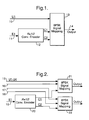
- an input bit U1 of an input symbol is applied to an input terminal 10.
- Another bit E1 of the symbol is applied to an input terminal 11.
- the output from the convolutional encoder consists of two bits C1 and C2 for each input bit E1.
- C1 and C2 are bits which represent the convolutional encoding of the input bit E1.
- the bits U1, C1 and C2 are supplied to an 8-PSK signal mapping module 13 which maps the three bits to an 8-PSK modulation of the output signal on the output terminal 14.
- the output modulated signal includes symbols which represent one uncoded bit U1 and two convolutional encoded bits C1 and C2.
- the output modulated signal is transmitted to a decoder which will be described with reference to Figure 3.
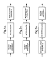
- Figure 1a shows the modulator of Figure 1 included in a concatenated modulation system which also includes a block code encoder and an interleaver.
- FIG 2 four input bits U1 to U4 are applied in parallel to input terminals 15 to 18 respectively and an input bit E1 is applied to an input terminal 19.
- the output from the convolutional encoder 20 consists of two bits C1 and C2 for each input bit E1.
- C1 and C2 represent the convolutional encoding of the input bit E1.
- the input bits U1 and U2 and the bit C1 are applied as input to an 8-PSK mapping circuit 21 while the input bits U3, U4 and the bit C2 are applied to an 8-PSK mapping circuit 22.
- Each of the mapping circuits 21 and 22 maps its respective three bits to a symbol of an 8-PSK modulated output.
- FIG 2a the modulator of Figure 2 is shown included in a concatenated modulation system which also includes a block code and an interleaver.
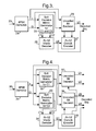
- a decoder has an input terminal 23 to receive the 8-PSK modulated signal output from the encoder of Figure 1.
- a demodulator 24 demodulates the 8-PSK modulated signal to produce I and Q quadrature components.
- the I and Q components are supplied to a module 25 which applies a soft-decision metric to the I and Q components to regenerate the bits C1 and C2 of each symbol.
- the bits C1 and C2 are applied to a Viterbi decoder 26 which decodes the bits C1 and C2 to reproduce the encoded bit E1 of each symbol.
- the convolutionally encoded bits from the encoder 27 are applied to a module 28.
- the module 28 receives the quadrature components I and Q from the demodulator 24 and produces a bit decision for each symbol.
- the bit decision specifies the uncoded bit U1 and is determined by the I and Q components from the demodulator 24 and the convolutionally encoded bits from the encoder 27.
- the output E1 from the decoder 26 and the output U1 from the module 28 represent the decoded output from the decoder.
- FIG 3a the demodulator of Figure 3 is shown incorporated into a system which also includes a de-interleaver and a block code decoder.
- a decoder has an input terminal 30 to receive the 8-PSK modulated signal output from the encoder of Figure 2.
- a demodulator 31 demodulates the 8-PSK modulated signal to produce I and Q quadrature components.
- the I and Q components are supplied to modules 32 and 33 which apply soft decision metrics to regenerate the bits C1 and C2 respectively.
- the two convolutionally encoded bits from the encoder 35 are applied to two modules 36 and 37 respectively.
- the module 36 receives the quadrature components I and Q from the demodulator 31 and produces bit decisions specifying the uncoded bits U1 and U2. The bit decisions depend on the I and Q components from the demodulator 31 and the convolutionally encoded bit from the encoder 35.
- the module 37 receives the quadrature components I and Q from the demodulator 31 and produces bit decisions specifying the uncoded bits U3 and U4. The bit decisions produced by the module 37 depend on the I and Q components from the demodulator 31 and the convolutionally encoded bit from the encoder 35.
- the output E1 from the decoder 34 and the outputs U1 to U4 from the modules 36 and 37 represent the decoded output from the decoder.
- FIG 4a the demodulator of Figure 4 is shown incorporated into a system which also includes a de-interleaver and a block code decoder.
- each bit regenerated by application of a soft decision metric to have an associated measure of the probability of the bit having been generated correctly. This measure is known as the reliability value.
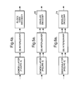
- Figure 5 shows a decoder for decoding the modulated signal generated by the modulator of Figure 1.
- the decoder of Figure 5 is an improvement, according to the present invention, over the decoder of Figure 3, in that it also outputs reliability information that can be used by an outer erasure decoder.
- the decoder of Figure 5 receives the 8-PSK modulated signal from the modulator of Figure 1 through an input terminal 38.
- a demodulator 39 demodulates the 8-PSK modulated signal to produce I and Q quadrature components.
- the I and Q components are supplied to a module 40 which applies a soft decision metric to the I and Q components to regenerate the bits C1 and C2 of each symbol.
- the bits C1 and C2 are applied to a Viterbi decoder 41 which decodes the bits C1 and C2 to reproduce the encoded bit E1 of each symbol.
- the convolutionally encoded bits from the encoder 42 are applied to a module 43.
- the module 43 receives the quadrature components I and Q from the demodulator 39 and produces a hard decision estimation of the uncoded bit in each symbol.
- the hard bit decision specifies the uncoded bit U1 and is determined by the I and Q components from the demodulator 39 and the convolutionally encoded bits from the encoder 42.
- the output E1 from the Viterbi decoder 41 is the same as the output which is produced by the Viterbi decoder 26 of Figure 3 and the output U1 from the module 43 is the same as the output which is produced by the module 28 of Figure 3. In the Figure 5 decoder, however these outputs are supplied to a multiplexer 44 which multiplexes the bits and supplies them to an erasure locator 45.
- a module 47 receives the I and Q quadrature components from the demodulator 39 in parallel with the modules 40 and 43.
- the module 47 applies a soft decision metric to generate a soft decision estimation for the uncoded bit by reference to the I and Q components and by reference to the output from the convolutional encoder 42.
- the soft decision estimation from the module 47 is supplied as a second input to the erasure locator 45.
- the erasure locator 45 operates in conventional manner to signal erasure locations in the symbols received at the input terminal 38 based on the inputs from the multiplexer 44 and from the module 47. For every soft value of U1 that is received by the erasure locator 45, there are two hard decision values U1 and E1.
- the erasure locator accumulates 8 hard decision values, 4 soft decision values and generates one symbol from the GF(2 8 ). If the lowest reliability value is acknowledged as an erasure, the whole symbol will be treated as an erasure and the erasure locator generates a value of "1". If the received symbol is acknowledged as reliable, the erasure locator generates a "0".
- Figure 5a shows a concatenated demodulation scheme for the modulated signal produced by the modulator shown in Figure 1a. According to the present invention, this gives a performance improvement over the demodulator of Figure 3a by passing erasure locations to the outer block code decoder 46.
- the erasure decoder 46 is shown in further detail in Figure 7.
- the hard data from the multiplexer 44 is applied at an input terminal 48 to a hard Reed Solomon decoder 49 and an erasure Reed Solomon decoder 50.
- the erasure locations from the erasure locator 45 are applied to an input terminal 51 to the erasure decoder 50.
- Each of the decoders 49 and 50 provides two output signals.
- the decoder 49 provides an output signal IN1 on a terminal 52 which represents the decoded information symbol and a control signal C1 on a terminal 53.
- the control signal C1 has a value of 0 if the decoder 49 is capable of correctly decoding the received code and has a value of 1 if the number of errors in the received code exceeds the error control capability of the code.
- the decoder 50 provides an output signal IN2 on a terminal 54 which represents the decoded information symbol and a control signal C2 on a terminal 55.
- the control signal C2 has a value of 0 if the decoder 50 is capable of correctly decoding the received code and has a value of 1 if the number of errors in the received code exceeds the error control capability of the code.
- the signals IN1, IN2, C1 and C2 on the terminals 52 to 55 are supplied to a multiplexer 56.
- the multiplexer 56 produces an INFO signal on an output terminal 57 and a control signal on an output terminal 58 according to the following look-up Table I; Control Signal C1 Control Signal C2 INFO Signal Out CONTROL Signal Out 0 0 IN1 0 0 1 IN1 0 1 0 IN2 0 1 1 IN1 1
- the control terminal 58 receives a control signal 0;
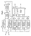
- Figure 6 shows a decoder for decoding the modulated signal generated by the modulator of Figure 2.
- the decoder of Figure 6 is an improvement, according to the present invention, over the decoder of Figure 4, in that it outputs additional reliability information that can be used by an outer erasure decoder.
- the decoder of Figure 6 receives the 8-PSK modulated signal from the modulator of Figure 2.
- the decoder includes a demodulator (not shown) which demodulates the 8-PSK modulated signal to produce I and Q quadrature components on terminals 59 and 60.
- the I and Q components are supplied to modules 62 and 63 which apply soft decision metrics to regenerate the bits C1 and C2 respectively.
- the two convolutionally encoded bits from the encoder 65 are applied to two terminals 66 and 67 respectively.
- the terminal 66 is connected to modules 68 and 69 and the terminal 67 is connected to modules 70 and 71.
- the modules 68, 69, 70 and 71 are connected to receive the I and Q quadrature components from the input terminals 59 and 60.
- the modules 68 and 69 produce hard and soft decision estimates of the bits U1 and U2 and the modules 70 and 71 produce hard and soft decision estimates of the bits U3 and U4.
- the hard decision estimates U1 to U4 and the estimate of E1 are applied to a multiplexer 72.
- the soft decision estimates U1 to U4 are applied to an erasure locator 73.
- Figure 6a shows a concatenated demodulation scheme for the modulated signal produced by the modulator in Figure 2a. According the present invention, this gives a performance improvement over the modulator of Figure 4a, by passing erasure locations to the outer block code.
- the erasure decoder 74 is as shown in Figure 7, the construction and operation of which has already been described.
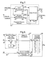
- Figure 8 shows the construction of the module 47 in the decoder of Figure 5.
- the I and Q quadrature components from the demodulator 39 are supplied to the module 47 through terminals 75 and 76.
- the convolutionally encoded bits C1 and C2 from the encoder 42 are supplied through terminals 77 and 78.
- the terminals 77 and 78 are connected to a reference signal generator 79 which generates reference signals I R and Q R according to the following Table II: C1 C2 I R ; Q R 0 0 (cos ⁇ /8;sin ⁇ /8) 0 1 (cos3 ⁇ /8;sin3 ⁇ /8) 1 0 (cos ⁇ /8;-sin ⁇ /8) 1 1 (cos3 ⁇ /8;-sin3 ⁇ /8)
- the signals I R and Q R are applied to a Euclidean distance calculating module 80a and to a change of sign module 81.
- the module 81 changes the signs of the signals I R and Q R to produce signals -I R and -Q R which are applied to a Euclidean distance calculating module 80b.
- the received signal components I and Q on the input terminals 75 and 76 are applied to the modules 80a and 80b.
- Each module calculates the Euclidean distance between the received signal components I and Q and the reference signals from the generator 79 to produce output signals d 1 2 and d 2 2 .
- the signals d 1 2 and d 2 2 are applied to a compare and select block 82 which compares those signals and selects the minimum value d 1 2 -d 2 2 between the calculated Euclidean distances.
- the selected value is normalised by means of a module 83 with reference to an erasure threshold Ao. If d 1 2 -d 2 2 ⁇ A 0 an erasure is declared.
- a 0 is defined in relation to the channel conditions.
- the reliability value of the uncoded bit is a complex function which depends on the probability density function of the noise, signal-to-noise ratio in the channel and the set partitioning of the pragmatic trellis coded modulation.
- the normalisation provides good matching for the Additive White Gaussian Channel Noise.
- input symbols comprising bits X1 and X2 are entered on lines 84 and 85 in a first stage.
- An interference filter precoder 86 is used to precode the bits on line 84.
- the output bits from the trellis encoder, labelled Z0, Z1, and Z2 are applied to an 8-level symbol mapper 88 which maps the values of the bits Z0, Z1 and Z2 to values R for an 8-VSB modulation.
Landscapes
- Physics & Mathematics (AREA)
- Probability & Statistics with Applications (AREA)
- Engineering & Computer Science (AREA)
- Theoretical Computer Science (AREA)
- Mathematical Physics (AREA)
- Algebra (AREA)
- General Physics & Mathematics (AREA)
- Pure & Applied Mathematics (AREA)
- Digital Transmission Methods That Use Modulated Carrier Waves (AREA)
- Error Detection And Correction (AREA)
Applications Claiming Priority (2)
| Application Number | Priority Date | Filing Date | Title |
|---|---|---|---|
| GBGB9902810.2A GB9902810D0 (en) | 1999-02-09 | 1999-02-09 | Indicating the reliability of uncoded bits in an input digital signal |
| GB9902810 | 1999-02-09 |
Publications (1)
| Publication Number | Publication Date |
|---|---|
| EP1028534A1 true EP1028534A1 (de) | 2000-08-16 |
Family
ID=10847354
Family Applications (1)
| Application Number | Title | Priority Date | Filing Date |
|---|---|---|---|
| EP00200353A Withdrawn EP1028534A1 (de) | 1999-02-09 | 2000-02-03 | Anzeigen der Zuverlässigkeit unkodierter Bits in einem digitalen Eingangssignal |
Country Status (2)
| Country | Link |
|---|---|
| EP (1) | EP1028534A1 (de) |
| GB (1) | GB9902810D0 (de) |
Cited By (1)
| Publication number | Priority date | Publication date | Assignee | Title |
|---|---|---|---|---|
| WO2008045292A3 (en) * | 2006-10-04 | 2008-07-03 | Marvell World Trade Ltd | Error correction decoding methods and apparatus |
Citations (3)
| Publication number | Priority date | Publication date | Assignee | Title |
|---|---|---|---|---|
| US4827489A (en) * | 1986-05-02 | 1989-05-02 | Hitachi, Ltd. | Decoding device for digital signals |
| EP0652643A2 (de) * | 1993-11-04 | 1995-05-10 | Kabushiki Kaisha Toshiba | Vorrichtung und Verfahren für Trellis-Dekoder |
| FR2754960A1 (fr) * | 1996-10-18 | 1998-04-24 | Mitsubishi Electric Corp | Decodeur de correction d'erreurs et procede de decodage utilisant ce decodeur |
-
1999
- 1999-02-09 GB GBGB9902810.2A patent/GB9902810D0/en not_active Ceased
-
2000
- 2000-02-03 EP EP00200353A patent/EP1028534A1/de not_active Withdrawn
Patent Citations (3)
| Publication number | Priority date | Publication date | Assignee | Title |
|---|---|---|---|---|
| US4827489A (en) * | 1986-05-02 | 1989-05-02 | Hitachi, Ltd. | Decoding device for digital signals |
| EP0652643A2 (de) * | 1993-11-04 | 1995-05-10 | Kabushiki Kaisha Toshiba | Vorrichtung und Verfahren für Trellis-Dekoder |
| FR2754960A1 (fr) * | 1996-10-18 | 1998-04-24 | Mitsubishi Electric Corp | Decodeur de correction d'erreurs et procede de decodage utilisant ce decodeur |
Non-Patent Citations (1)
| Title |
|---|
| WANG HUA ET AL: "A Concatenating Coding Scheme Employing Pragmatic Multidimensional Trellis Code and RS Code for Satellite Communications", INTERNATIONAL CONFERENCE ON COMMUNICATION TECHNOLOGY ICCT'98, 22 October 1998 (1998-10-22) - 24 October 1998 (1998-10-24), Beijing, China, pages S38.10.1 - S38.10.4, XP002136537 * |
Cited By (2)
| Publication number | Priority date | Publication date | Assignee | Title |
|---|---|---|---|---|
| WO2008045292A3 (en) * | 2006-10-04 | 2008-07-03 | Marvell World Trade Ltd | Error correction decoding methods and apparatus |
| US8032812B1 (en) | 2006-10-04 | 2011-10-04 | Marvell World Trade Ltd. | Error correction decoding methods and apparatus |
Also Published As
| Publication number | Publication date |
|---|---|
| GB9902810D0 (en) | 1999-03-31 |
Similar Documents
| Publication | Publication Date | Title |
|---|---|---|
| KR100247373B1 (ko) | 신호 송신 장치, 신호 수신 장치, 및 신호 송수신방법 | |
| US7865812B2 (en) | Apparatus and method for determining a detected punctured position in punctured convolutional codes | |
| US6738949B2 (en) | Error correction circuit and error correction method | |
| US7609787B2 (en) | Reception of a signal modulated according to a multilevel coding technique | |
| KR100351829B1 (ko) | 디지털 통신 시스템 | |
| US5134635A (en) | Convolutional decoder using soft-decision decoding with channel state information | |
| KR100971454B1 (ko) | 역방향 호환가능 dvb-s 표준 전송 시스템 | |
| US6160854A (en) | Concatenated trellis coded modulation and linear block codes | |
| US7460606B2 (en) | VSB transmission system | |
| EP0680184A2 (de) | Verfahren und Einrichtung zur Dekodierung von trelliskodierten QAM-Signalen | |
| USRE38010E1 (en) | Trellis encoder and decoder based upon punctured rate ½ convolutional codes | |
| KR100768770B1 (ko) | 인핸스드 슬라이스 예측 피드백 | |
| US8875000B2 (en) | Methods and systems systems for encoding and decoding in trellis coded modulation systems | |
| US6977972B1 (en) | Method of hybrid soft/hard decision demodulation of signals with multilevel modulation | |
| GB2414638A (en) | Decoding a concatenated convolutional-encoded and block encoded signal | |
| CN101674155B (zh) | 数字通信装置及解码方法 | |
| US8286051B2 (en) | Method and apparatus for burst error detection and digital communication device | |
| US6611940B1 (en) | Decoding symbols representing digital words | |
| JP3676460B2 (ja) | 入力変調信号の復号化装置 | |
| EP1028533A1 (de) | Dekodierung eines digitalen Eingangssignals | |
| EP1028534A1 (de) | Anzeigen der Zuverlässigkeit unkodierter Bits in einem digitalen Eingangssignal | |
| US7388522B2 (en) | Sequentially decoded low density parity coding (LDPC) forward error correction (FEC) in orthogonal frequency division modulation (OFDM) systems | |
| KR20030065866A (ko) | 채널상태정보를 적용된 데이터 에러 정정장치 | |
| CN118677535B (zh) | 相干光通信数字多载波系统中联合调制编码方法及系统 | |
| US7292643B1 (en) | MIMO TCM with constellation rotation and coordinate swapping |
Legal Events
| Date | Code | Title | Description |
|---|---|---|---|
| PUAI | Public reference made under article 153(3) epc to a published international application that has entered the european phase |
Free format text: ORIGINAL CODE: 0009012 |
|
| AK | Designated contracting states |
Kind code of ref document: A1 Designated state(s): DE FR GB |
|
| AX | Request for extension of the european patent |
Free format text: AL;LT;LV;MK;RO;SI |
|
| 17P | Request for examination filed |
Effective date: 20010216 |
|
| AKX | Designation fees paid |
Free format text: DE FR GB |
|
| GRAG | Despatch of communication of intention to grant |
Free format text: ORIGINAL CODE: EPIDOS AGRA |
|
| 17Q | First examination report despatched |
Effective date: 20020319 |
|
| GRAG | Despatch of communication of intention to grant |
Free format text: ORIGINAL CODE: EPIDOS AGRA |
|
| GRAH | Despatch of communication of intention to grant a patent |
Free format text: ORIGINAL CODE: EPIDOS IGRA |
|
| STAA | Information on the status of an ep patent application or granted ep patent |
Free format text: STATUS: THE APPLICATION IS DEEMED TO BE WITHDRAWN |
|
| 18D | Application deemed to be withdrawn |
Effective date: 20020917 |