EP1027990A1 - Ink jet printing head and production method thereof - Google Patents
Ink jet printing head and production method thereof Download PDFInfo
- Publication number
- EP1027990A1 EP1027990A1 EP00102071A EP00102071A EP1027990A1 EP 1027990 A1 EP1027990 A1 EP 1027990A1 EP 00102071 A EP00102071 A EP 00102071A EP 00102071 A EP00102071 A EP 00102071A EP 1027990 A1 EP1027990 A1 EP 1027990A1
- Authority
- EP
- European Patent Office
- Prior art keywords
- ink
- pressure
- plates
- thermosetting adhesive
- plate
- Prior art date
- Legal status (The legal status is an assumption and is not a legal conclusion. Google has not performed a legal analysis and makes no representation as to the accuracy of the status listed.)
- Withdrawn
Links
- 238000007641 inkjet printing Methods 0.000 title claims description 40
- 238000004519 manufacturing process Methods 0.000 title claims description 34
- 239000000853 adhesive Substances 0.000 claims abstract description 79
- 230000001070 adhesive effect Effects 0.000 claims abstract description 79
- 229920001187 thermosetting polymer Polymers 0.000 claims abstract description 70
- 230000005855 radiation Effects 0.000 claims description 12
- 238000003825 pressing Methods 0.000 claims description 11
- 238000010438 heat treatment Methods 0.000 claims description 9
- VYPSYNLAJGMNEJ-UHFFFAOYSA-N Silicium dioxide Chemical group O=[Si]=O VYPSYNLAJGMNEJ-UHFFFAOYSA-N 0.000 claims description 7
- 238000007599 discharging Methods 0.000 claims description 7
- 230000000712 assembly Effects 0.000 claims description 6
- 238000000429 assembly Methods 0.000 claims description 6
- 238000011176 pooling Methods 0.000 claims description 5
- 238000000034 method Methods 0.000 claims description 4
- 230000000116 mitigating effect Effects 0.000 claims description 4
- 238000000059 patterning Methods 0.000 claims description 2
- 230000004520 agglutination Effects 0.000 description 1
- 230000003247 decreasing effect Effects 0.000 description 1
- 239000007788 liquid Substances 0.000 description 1
- 239000000463 material Substances 0.000 description 1
- 238000005549 size reduction Methods 0.000 description 1
- 229920001169 thermoplastic Polymers 0.000 description 1
- 239000004416 thermosoftening plastic Substances 0.000 description 1
Images




Classifications
-
- B—PERFORMING OPERATIONS; TRANSPORTING
- B41—PRINTING; LINING MACHINES; TYPEWRITERS; STAMPS
- B41J—TYPEWRITERS; SELECTIVE PRINTING MECHANISMS, i.e. MECHANISMS PRINTING OTHERWISE THAN FROM A FORME; CORRECTION OF TYPOGRAPHICAL ERRORS
- B41J2/00—Typewriters or selective printing mechanisms characterised by the printing or marking process for which they are designed
- B41J2/005—Typewriters or selective printing mechanisms characterised by the printing or marking process for which they are designed characterised by bringing liquid or particles selectively into contact with a printing material
- B41J2/01—Ink jet
- B41J2/135—Nozzles
- B41J2/16—Production of nozzles
- B41J2/1621—Manufacturing processes
- B41J2/1623—Manufacturing processes bonding and adhesion
-
- B—PERFORMING OPERATIONS; TRANSPORTING
- B41—PRINTING; LINING MACHINES; TYPEWRITERS; STAMPS
- B41J—TYPEWRITERS; SELECTIVE PRINTING MECHANISMS, i.e. MECHANISMS PRINTING OTHERWISE THAN FROM A FORME; CORRECTION OF TYPOGRAPHICAL ERRORS
- B41J2/00—Typewriters or selective printing mechanisms characterised by the printing or marking process for which they are designed
- B41J2/005—Typewriters or selective printing mechanisms characterised by the printing or marking process for which they are designed characterised by bringing liquid or particles selectively into contact with a printing material
- B41J2/01—Ink jet
- B41J2/135—Nozzles
- B41J2/14—Structure thereof only for on-demand ink jet heads
- B41J2/14201—Structure of print heads with piezoelectric elements
- B41J2/14274—Structure of print heads with piezoelectric elements of stacked structure type, deformed by compression/extension and disposed on a diaphragm
-
- B—PERFORMING OPERATIONS; TRANSPORTING
- B41—PRINTING; LINING MACHINES; TYPEWRITERS; STAMPS
- B41J—TYPEWRITERS; SELECTIVE PRINTING MECHANISMS, i.e. MECHANISMS PRINTING OTHERWISE THAN FROM A FORME; CORRECTION OF TYPOGRAPHICAL ERRORS
- B41J2/00—Typewriters or selective printing mechanisms characterised by the printing or marking process for which they are designed
- B41J2/005—Typewriters or selective printing mechanisms characterised by the printing or marking process for which they are designed characterised by bringing liquid or particles selectively into contact with a printing material
- B41J2/01—Ink jet
- B41J2/135—Nozzles
- B41J2/16—Production of nozzles
- B41J2/1607—Production of print heads with piezoelectric elements
- B41J2/161—Production of print heads with piezoelectric elements of film type, deformed by bending and disposed on a diaphragm
-
- B—PERFORMING OPERATIONS; TRANSPORTING
- B41—PRINTING; LINING MACHINES; TYPEWRITERS; STAMPS
- B41J—TYPEWRITERS; SELECTIVE PRINTING MECHANISMS, i.e. MECHANISMS PRINTING OTHERWISE THAN FROM A FORME; CORRECTION OF TYPOGRAPHICAL ERRORS
- B41J2/00—Typewriters or selective printing mechanisms characterised by the printing or marking process for which they are designed
- B41J2/005—Typewriters or selective printing mechanisms characterised by the printing or marking process for which they are designed characterised by bringing liquid or particles selectively into contact with a printing material
- B41J2/01—Ink jet
- B41J2/135—Nozzles
- B41J2/14—Structure thereof only for on-demand ink jet heads
- B41J2002/14387—Front shooter
-
- B—PERFORMING OPERATIONS; TRANSPORTING
- B41—PRINTING; LINING MACHINES; TYPEWRITERS; STAMPS
- B41J—TYPEWRITERS; SELECTIVE PRINTING MECHANISMS, i.e. MECHANISMS PRINTING OTHERWISE THAN FROM A FORME; CORRECTION OF TYPOGRAPHICAL ERRORS
- B41J2/00—Typewriters or selective printing mechanisms characterised by the printing or marking process for which they are designed
- B41J2/005—Typewriters or selective printing mechanisms characterised by the printing or marking process for which they are designed characterised by bringing liquid or particles selectively into contact with a printing material
- B41J2/01—Ink jet
- B41J2/135—Nozzles
- B41J2/14—Structure thereof only for on-demand ink jet heads
- B41J2002/14419—Manifold
Definitions
- the present invention relates to an ink jet printing head capable of preventing clogging of fine holes and the production method thereof.
- the ink jet printing head selectively discharges ink from a pressure chamber for recording on a recording medium according to a pressure change of a piezoelectric device for example.
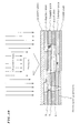
- such an ink jet printing head includes: a nozzle plate 2, a damper plate 3, pool plate 4, a supply plate 5, a chamber plate 6 and a vibration plate 7 which are connected together by a thermal hardening adhesive 9, and which constitute a flow path board 1.
- symbol 10 indicates an ink advance path
- symbol 11 indicates a pool
- symbol 12 a supply hole
- symbol 13 a pressure chamber
- symbol 14 a nozzle communication hole
- symbol 15 a nozzle hole
- the ink pooled in the pool 11 flows through the supply hole 12 of the supply plate into the pressure chamber 13.
- the ink in the pressure chamber 13 further flows from the nozzle communication hole 14 into the nozzle hole 15. In this state, the pressure chamber 13 is subjected to a pressure wave and the ink is discharged from the nozzle hole 15.
- Each of the plates of the flow path board 1 is attached to one another with a thermal hardening type adhesive 9 painted and then superimposed and subjected to pressure.
- thermosetting adhesive thermosetting adhesive
- thermoplastic adhesive anaerobic adhesive
- two-liquid adhesive film-shaped adhesive, and the like.
- thermosetting adhesive 9 is used in general.
- thermosetting adhesive has a characteristic that the viscosity is lowered during heating for setting.
- the thermosetting adhesive 9 applied to the respective plates flows out and may close the small nozzle hole 15 as shown in B portion of Fig. 13. This significantly affects the yield.
- thermosetting adhesive 9 t he attachment strength of the plates may be insufficient. Furthermore, as shown at C in Fig. 13, air tightness between the plates is lost, which results in ink leak. Insufficient strength and ink leak result in lowered quality.
- An ink jet printing head claimed in Claim 1 comprises a flow path board including a plurality of plates having an ink flow hole, wherein the plurality of plates are superimposed in such a manner that respective ink flow holes are matched and a stepped portion is formed between the respective ink flow holes, and pressure is applied so that a thermosetting adhesive applied between the plurality of plates with a predetermined thickness protrudes so as to fill the stepped portions, and ultraviolet ray is applied to harden the thermosetting adhesive so as to attach the plates to one another.
- the plurality of plates may comprise: a nozzle plate having a plurality of nozzles for discharging ink; a damper plate having a nozzle communication hole for mitigating a sadden pressure fluctuation during ink discharge; a pool plate having a nozzle communication hole and a pool for pooling ink in the head; a supply plate having an ink advance path, a supply path, and a nozzle communication hole for supplying ink from the pool plate to respective pressure chambers; a chamber plate having an ink advance path and the pressure chamber for generating a pressure wave for discharging the ink; and a vibration plate having an ink advance path and transmitting a pressure from a pressure generation source as a pressure wave to the pressure chamber; wherein the ink flow hole may include the nozzle hole, ink advance path, supply hole, and nozzle communication hole.
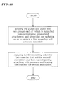
- the ink jet printing head production method claimed in Claim 3 is for producing an ink jet printing head comprising a flow path board including a plurality of plates having an ink flow hole, the method comprising: a first step for applying a thermosetting adhesive of a predetermined thickness to one side of the plurality of plates; a second step for applying a low-energy ultraviolet ray to the thermosetting adhesive; a third step for superimposing the plurality of plates while matching the ink flow holes and positioning the plates so that a stepped portion is formed between the respective plates and applying pressure to attach the plates to one another; and a fourth step for applying ultraviolet ray of a predetermined energy to the plurality of plates, so as to harden the thermosetting adhesive.
- the first step may include: a step for applying the thermosetting adhesive to a nozzle plate having a plurality of nozzles for discharging ink; a step for applying the thermosetting adhesive to a damper plate having a nozzle communication hole for mitigating a sadden pressure fluctuation during the ink discharge; a step for applying the thermosetting adhesive to a pool plate having a nozzle communication hole and a pool for pooling the ink in the head; a step for applying the thermosetting adhesive to a supply plate having an ink advance path, a supply hole, and a nozzle communication hole for supplying the ink from the pool plate to respective pressure chambers; and a step for applying the thermosetting adhesive to a chamber plate having an ink advance path and the pressure chamber for generating a pressure wave for discharge; and the third step may include a step for pressuring the plurality of plates so as to fill the stepped portions between the ink flow holes; and the fourth step may include a step of heating after the thermosetting adhesive is applied and the vibration plate is positioned
- the first step may include a step for applying the thermosetting adhesive having viscosity of 4000 cps so as to form a film thickness of about 1.8 micrometers
- the second step may include a step for setting the ultraviolet ray to about 4J/cm 2
- the third step may include a step for setting the pressure load to about 6 kgf/cm 2 .
- the method may further comprise: a fifth step for dividing the plurality of plates into two groups, each of which is subjected to superimposing, attaching with pressure, and ultraviolet ray radiation so as to prepare a first assembly and a second assembly; and a sixth step for applying the thermosetting adhesive between the first and the second assemblies and then superimposing, attaching with pressure, applying pressure and heating the first and the second assemblies.
- the fifth step may include a step for pressuring the first assembly with 4 ⁇ 2 kgf/cm 2 and a step for pressuring the second assembly with 8 ⁇ 2 kgf/cm 2
- the sixth step may include a step for pressurizing the first and the second assemblies with 8 kgf/cm 2 .
- the first step may include a step for patterning the thermosetting adhesive according to configurations of the respective plates when applying the thermosetting adhesive to the plates.
- the second step may include a step for hardening of the thermosetting adhesive by ultraviolet ray passed through a mask.
- pressure may be applied using a transparent member and simultaneously with this, ultraviolet ray is applied in third and fourth steps.
- the transparent member may be a quartz glass.
- the seventh step may include a step for gradually increasing the pressure so as to obtain a preferable protrusion of the thermosetting adhesive.
- thermosetting adhesive applied with a predetermined thickness between the plurality of plates protrudes so as to fill the stepped portions when subjected to pressure; and ultraviolet ray is applied for hardening of the thermosetting adhesive for attachment of the plurality of plates to one another.
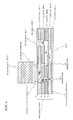
- Fig. 1 is a cross sectional view of an ink jet printing head according to a first embodiment of the present invention.
- Fig. 2 shows a production method of the ink jet printing head of Fig. 1.
- Fig. 3 shows a production method of the ink jet printing head of Fig. 1.
- Fig. 4 shows a production method of the ink jet printing head of Fig. 1.
- Fig. 5 shows a production method of the ink jet printing head of Fig. 1.
- Fig. 6 shows a production method of the ink jet printing head of Fig. 1.
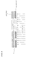
- Fig. 7 shows a production method of an ink jet printing head according to a second embodiment of the present invention.
- Fig. 8 shows a production method of an ink jet printing head according to a third embodiment of the present invention.
- Fig. 9 shows a production method of an ink jet printing head according to a fourth embodiment of the present invention.
- Fig. 10 shows a production method of an ink jet printing head according to a fifth embodiment of the present invention.
- Fig. 11 shows a flow Chart of the present invention.
- Fig. 12 shows another flow Chart of the present invention.
- Fig. 13 is a cross sectional view of a conventional ink jet printing head.
- Fig. 1 is a cross sectional view of an ink jet printing head (hereinafter, referred to simply as head) according to a first embodiment of the present invention, and Fig. 2 to Fig. 6 show a production method of the head shown in Fig. 1.
- the head shown in Fig. 1 comprises a flow path board 1.
- the flow path board 1 includes a nozzle plate 2, a damper plate 3, a pool plate 4, a supply plate 5, chamber plate 6, and a vibration plate 7.
- the nozzle plate 2 has a plurality of independent nozzle holes 15 for discharging ink.
- the damper plate 3 mitigates a sudden pressure fluctuation during ink discharge.
- the pool plate 4 has a pool 11 for pooling ink inside.
- the supply plate 5 has a supply hole 12 and a nozzle communication hole 14 for supplying ink from the pool plate 4 to the respective pressure chambers 13.
- the chamber plate 6 has a plurality of independent pressure chambers 13 for generating a pressure wave to discharge ink.
- the vibration plate 7 transmits deformation of the piezo actuator (PA) 8 as a pressure generation source, to the pressure chamber 13. From the pool plate 4 up to the vibration plate 7, there is provided an ink advance path 10 for introducing ink to the pool 11.
- PA piezo actuator
- thermosetting adhesive 9 The nozzle plate 2, the damper plate 3, the pool plate 4, the supply plate 5, and the chamber plate 6 are attached to one another by the thermosetting adhesive 9.
- the ink pooled in the pool 11 flows through the supply hole 12 of the supply plate 5 into the pressure chamber 13. Furthermore, the ink in the pressure chamber 13 flows from the nozzle communication hole 14 into the nozzle hole 15.
- the vibration plate 7 applies the deformation of the PA 8 as a pressure wave to the pressure chamber 13.
- the pressure wave is applied to the pressure chamber 13, the ink is discharged from the nozzle hole 15.
- thermosetting adhesive 9 having a viscosity of approximately 4000 cps is applied to one side of the damper plates 3 to the chamber plate 6, with a thickness of about 1.8 micrometers.
- thermosetting adhesive 9 may agglutinate, disturbing adhesive application of a uniform thickness.
- a low-energy ultraviolet ray is irradiated to prevent agglutination of the thermosetting adhesive 9.
- the radiation of the ultraviolet ray is preferably 4J/cm 2 .
- thermosetting adhesive 9 is pushed out in an amount preferable to cover a stepped portion between the respective plates from the nozzle plate 2 to the chamber plate 6.
- the step at one side is 25 micrometers.
- the load applied bring about the adhesive protrusion (width) not exceeding 25 micrometers.
- the preferable load may differ for each of the plates from the nozzle plate 2 to the chamber plate 6, it is preferable to select a load which can be applied to all of the plates in common.
- the load applied is set to about 6 kgf/cm 2 .
- thermosetting adhesive 9 is hardened by the radiation of the ultraviolet ray.
- thermosetting adhesive 9 is applied to the upper surface of the chamber plate 6.
- the vibration plate 7 is positioned and attached to the upper surface of the chamber plate 6.
- heat is applied from the side of the nozzle plate 2 so as to harden the thermosetting adhesive 9 applied to the respective plates from the damper plate 3 to the chamber plate 6.
- thermosetting adhesive 9 protruded to the stepped portions of the nozzle communication hole 14 and the nozzle hole 15 are hardened by the ultraviolet ray, so as to suppress the flow out of the thermosetting adhesive 9 during heating.
- Fig. 7 shows a production method of the ink jet printing head according to a second embodiment of the present invention. It should be noted that like components as in Fig. 1 to Fig. 6 are denoted by like reference symbols.
- a nozzle plate 2, a damper plate 3, and a pool plate 4 each having thermosetting adhesive 9 applied to one surface of them are subjected to superimposing, attaching with pressure, and ultraviolet ray radiation so as to prepare a nozzle assembly 16 as a first assembly.
- thermosetting adhesive 9 applied on one surface of them are subjected to superimposing, attaching with pressure, and ultraviolet ray radiation so as to prepare a chamber assembly 17 as a second assembly.
- thermosetting adhesive 9 is applied onto one surface of the nozzle assembly 16.
- the vibration plate 7, the nozzle assembly 16, and the chamber assembly 17 are subjected to superimposing, attaching with pressure, applying pressure and heating, so as to complete a flow path board 1.
- the nozzle assembly 16 and the chamber assembly 17 are prepared. Accordingly, in comparison to the first embodiment which is all-at-once production, it is possible to reduce the shaded portion in the ultraviolet ray radiation. This assures hardening of the thermosetting adhesive 9.
- a preferable load can be applied depending on the plate type and configuration from the nozzle plate 2 to the chamber plate 6. That is, for example, it is assumed that the most preferable load to be applied between the nozzle plate 2 and the pool plate 4 is 4 ⁇ 2 kgf/cm 2 and the most preferable load to be applied between the supply plate 5 and the chamber plate 6 is 8 ⁇ 2 kgf/cm 2 .
- 6 kgf/cm2 can be applied so that the plates from the nozzle plate 2 to the chamber plate 6 are subjected to superimposing, attaching with pressure, ultraviolet ray radiation, applying pressure and heating.
- a portion partially hardened serves as a wall and the most preferable load can be increased.
- Fig. 8 shows a production method of an ink jet printing head according to the third embodiment of the present invention.
- thermosetting adhesive 9 is patterned when applied to the respective plates from the damper plate 3 to the chamber plate 6.
- thermosetting adhesive 9 is patterned and applied to the damper plate 3, which is attached to the nozzle plate 2.
- the preferable load for protruding the thermosetting adhesive 9 is 4 ⁇ 2 kgf/cm 2 to 6 ⁇ 3 kgf/cm 2 .
- thermosetting adhesive 9 is patterned according to the configuration of the respective plates from the damper plate 3 to the chamber plate 6 and accordingly, a wider range is available in the protrusion control of the thermosetting adhesive 9.
- Fig. 9 shows a production method of the ink jet printing head according to the fourth embodiment of the present invention.
- thermosetting adhesive 9 is hardened by ultraviolet ray radiation in advance. Note that this hardening in advance can also be performed to the other plates from the damper plate 3 to the chamber plate 6.
- thermosetting adhesive 9 applied to the respective plates from the damper plate 3 to the chamber plate 6 are hardened using the mask 18.
- the hardened portions serve as walls when the respective plates from the damper plate 3 to the chamber plate 6 are superimposed and attached to one another.
- flow out of the thermosetting adhesive 9 can be controlled and suppressed.
- Fig. 10 shows a production method of the ink jet printing head according to the fifth embodiment of the present invention.
- a quartz glass 19 is used to pressurize the respective plates from the nozzle plate 2 to the chamber plate 6. Since the quartz glass 19 is transparent, it is possible to apply ultraviolet ray simultaneously.
- the quartz glass 19 is used to pressurize the respective plates from the nozzle plate 2 to the chamber plate 6 and simultaneously with this, ultraviolet ray is applied from the upper surface of the quartz glass 19. This significantly reduces the work time.
- the pressure may be gradually increased so as to obtain a preferable protrusion amount of the thermosetting adhesive 9 from the respective plates from the damper plate 3 to the chamber plate 6.
- thermosetting adhesive 9 even if the pressure to obtain the preferable protrusion of thermosetting adhesive 9 varies between the respective plates from the damper plate 3 to the chamber plate 6, ultraviolet ray is applied at each pressuring step and accordingly, it is possible to obtain a preferable protrusion amount for the respective plates and the work time is reduced as well.
- thermosetting adhesive applied to the respective plates with a predetermined thickness protrudes so as to fill the stepped portions.
- ultraviolet ray is applied so that the plates are attached by hardening of the thermosetting adhesive. This significantly increases the yield and the quality.
Landscapes
- Engineering & Computer Science (AREA)
- Manufacturing & Machinery (AREA)
- Particle Formation And Scattering Control In Inkjet Printers (AREA)
Abstract
Description
- The present invention relates to an ink jet printing head capable of preventing clogging of fine holes and the production method thereof.
- The ink jet printing head selectively discharges ink from a pressure chamber for recording on a recording medium according to a pressure change of a piezoelectric device for example.
- As shown in Fig. 13, such an ink jet printing head includes: a
nozzle plate 2, adamper plate 3,pool plate 4, asupply plate 5, achamber plate 6 and avibration plate 7 which are connected together by athermal hardening adhesive 9, and which constitute aflow path board 1. - It should be noted that in the figure,
symbol 10 indicates an ink advance path;symbol 11 indicates a pool;symbol 12, a supply hole;symbol 13, a pressure chamber;symbol 14, a nozzle communication hole; andsymbol 15, a nozzle hole. - The ink pooled in the
pool 11 flows through thesupply hole 12 of the supply plate into thepressure chamber 13. The ink in thepressure chamber 13 further flows from thenozzle communication hole 14 into thenozzle hole 15. In this state, thepressure chamber 13 is subjected to a pressure wave and the ink is discharged from thenozzle hole 15. - Each of the plates of the
flow path board 1 is attached to one another with a thermal hardening type adhesive 9 painted and then superimposed and subjected to pressure. - For attachment of the aforementioned plates to one another, it is possible to use a cold setting adhesive, thermosetting adhesive, thermoplastic adhesive, anaerobic adhesive, two-liquid adhesive, film-shaped adhesive, and the like.
- From the viewpoints of reliability (ink resistance, air-tightness, strength and the like), workability, cost, and equipment size reduction, the aforementioned thermosetting adhesive 9 is used in general.
- However, the thermosetting adhesive has a characteristic that the viscosity is lowered during heating for setting. The
thermosetting adhesive 9 applied to the respective plates flows out and may close thesmall nozzle hole 15 as shown in B portion of Fig. 13. This significantly affects the yield. - Moreover, if a pressure and setting temperature are decreased so as to suppress flowing out of the thermosetting adhesive 9, t he attachment strength of the plates may be insufficient. Furthermore, as shown at C in Fig. 13, air tightness between the plates is lost, which results in ink leak. Insufficient strength and ink leak result in lowered quality.
- It is therefore an object of the present invention to provide an ink jet printing head capable of increasing the yield and improving the quality, and the production method thereof.
- An ink jet printing head claimed in
Claim 1 comprises a flow path board including a plurality of plates having an ink flow hole, wherein the plurality of plates are superimposed in such a manner that respective ink flow holes are matched and a stepped portion is formed between the respective ink flow holes, and pressure is applied so that a thermosetting adhesive applied between the plurality of plates with a predetermined thickness protrudes so as to fill the stepped portions, and ultraviolet ray is applied to harden the thermosetting adhesive so as to attach the plates to one another. - Moreover, the plurality of plates may comprise: a nozzle plate having a plurality of nozzles for discharging ink; a damper plate having a nozzle communication hole for mitigating a sadden pressure fluctuation during ink discharge; a pool plate having a nozzle communication hole and a pool for pooling ink in the head; a supply plate having an ink advance path, a supply path, and a nozzle communication hole for supplying ink from the pool plate to respective pressure chambers; a chamber plate having an ink advance path and the pressure chamber for generating a pressure wave for discharging the ink; and a vibration plate having an ink advance path and transmitting a pressure from a pressure generation source as a pressure wave to the pressure chamber; wherein the ink flow hole may include the nozzle hole, ink advance path, supply hole, and nozzle communication hole.
- The ink jet printing head production method claimed in
Claim 3 is for producing an ink jet printing head comprising a flow path board including a plurality of plates having an ink flow hole, the method comprising: a first step for applying a thermosetting adhesive of a predetermined thickness to one side of the plurality of plates; a second step for applying a low-energy ultraviolet ray to the thermosetting adhesive; a third step for superimposing the plurality of plates while matching the ink flow holes and positioning the plates so that a stepped portion is formed between the respective plates and applying pressure to attach the plates to one another; and a fourth step for applying ultraviolet ray of a predetermined energy to the plurality of plates, so as to harden the thermosetting adhesive. - Moreover, the first step may include: a step for applying the thermosetting adhesive to a nozzle plate having a plurality of nozzles for discharging ink; a step for applying the thermosetting adhesive to a damper plate having a nozzle communication hole for mitigating a sadden pressure fluctuation during the ink discharge; a step for applying the thermosetting adhesive to a pool plate having a nozzle communication hole and a pool for pooling the ink in the head; a step for applying the thermosetting adhesive to a supply plate having an ink advance path, a supply hole, and a nozzle communication hole for supplying the ink from the pool plate to respective pressure chambers; and a step for applying the thermosetting adhesive to a chamber plate having an ink advance path and the pressure chamber for generating a pressure wave for discharge; and the third step may include a step for pressuring the plurality of plates so as to fill the stepped portions between the ink flow holes; and the fourth step may include a step of heating after the thermosetting adhesive is applied and the vibration plate is positioned to be attached.
- Moreover, the first step may include a step for applying the thermosetting adhesive having viscosity of 4000 cps so as to form a film thickness of about 1.8 micrometers, and the second step may include a step for setting the ultraviolet ray to about 4J/cm2, and the third step may include a step for setting the pressure load to about 6 kgf/cm2.
- Moreover, the method (
steps 1 to 4) may further comprise: a fifth step for dividing the plurality of plates into two groups, each of which is subjected to superimposing, attaching with pressure, and ultraviolet ray radiation so as to prepare a first assembly and a second assembly; and a sixth step for applying the thermosetting adhesive between the first and the second assemblies and then superimposing, attaching with pressure, applying pressure and heating the first and the second assemblies. - Moreover, the fifth step may include a step for pressuring the first assembly with 4±2 kgf/cm2 and a step for pressuring the second assembly with 8±2 kgf/cm2, and the sixth step may include a step for pressurizing the first and the second assemblies with 8 kgf/cm2.
- Moreover, the first step may include a step for patterning the thermosetting adhesive according to configurations of the respective plates when applying the thermosetting adhesive to the plates.
- Moreover, the second step may include a step for hardening of the thermosetting adhesive by ultraviolet ray passed through a mask.
- Moreover, pressure may be applied using a transparent member and simultaneously with this, ultraviolet ray is applied in third and fourth steps.
- Moreover, the transparent member may be a quartz glass.
- Moreover, the seventh step may include a step for gradually increasing the pressure so as to obtain a preferable protrusion of the thermosetting adhesive.
- In the ink jet printing head and the production method thereof according to the present invention, a plurality of plates are superimposed in such a manner that the respective ink flow holes are matched with one another and stepped portions are formed between the ink flow holes; and a thermosetting adhesive applied with a predetermined thickness between the plurality of plates protrudes so as to fill the stepped portions when subjected to pressure; and ultraviolet ray is applied for hardening of the thermosetting adhesive for attachment of the plurality of plates to one another.
- Fig. 1 is a cross sectional view of an ink jet printing head according to a first embodiment of the present invention.
- Fig. 2 shows a production method of the ink jet printing head of Fig. 1.
- Fig. 3 shows a production method of the ink jet printing head of Fig. 1.
- Fig. 4 shows a production method of the ink jet printing head of Fig. 1.
- Fig. 5 shows a production method of the ink jet printing head of Fig. 1.
- Fig. 6 shows a production method of the ink jet printing head of Fig. 1.
- Fig. 7 shows a production method of an ink jet printing head according to a second embodiment of the present invention.
- Fig. 8 shows a production method of an ink jet printing head according to a third embodiment of the present invention.
- Fig. 9 shows a production method of an ink jet printing head according to a fourth embodiment of the present invention.
- Fig. 10 shows a production method of an ink jet printing head according to a fifth embodiment of the present invention.
- Fig. 11 shows a flow Chart of the present invention.
- Fig. 12 shows another flow Chart of the present invention.
- Fig. 13 is a cross sectional view of a conventional ink jet printing head.
- Hereinafter, explanation will be given on embodiments of the present invention with reference to the attached drawings. Note that components common to Fig. 11 are denoted by identical symbols.
- Fig. 1 is a cross sectional view of an ink jet printing head (hereinafter, referred to simply as head) according to a first embodiment of the present invention, and Fig. 2 to Fig. 6 show a production method of the head shown in Fig. 1.
- The head shown in Fig. 1 comprises a
flow path board 1. Theflow path board 1 includes anozzle plate 2, adamper plate 3, apool plate 4, asupply plate 5,chamber plate 6, and avibration plate 7. - The
nozzle plate 2 has a plurality ofindependent nozzle holes 15 for discharging ink. Thedamper plate 3 mitigates a sudden pressure fluctuation during ink discharge. - The
pool plate 4 has apool 11 for pooling ink inside. Thesupply plate 5 has asupply hole 12 and anozzle communication hole 14 for supplying ink from thepool plate 4 to therespective pressure chambers 13. - The
chamber plate 6 has a plurality ofindependent pressure chambers 13 for generating a pressure wave to discharge ink. - The
vibration plate 7 transmits deformation of the piezo actuator (PA) 8 as a pressure generation source, to thepressure chamber 13. From thepool plate 4 up to thevibration plate 7, there is provided anink advance path 10 for introducing ink to thepool 11. - The
nozzle plate 2, thedamper plate 3, thepool plate 4, thesupply plate 5, and thechamber plate 6 are attached to one another by thethermosetting adhesive 9. - The ink pooled in the
pool 11 flows through thesupply hole 12 of thesupply plate 5 into thepressure chamber 13. Furthermore, the ink in thepressure chamber 13 flows from thenozzle communication hole 14 into thenozzle hole 15. When thePA 8 is subjected to voltage in this state, thevibration plate 7 applies the deformation of thePA 8 as a pressure wave to thepressure chamber 13. When the pressure wave is applied to thepressure chamber 13, the ink is discharged from thenozzle hole 15. - Next, explanation will be given on the production method of the head having the aforementioned configuration with reference to Fig. 2 to Fig. 6.
- Firstly,
thermosetting adhesive 9 having a viscosity of approximately 4000 cps is applied to one side of thedamper plates 3 to thechamber plate 6, with a thickness of about 1.8 micrometers. - Here, depending on the material of the respective plates from the
damper plate 3 to thechamber plate 6, thethermosetting adhesive 9 may agglutinate, disturbing adhesive application of a uniform thickness. To cope with this, a low-energy ultraviolet ray is irradiated to prevent agglutination of thethermosetting adhesive 9. The radiation of the ultraviolet ray is preferably 4J/cm2. - Next, as shown in Fig. 3, the respective plates from the
nozzle plate 2 to thechamber plate 6 are positioned, superimposed, and attached to one another with pressure. Here, as shown at A in Fig. 3, thethermosetting adhesive 9 is pushed out in an amount preferable to cover a stepped portion between the respective plates from thenozzle plate 2 to thechamber plate 6. - For example, if it is assumed that the
nozzle hole 15 is 50 micrometers and thenozzle communication hole 14 of thedamper plate 3 is 100 micrometers, the step at one side is 25 micrometers. In this case, it is preferable that the load applied bring about the adhesive protrusion (width) not exceeding 25 micrometers. - The preferable load may differ for each of the plates from the
nozzle plate 2 to thechamber plate 6, it is preferable to select a load which can be applied to all of the plates in common. Here, the load applied is set to about 6 kgf/cm2. - Next, as shown in Fig. 4, ultraviolet ray of about 20J/cm2 is applied from the upper side of the
chamber plate 6. Here, the protruding portion of thethermosetting adhesive 9 is hardened by the radiation of the ultraviolet ray. - Next, as shown in Fig. 5, the
thermosetting adhesive 9 is applied to the upper surface of thechamber plate 6. After applying thethermosetting adhesive 9, as shown in Fig. 6, thevibration plate 7 is positioned and attached to the upper surface of thechamber plate 6. Moreover, heat is applied from the side of thenozzle plate 2 so as to harden thethermosetting adhesive 9 applied to the respective plates from thedamper plate 3 to thechamber plate 6. Thus, theflow path board 1 of the head is complete. - Thus, in this first embodiment, the
thermosetting adhesive 9 protruded to the stepped portions of thenozzle communication hole 14 and thenozzle hole 15 are hardened by the ultraviolet ray, so as to suppress the flow out of thethermosetting adhesive 9 during heating. This prevents ink clogging in thesupply hole 12, thenozzle communication hole 14, and thenozzle hole 15, and assures air tightness between the respective plates from thenozzle plate 2 to thevibration plate 7. Thus, it is possible to produce a product having a high reliability, with a high yield. - Fig. 7 shows a production method of the ink jet printing head according to a second embodiment of the present invention. It should be noted that like components as in Fig. 1 to Fig. 6 are denoted by like reference symbols.
- As shown in Fig. 7, firstly, a
nozzle plate 2, adamper plate 3, and apool plate 4 each having thermosetting adhesive 9 applied to one surface of them are subjected to superimposing, attaching with pressure, and ultraviolet ray radiation so as to prepare anozzle assembly 16 as a first assembly. - Moreover, a
supply plate 5 and achamber plate 6 having thermosetting adhesive 9 applied on one surface of them are subjected to superimposing, attaching with pressure, and ultraviolet ray radiation so as to prepare achamber assembly 17 as a second assembly. - Subsequently, the
thermosetting adhesive 9 is applied onto one surface of thenozzle assembly 16. Thevibration plate 7, thenozzle assembly 16, and thechamber assembly 17 are subjected to superimposing, attaching with pressure, applying pressure and heating, so as to complete aflow path board 1. - Thus, in the second embodiment, firstly, the
nozzle assembly 16 and thechamber assembly 17 are prepared. Accordingly, in comparison to the first embodiment which is all-at-once production, it is possible to reduce the shaded portion in the ultraviolet ray radiation. This assures hardening of thethermosetting adhesive 9. - Moreover, a preferable load can be applied depending on the plate type and configuration from the
nozzle plate 2 to thechamber plate 6. That is, for example, it is assumed that the most preferable load to be applied between thenozzle plate 2 and thepool plate 4 is 4 ± 2 kgf/cm2 and the most preferable load to be applied between thesupply plate 5 and thechamber plate 6 is 8 ± 2 kgf/cm2. - Here, 6 kgf/cm2 can be applied so that the plates from the
nozzle plate 2 to thechamber plate 6 are subjected to superimposing, attaching with pressure, ultraviolet ray radiation, applying pressure and heating. - In this case, 4 kgf/cm2 is set between the
nozzle plate 2 and thepool plate supply plate 5 and thechamber plate 6 for superimposing, attaching with pressure, ultraviolet ray radiation. - Here, a portion partially hardened serves as a wall and the most preferable load can be increased. For this, it is possible to apply 8 kgf/cm2 so as to perform superimposing, attaching with pressure, ultraviolet ray radiation, applying pressure and heating. This further improves reliability of the junction.
- Thus, when the pressurizing conditions differ between the plates from the
nozzle plate 2 to thechamber plate 6, it is possible to improve reliability by dividing the plates in two or more groups when performing the superimposing, applying pressure, ultraviolet ray radiation. - It should be noted that the respective plates from the
nozzle plate 2 to thechamber plate 6 may be superimposed in different order or in different combination depending on the configuration, production method, and production conditions and is not to be limited to the example of Fig. 7. - Fig. 8 shows a production method of an ink jet printing head according to the third embodiment of the present invention.
- In the third embodiment, the
thermosetting adhesive 9 is patterned when applied to the respective plates from thedamper plate 3 to thechamber plate 6. - That is, for example, the
thermosetting adhesive 9 is patterned and applied to thedamper plate 3, which is attached to thenozzle plate 2. Here, the preferable load for protruding thethermosetting adhesive 9 is 4±2 kgf/cm2 to 6±3 kgf/cm2. - This enables to set 8±2 kgf/cm2 for attaching the
nozzle plate 2 and thedamper plate 3 to thesupply plate 5 and thechamber plate 6, for example. - Thus, in the third embodiment, the
thermosetting adhesive 9 is patterned according to the configuration of the respective plates from thedamper plate 3 to thechamber plate 6 and accordingly, a wider range is available in the protrusion control of thethermosetting adhesive 9. - Thus, even in the all-at-once layering of the five plates, it is possible to improve reliability and reduce the work time.
- Fig. 9 shows a production method of the ink jet printing head according to the fourth embodiment of the present invention.
- In the fourth embodiment, a
mask 18 is used so that an end portion of thethermosetting adhesive 9 is hardened by ultraviolet ray radiation in advance. Note that this hardening in advance can also be performed to the other plates from thedamper plate 3 to thechamber plate 6. - Thus, in the fourth embodiment, the end portions of the
thermosetting adhesive 9 applied to the respective plates from thedamper plate 3 to thechamber plate 6 are hardened using themask 18. The hardened portions serve as walls when the respective plates from thedamper plate 3 to thechamber plate 6 are superimposed and attached to one another. Thus, flow out of thethermosetting adhesive 9 can be controlled and suppressed. - Fig. 10 shows a production method of the ink jet printing head according to the fifth embodiment of the present invention.
- In the fifth embodiment, a
quartz glass 19 is used to pressurize the respective plates from thenozzle plate 2 to thechamber plate 6. Since thequartz glass 19 is transparent, it is possible to apply ultraviolet ray simultaneously. - Thus, in the fifth embodiment, the
quartz glass 19 is used to pressurize the respective plates from thenozzle plate 2 to thechamber plate 6 and simultaneously with this, ultraviolet ray is applied from the upper surface of thequartz glass 19. This significantly reduces the work time. - It should be noted that during pressurizing with the
quartz glass 19, the pressure may be gradually increased so as to obtain a preferable protrusion amount of the thermosetting adhesive 9 from the respective plates from thedamper plate 3 to thechamber plate 6. - In this case, even if the pressure to obtain the preferable protrusion of
thermosetting adhesive 9 varies between the respective plates from thedamper plate 3 to thechamber plate 6, ultraviolet ray is applied at each pressuring step and accordingly, it is possible to obtain a preferable protrusion amount for the respective plates and the work time is reduced as well. - As has been described above, in the ink jet printing head and the production method thereof according to the present invention, a plurality of plates are superimposed so as to match ink flow holes and to form stepped portions between the plates. And pressure is applied so that the thermosetting adhesive applied to the respective plates with a predetermined thickness protrudes so as to fill the stepped portions. Furthermore, ultraviolet ray is applied so that the plates are attached by hardening of the thermosetting adhesive. This significantly increases the yield and the quality.
- The invention may be embodied in other specific forms without departing from the spirit or essential characteristic thereof. The present embodiments are therefore to be considered in all respects as illustrative and not restrictive, the scope of the invention being indicated by the appended claims rather than by the foregoing description and all changes which come within the meaning and range of equivalency of the claims are therefore intended to be embraced therein.
- The entire disclosure of Japanese Patent Application No. 11-024823 (Filed on February 2nd, 1999) including specification, claims, drawings and summary are incorporated herein by reference in its entirety.
Claims (12)
- An ink jet printing head comprising a flow path board (1) including a plurality of plates (2-7) having an ink flow hole (10,12,14,15),
wherein the plurality of plates (2-7) are superimposed in such a manner that respective ink flow holes (10,12,14,15) are matched and a stepped portion is formed between the respective ink flow holes (10,12,14,15), and pressure is applied so that a thermosetting adhesive (9) applied between the plurality of plates (2-7) with a predetermined thickness protrudes so as to fill the stepped portions, and ultraviolet ray is applied to harden the thermosetting adhesive (9) so as to attach the plates (2-7) to one another. - The ink jet printing head as claimed in Claim 1, said plurality of plates (2-7) comprise:a nozzle plate (2) having a plurality of nozzles (15) for discharging ink;a damper plate (3) having a nozzle communication hole (14) for mitigating a sadden pressure fluctuation during ink discharge;a pool plate (4) having a nozzle communication hole (14) and a pool (11) for pooling ink in the head;a supply plate (5) having an ink advance path (10), a supply path (12), and a nozzle communication hole (14) for supplying ink from the pool plate (4) to respective pressure chambers (13);a chamber plate (6) having an ink advance path (10) and the pressure chamber (13) for generating a pressure wave for discharging the ink; anda vibration plate (7) having an ink advance path (10) and transmitting a pressure from a pressure generation source (8) as a pressure wave to the pressure chamber (13);wherein the ink flow hole (10,12,14,15) includes the nozzle hole (15), ink advance path (10), supply hole (12), and nozzle communication hole (14).
- An ink jet printing head production method for producing an ink jet printing head comprising a flow path board (1) including a plurality of plates (2-7) having an ink flow hole (10,12,14,15), said method comprising:a first step for applying a thermosetting adhesive (9) of a predetermined thickness to one side of the plurality of plates (2-7);a second step for applying a low-energy ultraviolet ray to the thermosetting adhesive (9);a third step for superimposing the plurality of plates (2-7) while matching the ink flow holes (10,12, 14,15) and positioning the plates (2-7) so that a stepped portion is formed between the respective plates (2-7) and applying pressure to attach the plates (2-7) to one another; anda fourth step for applying ultraviolet ray of a predetermined energy to the plurality of plates (2-7), so as to harden the thermosetting adhesive (9).
- The ink jet printing head production method as claimed in Claim 3, wherein said first step includes:a step for applying the thermosetting adhesive (9) to a nozzle plate (2) having a plurality of nozzles (15) for discharging ink;a step for applying the thermosetting adhesive (9) to a damper plate (3) having a nozzle communication hole (14) for mitigating a sadden pressure fluctuation during the ink discharge;a step for applying the thermosetting adhesive (9) to a pool plate (4) having a nozzle communication hole (14) and a pool (11) for pooling the ink in the head;a step for applying the thermosetting adhesive (9) to a supply plate (5) having an ink advance path (10), a supply hole (12), and a nozzle communication hole (14) for supplying the ink from the pool plate (4) to respective pressure chambers (13); anda step for applying the thermosetting adhesive (9) to a chamber plate (6) having an ink advance path (10) and the pressure chamber (13) for generating a pressure wave for discharge,said third step includes a step for pressuring the plurality of plates (2-7) so as to fill the stepped portions between the ink flow holes (10,12,14,15); andsaid fourth step includes a step of heating after the thermosetting adhesive (9) is applied and the vibration plate (7) is positioned to be attached.
- The ink jet printing head production method as claimed in Claim 3, whereinsaid first step includes a step for applying the thermosetting adhesive (9) having viscosity of 4000 cps so as to form a film thickness of about 1.8 micrometers,said second step includes a step for setting the ultraviolet ray to about 4J/cm2, andsaid third step includes a step for setting the pressure load to about 6 kgf /cm2.
- An ink jet printing head production method for producing an ink jet printing head comprising a flow path board (1) including a plurality of plates (2-7) having an ink flow hole (10,12,14,15), said method comprising:a step for dividing the plurality of plates (2-7) into two groups, each of which is subjected to superimposing, attaching with pressure, and ultraviolet ray radiation so as to prepare a first assembly (16) and a second assembly (17); anda step for applying the thermosetting adhesive (9) between the first and the second assemblies (16,17) and then superimposing, attaching with pressure, applying pressure and heating the first and the second assemblies (16,17).
- The ink jet printing head production method as claimed in Claim 6, whereinapplying pressure to the first assembly (16) with 4±2 kgf /cm2 and applying pressure to the second assembly (17) with 8±2 kgf /cm2, andapplying pressure to first and the second assemblies with 8 kgf/cm2 (16,17).
- The ink jet printing head production method as claimed in Claim 3, wherein said first step includes a step for patterning the thermosetting adhesive (9) according to configurations of the respective plates (2-7) when applying the thermosetting adhesive (9) to the plates (2-7).
- The ink jet printing head production method as claimed in Claim 3, wherein said second step includes a step for hardening of the thermosetting adhesive (9) by ultraviolet ray passed through a mask (18).
- The ink jet printing head production method as claimed in Claim 3, wherein said third and fourth steps include seventh step for pressuring by using a transparent member (19) and simultaneously with this, applying ultraviolet ray from the transparent member side to the plurality of palettes (2-7).
- The ink jet printing head production method as claimed in Claim 10, wherein said transparent member is a quartz glass (19).
- The ink jet printing head production method as claimed in Claim 10, wherein pressure is gradually increasing so as to obtain a preferable protrusion of the thermosetting adhesive (9).
Applications Claiming Priority (2)
| Application Number | Priority Date | Filing Date | Title |
|---|---|---|---|
| JP2482399 | 1999-02-02 | ||
| JP2482399A JP3056195B1 (en) | 1999-02-02 | 1999-02-02 | INK JET PRINT HEAD AND ITS MANUFACTURING METHOD |
Publications (1)
| Publication Number | Publication Date |
|---|---|
| EP1027990A1 true EP1027990A1 (en) | 2000-08-16 |
Family
ID=12148912
Family Applications (1)
| Application Number | Title | Priority Date | Filing Date |
|---|---|---|---|
| EP00102071A Withdrawn EP1027990A1 (en) | 1999-02-02 | 2000-02-02 | Ink jet printing head and production method thereof |
Country Status (2)
| Country | Link |
|---|---|
| EP (1) | EP1027990A1 (en) |
| JP (1) | JP3056195B1 (en) |
Cited By (3)
| Publication number | Priority date | Publication date | Assignee | Title |
|---|---|---|---|---|
| EP1375148A1 (en) * | 2002-06-26 | 2004-01-02 | Brother Kogyo Kabushiki Kaisha | Ink-jet printhead |
| US7611231B2 (en) | 2004-10-28 | 2009-11-03 | Brother Kogyo Kabushiki Kaisha | Inkjet printhead |
| CN102407667A (en) * | 2010-09-20 | 2012-04-11 | 研能科技股份有限公司 | inkjet unit |
Families Citing this family (4)
| Publication number | Priority date | Publication date | Assignee | Title |
|---|---|---|---|---|
| JP4780875B2 (en) * | 2000-09-06 | 2011-09-28 | キヤノン株式会社 | Method for manufacturing ink jet recording head |
| KR101305718B1 (en) * | 2007-01-17 | 2013-09-09 | 엘지전자 주식회사 | Highly Integrated Inkjet Heads |
| JP5707806B2 (en) * | 2010-09-16 | 2015-04-30 | 株式会社リコー | Liquid ejection head and image forming apparatus |
| JP6988612B2 (en) * | 2018-03-19 | 2022-01-05 | 株式会社リコー | Liquid discharge head, liquid discharge unit and device for discharging liquid |
Citations (5)
| Publication number | Priority date | Publication date | Assignee | Title |
|---|---|---|---|---|
| WO1989007752A1 (en) * | 1988-02-22 | 1989-08-24 | Spectra, Inc. | Pressure chamber for ink jet systems |
| JPH08267764A (en) * | 1995-03-30 | 1996-10-15 | Fuji Electric Co Ltd | Method for manufacturing ink jet recording head |
| EP0830945A1 (en) * | 1996-04-04 | 1998-03-25 | Sony Corporation | Printer device and method of manufacturing same |
| EP0839655A2 (en) * | 1992-08-26 | 1998-05-06 | Seiko Epson Corporation | Multi-layer ink jet recording head |
| US5852456A (en) * | 1993-07-26 | 1998-12-22 | Ngk Insulators, Ltd. | Plate assembly suitable for ink-jet-type printing head |
-
1999
- 1999-02-02 JP JP2482399A patent/JP3056195B1/en not_active Expired - Fee Related
-
2000
- 2000-02-02 EP EP00102071A patent/EP1027990A1/en not_active Withdrawn
Patent Citations (5)
| Publication number | Priority date | Publication date | Assignee | Title |
|---|---|---|---|---|
| WO1989007752A1 (en) * | 1988-02-22 | 1989-08-24 | Spectra, Inc. | Pressure chamber for ink jet systems |
| EP0839655A2 (en) * | 1992-08-26 | 1998-05-06 | Seiko Epson Corporation | Multi-layer ink jet recording head |
| US5852456A (en) * | 1993-07-26 | 1998-12-22 | Ngk Insulators, Ltd. | Plate assembly suitable for ink-jet-type printing head |
| JPH08267764A (en) * | 1995-03-30 | 1996-10-15 | Fuji Electric Co Ltd | Method for manufacturing ink jet recording head |
| EP0830945A1 (en) * | 1996-04-04 | 1998-03-25 | Sony Corporation | Printer device and method of manufacturing same |
Non-Patent Citations (1)
| Title |
|---|
| PATENT ABSTRACTS OF JAPAN vol. 1997, no. 02 28 February 1997 (1997-02-28) * |
Cited By (4)
| Publication number | Priority date | Publication date | Assignee | Title |
|---|---|---|---|---|
| EP1375148A1 (en) * | 2002-06-26 | 2004-01-02 | Brother Kogyo Kabushiki Kaisha | Ink-jet printhead |
| US6955418B2 (en) | 2002-06-26 | 2005-10-18 | Brother Kogyo Kabushiki Kaisha | Ink-jet printhead |
| US7611231B2 (en) | 2004-10-28 | 2009-11-03 | Brother Kogyo Kabushiki Kaisha | Inkjet printhead |
| CN102407667A (en) * | 2010-09-20 | 2012-04-11 | 研能科技股份有限公司 | inkjet unit |
Also Published As
| Publication number | Publication date |
|---|---|
| JP3056195B1 (en) | 2000-06-26 |
| JP2000218790A (en) | 2000-08-08 |
Similar Documents
| Publication | Publication Date | Title |
|---|---|---|
| JP3343610B2 (en) | Ink jet recording head and method of manufacturing the same | |
| JP2645271B2 (en) | Apparatus and method for thermal bonding | |
| US5368683A (en) | Method of fabricating ink jet printheads | |
| JP2004520981A (en) | Nozzle plate for droplet applying device | |
| JPH06114550A (en) | Precision soldering method | |
| US20020063757A1 (en) | Ink jet recording head and method for fabricating same | |
| US5774152A (en) | Ink jet recording head and method manufacturing thereof | |
| JP2009113456A (en) | Head unit and head unit manufacturing method | |
| JP3056195B1 (en) | INK JET PRINT HEAD AND ITS MANUFACTURING METHOD | |
| JP3166741B2 (en) | Ink jet recording head and method of manufacturing the same | |
| JP3262134B2 (en) | Ink jet recording head and method of manufacturing the same | |
| JPH11188873A (en) | Ink jet printer head and method of manufacturing ink jet printer head | |
| JPH06226977A (en) | Inkjet head | |
| JPH11188874A (en) | Ink jet recording head and method of manufacturing the same | |
| JPH11179923A (en) | Method of manufacturing ink jet printer head | |
| JP5466608B2 (en) | Image forming apparatus | |
| US5976303A (en) | Method of attaching nozzle plate to ink jet actuator | |
| JPH06183000A (en) | INKJET HEAD AND METHOD OF MANUFACTURING THE SAME | |
| JP2002240283A (en) | Ink jet printer head and method of manufacturing ink jet printer head | |
| JPH10128974A (en) | Ink jet printer head | |
| JPH0939225A (en) | Inkjet head | |
| JP2006192584A (en) | Inkjet head manufacturing method | |
| JPH09239994A (en) | How to attach the nozzle plate | |
| JPH07266567A (en) | Ink jet recording head and manufacture thereof | |
| KR100325525B1 (en) | Manufacturing Method of Fluid Injector |
Legal Events
| Date | Code | Title | Description |
|---|---|---|---|
| PUAI | Public reference made under article 153(3) epc to a published international application that has entered the european phase |
Free format text: ORIGINAL CODE: 0009012 |
|
| 17P | Request for examination filed |
Effective date: 20000525 |
|
| AK | Designated contracting states |
Kind code of ref document: A1 Designated state(s): DE FR GB IT |
|
| AX | Request for extension of the european patent |
Free format text: AL;LT;LV;MK;RO;SI |
|
| 17Q | First examination report despatched |
Effective date: 20001117 |
|
| AKX | Designation fees paid |
Free format text: DE FR GB IT |
|
| RTI1 | Title (correction) |
Free format text: INK JET PRINTING HEAD PRODUCTION METHODS |
|
| GRAG | Despatch of communication of intention to grant |
Free format text: ORIGINAL CODE: EPIDOS AGRA |
|
| GRAG | Despatch of communication of intention to grant |
Free format text: ORIGINAL CODE: EPIDOS AGRA |
|
| GRAH | Despatch of communication of intention to grant a patent |
Free format text: ORIGINAL CODE: EPIDOS IGRA |
|
| RAP1 | Party data changed (applicant data changed or rights of an application transferred) |
Owner name: FUJI XEROX CO., LTD. |
|
| STAA | Information on the status of an ep patent application or granted ep patent |
Free format text: STATUS: THE APPLICATION IS DEEMED TO BE WITHDRAWN |
|
| 18D | Application deemed to be withdrawn |
Effective date: 20020902 |