EP1027932A2 - Aspirating and mixing of liquids within a probe tip - Google Patents
Aspirating and mixing of liquids within a probe tip Download PDFInfo
- Publication number
- EP1027932A2 EP1027932A2 EP00301086A EP00301086A EP1027932A2 EP 1027932 A2 EP1027932 A2 EP 1027932A2 EP 00301086 A EP00301086 A EP 00301086A EP 00301086 A EP00301086 A EP 00301086A EP 1027932 A2 EP1027932 A2 EP 1027932A2
- Authority
- EP
- European Patent Office
- Prior art keywords
- liquids
- cavity
- inside diameter
- tip
- mixing
- Prior art date
- Legal status (The legal status is an assumption and is not a legal conclusion. Google has not performed a legal analysis and makes no representation as to the accuracy of the status listed.)
- Granted
Links
- 239000007788 liquid Substances 0.000 title claims abstract description 207
- 239000000523 sample Substances 0.000 title claims abstract description 74
- 238000000034 method Methods 0.000 claims abstract description 52
- 230000007704 transition Effects 0.000 claims abstract description 46
- 210000004369 blood Anatomy 0.000 claims abstract description 21
- 239000008280 blood Substances 0.000 claims abstract description 21
- 230000004520 agglutination Effects 0.000 claims abstract description 19
- 210000004027 cell Anatomy 0.000 claims description 19
- 239000003153 chemical reaction reagent Substances 0.000 claims description 18
- 238000006243 chemical reaction Methods 0.000 claims description 17
- 230000004523 agglutinating effect Effects 0.000 claims description 15
- 239000000203 mixture Substances 0.000 claims description 14
- 230000033001 locomotion Effects 0.000 claims description 13
- 238000011109 contamination Methods 0.000 claims description 10
- 238000002835 absorbance Methods 0.000 claims description 8
- 239000000463 material Substances 0.000 claims description 6
- 238000000926 separation method Methods 0.000 claims description 6
- 210000000601 blood cell Anatomy 0.000 claims description 4
- 238000003018 immunoassay Methods 0.000 claims description 4
- 238000010521 absorption reaction Methods 0.000 claims description 3
- 238000005345 coagulation Methods 0.000 claims description 3
- 230000015271 coagulation Effects 0.000 claims description 3
- 238000005304 joining Methods 0.000 claims description 3
- 206010018910 Haemolysis Diseases 0.000 claims description 2
- 102000001554 Hemoglobins Human genes 0.000 claims description 2
- 108010054147 Hemoglobins Proteins 0.000 claims description 2
- 230000008588 hemolysis Effects 0.000 claims description 2
- 229920000867 polyelectrolyte Polymers 0.000 claims description 2
- 238000012546 transfer Methods 0.000 claims description 2
- 230000005855 radiation Effects 0.000 claims 2
- GNFTZDOKVXKIBK-UHFFFAOYSA-N 3-(2-methoxyethoxy)benzohydrazide Chemical compound COCCOC1=CC=CC(C(=O)NN)=C1 GNFTZDOKVXKIBK-UHFFFAOYSA-N 0.000 claims 1
- FGUUSXIOTUKUDN-IBGZPJMESA-N C1(=CC=CC=C1)N1C2=C(NC([C@H](C1)NC=1OC(=NN=1)C1=CC=CC=C1)=O)C=CC=C2 Chemical compound C1(=CC=CC=C1)N1C2=C(NC([C@H](C1)NC=1OC(=NN=1)C1=CC=CC=C1)=O)C=CC=C2 FGUUSXIOTUKUDN-IBGZPJMESA-N 0.000 claims 1
- 238000013019 agitation Methods 0.000 claims 1
- 230000005484 gravity Effects 0.000 claims 1
- 238000009582 blood typing Methods 0.000 abstract description 8
- 230000006872 improvement Effects 0.000 description 11
- 239000012530 fluid Substances 0.000 description 7
- 239000000243 solution Substances 0.000 description 6
- 238000000576 coating method Methods 0.000 description 5
- 238000012864 cross contamination Methods 0.000 description 5
- 239000011248 coating agent Substances 0.000 description 4
- 238000001514 detection method Methods 0.000 description 3
- 230000008569 process Effects 0.000 description 3
- 239000006228 supernatant Substances 0.000 description 3
- 238000005406 washing Methods 0.000 description 3
- 230000009471 action Effects 0.000 description 2
- 230000008901 benefit Effects 0.000 description 2
- 230000009172 bursting Effects 0.000 description 2
- 230000001112 coagulating effect Effects 0.000 description 2
- 238000010276 construction Methods 0.000 description 2
- 239000003085 diluting agent Substances 0.000 description 2
- 230000000694 effects Effects 0.000 description 2
- 230000010355 oscillation Effects 0.000 description 2
- 238000005191 phase separation Methods 0.000 description 2
- 108091003079 Bovine Serum Albumin Proteins 0.000 description 1
- 108010039918 Polylysine Proteins 0.000 description 1
- 239000002250 absorbent Substances 0.000 description 1
- 230000002745 absorbent Effects 0.000 description 1
- 238000013459 approach Methods 0.000 description 1
- 238000000149 argon plasma sintering Methods 0.000 description 1
- 230000015572 biosynthetic process Effects 0.000 description 1
- 239000001045 blue dye Substances 0.000 description 1
- 229940098773 bovine serum albumin Drugs 0.000 description 1
- 230000001413 cellular effect Effects 0.000 description 1
- 239000007799 cork Substances 0.000 description 1
- 239000012228 culture supernatant Substances 0.000 description 1
- 230000002950 deficient Effects 0.000 description 1
- 238000013461 design Methods 0.000 description 1
- 238000011161 development Methods 0.000 description 1
- 230000004069 differentiation Effects 0.000 description 1
- LOKCTEFSRHRXRJ-UHFFFAOYSA-I dipotassium trisodium dihydrogen phosphate hydrogen phosphate dichloride Chemical compound P(=O)(O)(O)[O-].[K+].P(=O)(O)([O-])[O-].[Na+].[Na+].[Cl-].[K+].[Cl-].[Na+] LOKCTEFSRHRXRJ-UHFFFAOYSA-I 0.000 description 1
- 238000006073 displacement reaction Methods 0.000 description 1
- 239000000835 fiber Substances 0.000 description 1
- 238000004519 manufacturing process Methods 0.000 description 1
- 230000005499 meniscus Effects 0.000 description 1
- 238000012986 modification Methods 0.000 description 1
- 230000004048 modification Effects 0.000 description 1
- 238000005457 optimization Methods 0.000 description 1
- 239000002953 phosphate buffered saline Substances 0.000 description 1
- 229920000656 polylysine Polymers 0.000 description 1
- 230000002265 prevention Effects 0.000 description 1
- 239000000047 product Substances 0.000 description 1
- 102000004169 proteins and genes Human genes 0.000 description 1
- 108090000623 proteins and genes Proteins 0.000 description 1
- 230000000717 retained effect Effects 0.000 description 1
- 238000012360 testing method Methods 0.000 description 1
- 238000002834 transmittance Methods 0.000 description 1
- 230000000007 visual effect Effects 0.000 description 1
Images



Classifications
-
- B—PERFORMING OPERATIONS; TRANSPORTING
- B01—PHYSICAL OR CHEMICAL PROCESSES OR APPARATUS IN GENERAL
- B01L—CHEMICAL OR PHYSICAL LABORATORY APPARATUS FOR GENERAL USE
- B01L3/00—Containers or dishes for laboratory use, e.g. laboratory glassware; Droppers
- B01L3/02—Burettes; Pipettes
- B01L3/0275—Interchangeable or disposable dispensing tips
-
- B—PERFORMING OPERATIONS; TRANSPORTING
- B01—PHYSICAL OR CHEMICAL PROCESSES OR APPARATUS IN GENERAL
- B01F—MIXING, e.g. DISSOLVING, EMULSIFYING OR DISPERSING
- B01F31/00—Mixers with shaking, oscillating, or vibrating mechanisms
- B01F31/65—Mixers with shaking, oscillating, or vibrating mechanisms the materials to be mixed being directly submitted to a pulsating movement, e.g. by means of an oscillating piston or air column
-
- B—PERFORMING OPERATIONS; TRANSPORTING
- B01—PHYSICAL OR CHEMICAL PROCESSES OR APPARATUS IN GENERAL
- B01F—MIXING, e.g. DISSOLVING, EMULSIFYING OR DISPERSING
- B01F31/00—Mixers with shaking, oscillating, or vibrating mechanisms
- B01F31/65—Mixers with shaking, oscillating, or vibrating mechanisms the materials to be mixed being directly submitted to a pulsating movement, e.g. by means of an oscillating piston or air column
- B01F31/651—Mixing by successively aspirating a part of the mixture in a conduit, e.g. a piston, and reinjecting it through the same conduit into the receptacle
-
- G—PHYSICS
- G01—MEASURING; TESTING
- G01N—INVESTIGATING OR ANALYSING MATERIALS BY DETERMINING THEIR CHEMICAL OR PHYSICAL PROPERTIES
- G01N35/00—Automatic analysis not limited to methods or materials provided for in any single one of groups G01N1/00 - G01N33/00; Handling materials therefor
- G01N35/10—Devices for transferring samples or any liquids to, in, or from, the analysis apparatus, e.g. suction devices, injection devices
-
- G—PHYSICS
- G01—MEASURING; TESTING
- G01N—INVESTIGATING OR ANALYSING MATERIALS BY DETERMINING THEIR CHEMICAL OR PHYSICAL PROPERTIES
- G01N35/00—Automatic analysis not limited to methods or materials provided for in any single one of groups G01N1/00 - G01N33/00; Handling materials therefor
- G01N35/10—Devices for transferring samples or any liquids to, in, or from, the analysis apparatus, e.g. suction devices, injection devices
- G01N2035/1027—General features of the devices
- G01N2035/1048—General features of the devices using the transfer device for another function
- G01N2035/1058—General features of the devices using the transfer device for another function for mixing
-
- G—PHYSICS
- G01—MEASURING; TESTING
- G01N—INVESTIGATING OR ANALYSING MATERIALS BY DETERMINING THEIR CHEMICAL OR PHYSICAL PROPERTIES
- G01N35/00—Automatic analysis not limited to methods or materials provided for in any single one of groups G01N1/00 - G01N33/00; Handling materials therefor
- G01N35/10—Devices for transferring samples or any liquids to, in, or from, the analysis apparatus, e.g. suction devices, injection devices
- G01N2035/1027—General features of the devices
- G01N2035/1048—General features of the devices using the transfer device for another function
- G01N2035/1058—General features of the devices using the transfer device for another function for mixing
- G01N2035/106—General features of the devices using the transfer device for another function for mixing by sucking and blowing
-
- G—PHYSICS
- G01—MEASURING; TESTING
- G01N—INVESTIGATING OR ANALYSING MATERIALS BY DETERMINING THEIR CHEMICAL OR PHYSICAL PROPERTIES
- G01N35/00—Automatic analysis not limited to methods or materials provided for in any single one of groups G01N1/00 - G01N33/00; Handling materials therefor
- G01N35/10—Devices for transferring samples or any liquids to, in, or from, the analysis apparatus, e.g. suction devices, injection devices
- G01N2035/1027—General features of the devices
- G01N2035/1048—General features of the devices using the transfer device for another function
- G01N2035/1062—General features of the devices using the transfer device for another function for testing the liquid while it is in the transfer device
Definitions
- the invention relates to apparatus and a method for mixing two liquids within a tip on an aspirating probe, to ensure a reaction between the liquids.
- Such a construction is generally equivalent to transferring two liquids from a pipette into a larger diameter container (the mixing chamber) and attempting mixing by sloshing the liquids vertically within the container.
- mixing can occur in such a fashion for relatively large volumes, it is not as effective for small volumes, e.g., volumes that total 100 to 600 microliters. That is, in a constant diameter channel, inertial mixing is reduced if the volumes are small, as here. It is this phenomenon that requires the movement of the liquids back and forth in the mixing chamber, as much as 20 times, to achieve homogeneous mixing. Such reiterations of the mix step are time-consuming, and beg for an improvement.
- the '162 patent is notably deficient in any teaching to prevent cross-contamination when aspirating liquid 6 immediately after liquid 4, between the two liquids within the bulk container of liquid 6.
- the oil shield of the '305 patent might seem to be applicable to the probe of the '162 patent as well, such a shield has disadvantages as noted above.
- Alternative protection methods against cross-contamination, besides the oil-shield method, are thus desirable.
- a method of mixing a plurality of liquids comprising the steps of:
- a method of mixing a plurality of liquids comprising the steps of a) through c) listed above, wherein the improvement comprises that the cavity parts comprise two separate but matable tip portions, and the method further includes the step of mounting a tip portion of one of the inside diameters onto the tip portion of the other inside diameter in-between aspiration of liquids, such that carry-over contamination between liquids is prevented.
- a method of mixing a plurality of liquids comprising the steps of a) through c) listed above, wherein the improvement comprises the inside diameters each provide a cross-sectional flow-through area of the cavity part, and the cross-sectional flow-through area of the larger inside diameter is at least three times the cross-sectional flow through area of the smaller inside diameter, for maximum mixing efficiency.
- a method of mixing a plurality of liquids comprising the steps of a) through c) listed above, wherein the improvement comprises the larger inside diameter being obtained by i) selecting as a first tip portion a tapered tip at least a portion of which has an inside diameter that is much larger than the smaller inside diameter of the probe tip, and ii) joining the tapered tip to the probe tip having the smaller inside diameter.
- a method of mixing a plurality of liquids comprising the steps of a) through c) listed above, wherein the improvement comprises providing a total amount of liquid in step b) such that if all liquid is moved into the part with the larger inside diameter, the larger inside diameter is greater than the height of the total liquid, but less than twice the height of the total liquid, so that mixing as per step c) is maximized.
- a method of mixing a plurality of liquids comprising the steps of a) through c) listed above, wherein the improvement comprises moving in the step c) at least most of the liquids back and forth at least between the cavity part with the smaller inside diameter and a part of the cavity of a larger inside diameter located at opposite ends of the cavity part of the smaller inside diameter, so that mixing efficiency is enhanced by rotation of the liquid as it moves past the opposite ends, rather than a single end of the smaller inside diameter cavity part.
- a method of mixing a plurality of liquids comprising the steps of a) through c) listed above, wherein the improvement comprises moving in the step c) at least most of the liquids back and forth at least between the cavity part with the smaller inside diameter and a part of the cavity of a larger inside diameter located at opposite ends of the cavity part of the smaller inside diameter, so that mixing efficiency is enhanced by rotation of the liquid as it moves past the opposite ends, rather than a single end of the smaller inside diameter cavity part.
- a probe tip for mixing liquids within the tip after aspiration of the liquids therein to, the tip comprising
- a method of determining the strength of an agglutination reaction within a hollow container comprising walls capable of transmitting light at certain predetermined wavelengths comprising the steps of:
- probe tip or “probe tip portion” means any vessel, disposable or not, into which liquid can be aspirated, mountable on an aspirating probe, that comprises the features noted, namely an orifice, an interior chamber spaced from the orifice, and a passageway connecting the orifice and the chamber.
- the tip or tip portion can be a conventional disposable tip such as is shown in U.S. Patent No. 4,347,875 by Columbus, or even a cup or well with an orifice in the bottom, such as the cup shown in U.S. Patent No. 5,441,895 but with an orifice in the bottom.
- the tip can be one integral piece or provided in several portions.
- a related advantage of the aforesaid mechanical device for preventing carry-over contamination, is that it renders the tip of the invention more manufacturable.
- the invention is hereinafter described in connection with certain preferred embodiments, wherein mixing of one or two liquids, one of which is body liquid, is achieved using a disposable tip with one or two portions of preferred shapes, the second being preferably separate from and added to the first to prevent carry-over contamination of a the second liquid after the first liquid is aspirated, wherein the first liquid is preferably blood and the second is an agglutinating solution, and mixing is accomplished at preferred flow and shear rates, preferably to allow blood typing to occur.
- the invention is useful regardless of how many and what shape portions the tip is divided into, whether a second portion is separately added or already present, or is used to prevent contamination or not, what the liquid compositions are, what order they are added, what the flow and shear rates within the tip are, and what the end result of the mixing is; provided that the tip shape induces mixing by forcing the mixing liquids to move between cavity parts with differing diameters sufficient to cause rotational mixing of the liquids as they flow between the cavity parts. That is, it is repeated movement between the transition in diameters that causes rapid mixing, rather than sloshing the liquids within a constant inside diameter.
- the reagent interacting with the body liquid can be reagents for an immunoassay, for example.
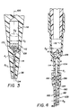
- an aspiration probe 12 comprises a narrow cavity or passageway 14 that leads from an aperture 34 at end 36, to a mixing cavity 18 having a significantly wider inside diameter than that of cavity 14.
- a transition region 28 with relatively sharp demarcations is provided between the two diameters.
- a partial vacuum is applied at passageway 40 to aspirate first a liquid 44, and then a second liquid 54, into cavity 18, with or without a bubble (not shown) between them.
- the first time both liquids are moved from passageway 14 into cavity 18 fails to produce complete mixing, since the two liquids still remain separated.
- the number of oscillations can be reduced to as few as three, by simply forcing most of the liquid to flow past the transition zone 128 each time. This, in turn, is ensured by forcing most of both liquids to flow from one cavity adjacent the transition zone, into the other cavity so adjacent, and then back.
- "most of the liquids" being moved means, at least 90% of the liquids.
- a probe preferably in the form of a disposable tip 112 is constructed substantially the same as that of the prior art, with a narrower cavity 114 leading to a wider cavity 118 connected to the narrower one by a transition zone 128.
- a common axis of symmetry 100 preferably extends through both cavities.
- the transition zone is defined by relatively sharp edges 134 and 136 at the junction with the respective cavities. "Relatively sharp" means, having a radius of curvature at the junction that is less than 25 microns. Any radii greater than that tend to produce a smooth transition between zone 128 and the respective cavities.
- a smooth transition through the use of such greater radii of curvature is preferred, but not essential, as such a smooth transition gives better results when blood agglutination for blood typing is the goal of the mixing. That is, the smooth transition using greater radii of curvature is less likely to cause the agglutinates to be broken up, all other things such as bulk flow rates, being equal.
- An example of a smooth transition using such greater radii of curvature is shown in Fig. 4.
- R 1 and R 2 for Fig. 4 can be, respectively, 1.2 mm each.
- a first liquid 144 is aspirated into cavity 114, followed by an air bubble 160. Thereafter, second liquid 154 is aspirated in so that both are still in cavity 114, Fig. 2A.
- Transition zone 128 produces sufficient rotation, arrows 170, of the liquids as to start them to mix. As shown in Fig. 1, however, just this step is not enough.
- most and preferably all of the liquids are ejected from cavity 118 past transition zone 128 and into cavity 114, arrows 172, Fig. 2C. Still further, the process is repeated, phantom arrows 174, until complete mixing has occurred. Depending on the liquids involved, only three passages from cavity 114 into cavity 118 may be necessary for complete mixing, although more can be used.
- Fig. 3 illustrates certain preferred parameters for optimal mixing in general.
- Probe 112 has an aperture 134 and an exterior surface 136 adjacent to that aperture, similar to that of the prior art.
- the cross-sectional flow-through area A 2 of cavity 118, provided by inside diameter D 2 is preferably no smaller than nine times that of the cross-sectional flow-through area A 1 provided by inside diameter D 1 , of cavity 114.
- the diameters D 1 and D 2 are generally constant so that their respective cavities are cylindrical.
- D 2 is preferably at least equal to three times D 1 .
- D 1 and D 2 include, e.g., 0.8 mm and 3.2 mm, respectively, for use with a total height H 2 , Fig. 5, of about 3 mm.
- the wall surface of at least cavity 118, and optionally also cavity 114 is selected from materials that are easily wetted by the liquids in question, that is, produce a low contact angle at the meniscus.
- the materials used for the surfaces are a function of the liquids to be mixed, as is well-known.
- the capillary number for the system does not exceed 0.001, where capillary member, as is conventional, equals liquid velocity of movement, arrow 170, divided by surface tension of the liquid mixture.
- an air bubble can be present to avoid contamination.
- An oil shield can be used as in the '305 patent, or alternatively, probe 112 can be wiped off before aspirating the second liquid.
- the capillary number can be larger, but preferably not exceeding 0.01, since above that, the movement of the liquids between cavities can product "tails" of liquid remaining in the exit cavity that delay or even ruin the mixing process.
- the size or volume of the bubble must be less than that which will prevent mixing of the liquids as they flow past the transition zone.
- the air bubble must not be so large that, after aspiration of the probe contents into cavity 118, Fig. 3, the bubble (not shown in Fig. 3) continues to totally separate the two liquids - that is, has a diameter equal to the inside diameter of cavity 118.
- the bubble volume must be less than ⁇ (D 2 ) 3 /6.
- the flow velocity in either direction past the transition zone 128 is preferably that which provides a shear rate along the wall which does not exceed about 20 sec -1 .
- This is also a function of the viscosity of the liquids, of the diameters D 1 , D 2 , and of angle alpha.
- the embodiment of Fig. 3 can also be used by coating either cavity 114 or 118 in dry form, with the reagent that is to react with the body liquid, so that only one liquid namely the body liquid, need be aspirated in at aperture 134.
- the agglutinating reagent solution can be provided during manufacturing by coating either or both cavities 114 or 118. This coating is then redissolved when the whole blood is aspirated into the appropriate cavity.
- reagents such as an antibody for an immuno-assay, may be permanently attached to the cavity walls.
- the probe it is not essential that the probe be all in one piece, or that contamination be prevented by only an oil shield or by wiping. Instead, Fig. 4, it is useful to have the probe comprise two portions, 112A and 112B one of which (112B) has an inside diameter that is different from, e.g., smaller than, at least part of the inside diameter of the other portion (112A), and which fits over the other portion adjacent aperture 134. The purpose is to allow the portion that over-fits the first portion, to cover up the exterior surface 136 adjacent to aperture 134 where residual first liquid 44 might remain. As shown, inside diameter D 3 of cavity 165 of portion 112B is substantially identical to diameter D 1 , but less than diameter D 2 , of portion 112A.
- liquid 44 is aspirated into portion 112A with portion 112B absent. Portion 112B is then mounted onto portion 112A with a sliding friction fit. At this point, liquid 44 is moved down, arrow 180, into portion 112B to the phantom position 182, leaving an amount of air at 160 to form an air bubble in the next step. That step is to move the probe of combined tip portions so as to insert only portion 112B into a bulk quantity of liquid 54 (not shown). Aspiration then causes liquid 44 at position 182, bubble 160, and an amount of the second liquid to be aspirated in the probe. When the desired amount of the second liquid is present, the probe is removed from the bulk liquid 54, and mixing proceeds as described above using repeated movement of most of the liquids past transition zone 128.
- This construction ensures both that residual first liquid amounts on portion 112A are prevented from contacting said bulk liquid 54, and that the resulting length of portions 112A and 112B are easily moldable.
- angle alpha described above is measured against the tangent line A-A drawn to a point on the wall of zone 128 that is between the definition of the wall provided by the two radii.
- cavity 118 of portion 112 or 112A has a diameter D 2 that is selected to be larger in value than the height H 2 of the total liquids aspirated thereinto, one those liquids have been moved into cavity 118.
- D 2 should be less than twice H 2 , as otherwise the volume in cavity 118 becomes so thin that it is in danger of bursting at the middle when pressure is applied to push the liquid, arrow 200, into cavity 114. Such bursting will of course prevent transfer of the liquid across the mixing transition zone.
- the probe comprises two portions, it is not essential that the inside diameter of the added-on portion equal the inside diameter of the probe portion that is covered.
- the remaining embodiments illustrate wherein, in fact, this is not the case. Parts similar to those previously described bear the same reference numeral to which the distinguishing mark ' or '' is appended.
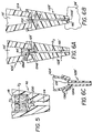
- the second portion 112B ' has an inside diameter D 3 for cavity 165 ' that is considerably smaller than inside diameter D 2 of cavity 118 ' .
- probe 112 ' is now divided into two separable portions 112A ' and 112B ' having cavities 118 ' and 165 ' which between them provide the transition zone 128 ' that causes mixing. That is, zone 128 ' is formed by an external angle alpha (shown in Fig. 5) which is 270°.
- liquid 44 ' is aspirated into portion 112A ' by itself.
- Portion 112B ' is then affixed to portion 112A ' as shown, Fig. 6A, and liquid 44 ' is pushed down into portion 112B ' , arrow 200.
- the probe is then moved so that portion 112B ' is inserted into a bulk quantity of liquid 54 ' , preferably with an air bubble 160 ' at aperture 134 ' , Fig. 6B.
- arrow 202 causes all of liquid 44 ' , bubble 160 ' , and liquid 54 ' to move through cavity 165 ' , past transition zone 128 ' , and into cavity 118 ' , thus starting mixing by rotation, arrows 170 ' .
- the oscillating movement of all the liquid via arrows 200 and 202 is then repeated as many times as is needed to complete the mixing.
- the transition zone provided by the add-on portion 112B ' when placed around exterior surface 136A ' adjacent aperture 134A ' , can be a smooth transition zone 128 ' in the manner of the embodiment of Fig. 4.
- the smaller inside diameter remains with probe portion 112B ' , rather than portion 112A ' , except where they match substantially exactly at aperture 134A ' .
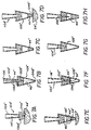
- Figs. 6A and 6B The opposite of Figs. 6A and 6B is illustrated in Figs. 7A - 7H. That is, the inside diameter of the added-on, second tip portion is substantially larger, at the transition zone, than the inside diameter of the first tip portion already used to aspirate liquid. Additionally, this embodiment illustrates that the two cavities adjacent the transition zone need not be cylindrical, but can be tapered instead along their axis of symmetry 100, Fig. 7B.
- probe portion 112A '' comprises a conical cavity 118 '' extending from an aperture 134A '' , to an upper portion 132A '' , that connects to a pump, not shown, the inside diameter of cavity 118 '' increasing with increasing distance from the aperture.
- the exterior surface 136A '' adjacent to aperture 134A '' is enlarged, also with a tapered shape, such as by securing a cork collar to the rest of the portion 112A '' .
- the inside diameter at aperture 134A '' is relatively small, e.g., about 1 mm.
- the second probe portion 112B '' has an upper portion 132B '' shaped to frictionally mate with surface 136A '' , that is, with an enlarged inside diameter.
- Portion 112B '' tapers down to a lower portion at aperture 134B '' producing a cavity 165 '' having an inside diameter that is greatly reduced from said enlarged inside diameter, and in fact, preferably is about the same as that of aperture 134A '' .
- portion 112A '' by itself is inserted into a bulk quantity of liquid 44 '' and an aliquot is aspirated, Fig. 7A.
- probe portion 112B '' is fitted over the surface 136A '' of the collar, Fig. 7B.
- liquid 44 '' is pushed or ejected from portion 112A '' into the cavity of portion 112B '' , Fig. 7C.
- the combined probe has aperture 134B '' of portion 112B '' inserted into a bulk quantity of liquid 54 '' , and that and an air bubble 160 '' , Fig. 7E, is aspirated into cavity 165 '' .
- Figs. 7F - 7H all of the liquid is aspirated and ejected back and forth past the transition zone created by the narrower inside diameter at aperture 134A '' .
- Fig. 7F it is first drawn into cavity 118 '' , arrow 202 '' , to produce the condition shown in Fig. 7G. It is then ejected back into cavity 165 '' , Fig. 7H, arrow 200 '' , so that rotational mixing occurs. This process is repeated as necessary, until the two liquids become homogeneous, or as homogenous as is possible, given the nature of the liquids.
- probe 112 ''' comprises an upper portion or cavity 118 ''' that is mounted onto the permanent probe (Fig. 4), and a lower cavity 114 ''' integrally connected to cavity 118 ''' by a transition zone wall 128 ''' , the inside diameter D 2 of cavity 118 being larger than D 1 , and preferably at least equal to three times D 1 .
- An additional cavity 165 is provided at exterior portion 136 ''' of cavity 114, with aspiration occurring at arrow 210, also as described for Fig. 4.
- cavity 165 ''' is integrally connected to cavity 114 ''' in that all 3 cavities are formed from a common wall, preferably one that is molded.
- inside diameter D 3 of cavity 165 ''' is significantly larger than inside diameter D 1 , creating a transition zone 220 not present in the embodiment of Fig. 4.
- the value of D 3 is selected to cause rotational mixing when most, and preferably all, of the liquids aspirated into tip 112 ''' , is moved from cavity 114 ''' into cavity 165 ''' past transition zone 220.
- D 3 ' is most preferably at least equal to three times D 1 .
- D 3 can be the same as or different from D 1 .
- the inside diameter of cavity 165 ''' can be narrowed to D 3 '' at the end into which liquid is first aspirated, arrow 210.
- cavity 165 ''' of tip 112 ''' can be formed by the wall of tip portion 112B ''' , removable as in the embodiment of Fig. 4, so that portion 112B ''' can be added after the first liquid is aspirated, and portion 112B ''' covers any first liquid remaining on exterior surface 136 ''' .
- Aspiration of a second liquid then occurs as shown by arrow 210 ''' , Fig. 9.
- inside diameter D 3 ' at the junction of the cavities 114 ''' and 165 ''' is greater than the inside diameter D 1 , rather than equal thereto as in Fig.
- D 3 ' at the transition zone equals D 1 + twice the value of T, where "T" is the thickness of the wall providing exterior surface 136 ''' .
- D 3 ' may or may not be at least equal to three times D 1 , depending on the value of T.
- the inside diameter of cavity 165 ''' can be narrowed to D 3 '' a the end into which liquid is first aspirated.
- Figs. 8 and 9 It is the embodiments of Figs. 8 and 9 that have proven to be most efficient in mixing, that is, in producing complete mixing in the fewest cycles of repeated back and forth movement past the transition zones.
- the embodiment of Fig. 9 produced complete mixing of two liquids totaling 20 microliters in only 7.5 cycles of such back and forth movement, at a flow rate of 50 microliters per sec., in about 10 sec.
- a preferred use of this mixing action is to produce sufficient blood cell agglutination as to allow blood typing.
- one of the liquids is, of course, whole blood and the other is a solution of agglutinating reagent, aspirated into the tip, in either order. Any such solution can be used.
- a highly preferred example comprises a 3% bovine serum albumin in a 0.1 molar phosphate buffered saline solution containing anti-B IgM clones formulated from tissue culture supernatant (1, 20, and 31 ⁇ g/ml concentrations) plus 0.004% FD&C blue dye number 1. All concentrations are % by weights.
- this detection is preferably done by scanning for absorbance or light scattering at a position in narrower tip portion 114 '' .
- an appropriate optics such as a conventional fiber optics is used to deliver light of a predetermined wavelength that is then transmitted into the tip.
- the amount of light that is absorbed, measured approximately 10 minutes after mixing has been completed, is then detected as shown schematically by arrow 302, or the amount of light scattered is detected as shown by arrow 304.
- suitable wavelengths include 540 nm, and/or 830 nm. The former is particularly useful since that is the peak absorption of hemoglobin. Detection of the amount of light scattered, as at 304, is particularly useful to avoid interference from any hemolysis.
- Figs. 10 and 11 illustrate the method using absorbance and an illuminating wavelength of 540 nm.
- the liquid is passed down from portion 118 ''' to portion 114 ''' , after 10 minutes have passed after it has been mixed sufficiently.
- the amount of absorbance rises from zero due to the passage of air.
- only liquid is passed by the scanner, and the first part of that liquid is very absorbent, regardless of whether the reaction is negative, weak, or strong.
- the results deviate depending on the amount of agglutination achieved.
- a strong reaction clumps the red cells so well that after about 65%, the volume is essentially free of cells and is clear.
- a weak reaction has less absorption, but still much more than the strong, after 65% of the volume scanned.
- the liquid can be moved upward from portion 165 ''' into narrower portion 114 ''' and on upward into portion 118 ''' , to do the scanning.
- the results are shown in Fig. 11. Differentiation of the results occurs when from zero to 18% of the volume has been scanned. That is, the first portion to flow past the scanner is the liquid portion free of red cells, in the event of a strong reaction, because almost all of the cells have coagulated together. But in the case of the weak reaction, some red cells are still unagglutinated and remain in that first portion of the volume, as shown by the middle curve of Fig. 11.
- Agglutination caused by a coagulating reagent allows separation of the cellular fraction of whole blood from the plasma, to occur in the tip. That is, when the agglutinating reagent is selected from conventional coagulating reagents such as a polyelectrolyte, eg, polylysine, or an antibody such as anti-glycophorin, the mixing within the tip as described above will not only cause coagulation of all the red cells, but it will also lead to a physical separation of those coagulated cells from the plasma.
- conventional coagulating reagents such as a polyelectrolyte, eg, polylysine, or an antibody such as anti-glycophorin
- the cells settle to the bottom of the tip, e.g., tip portion or cavity 165 ''' of Fig. 9. At this juncture, those cells can then be expelled by dispensing them out of the orifice of the tip, leaving only plasma remaining behind. That plasma can then be dispensed onto a suitable platform for testing, for example, into a well or cup adapted for immunoassay, such as is described in US Pat. No. 5,441,895.
- a probe was constructed having two capillaries with different inner diameters.
- the smaller capillary had an inner diameter of 0.557 mm.
- the larger capillary had an inner diameter of 2.29 mm.
- the length of the smaller capillary was 41 mm, which holds up to 10 micro-liter of fluid.
- the larger capillary had a length of 30 mm.
- a type B blood of 4 micro-liters was aspirated from the bottom end of the small capillary by the pump.
- the pump then continued to withdraw 1 micro-liters of air in the small capillary.
- 4 micro-liters of the agglutinating reagent described above was aspirated thereafter and the air bubble separated the two liquids in the smaller capillary.
- the pump was then driven to move all the fluids across the transition zone between the small and large capillary with a flow rate of 0.5 micro-liter/second. Once in the larger capillary, a spherical air bubble was created by the surface tension, and the two liquids started to encounter and mix. As the pump drove the fluids to flow down into the smaller capillary with a flow rate of 0.5 micro-litter/second, the bubble was eliminated.
- the mixture of the two fluids was oscillated between the two capillaries with a constant flow rate of 0.5 micro-liters/second.
- the agglutinated structure formation was visible at the end of the first cycle of this motion.
- Phase separation was very significant at the end of the second cycle in the small capillary, with clear supernatant in the up portion and the agglutinated cell structure in the bottom portion. Some very small agglutinated cells were still visible in the supernatant at this stage.
- the phase separation was completed by the end of the third cycle, with almost zero cell structure left in the supernatant.
- the total time period for the three cycles was 2 minutes. Weaker reactions can be expected to take longer.
- one method of doing this is to make a visual observation of light transmittance through the mixture to determine the amount of agglutination within a fixed time of the agglutination reaction. A chart is used for comparison, and the user estimates the blood type from the amount of clumping or agglutination observed in whichever probe portion that the combined liquids are in at the time.
- a probe was constructed similar to shown in Fig. 9, except that the tip portion 165 ''' was cut off at line C ⁇ C to create a cone-shaped tip portion having an inside diameter at D 3 of about 2.54 mm, and at cut line C ⁇ C of about 1 mm, with a cone angle of about 20 degrees and a length of 10 mm.
- Tip portion 114 ''' had a length of about 15 mm and an inside diameter D 1 of about 1 mm.
- Tip portion 118 '''' had a diameter D 2 of about 4.7 mm Blood in an amount of 10 microliters was aspirated into the entire tip ensemble through cone portion 165 ''' , after which the cone was wiped clean.
Landscapes
- Chemical & Material Sciences (AREA)
- Chemical Kinetics & Catalysis (AREA)
- Health & Medical Sciences (AREA)
- General Health & Medical Sciences (AREA)
- Immunology (AREA)
- Life Sciences & Earth Sciences (AREA)
- Analytical Chemistry (AREA)
- Biochemistry (AREA)
- Clinical Laboratory Science (AREA)
- General Physics & Mathematics (AREA)
- Physics & Mathematics (AREA)
- Pathology (AREA)
- Investigating Or Analysing Biological Materials (AREA)
- Sampling And Sample Adjustment (AREA)
- Automatic Analysis And Handling Materials Therefor (AREA)
- Analysing Materials By The Use Of Radiation (AREA)
- Degasification And Air Bubble Elimination (AREA)
Abstract
Description
the improvement wherein the capillary number resulting from the mixing in step c) does not exceed about 0.01, the capillary number being defined as the ratio of liquid velocity times viscosity and surface tension, so that any tails formed during the mixing step c) are minimized.
wherein the transition zone of the one cavity is formed by a variance of the inside diameter that increases in value as the middlemost cavity is transited outward into either of the other two end cavities.
Claims (28)
- A method of mixing a plurality of liquids comprising the steps of:a) providing a probe tip with an internal cavity having a plurality of different inside diameters;b) providing by aspiration a plurality of liquids inside a portion of the probe tip; andc) moving at least most of said liquids back and forth at least several times between a part of said cavity with a smaller inside diameter and a part with a larger inside diameter, said larger and smaller diameters being sufficient to provide a sufficient rotation of liquid at it moves between diameters to cause mixing of said liquids;
wherein the capillary number resulting from the mixing in said step c) does not exceed about 0.01, said capillary number being defined as the ratio of liquid velocity times viscosity and surface tension, so that any tails formed during said mixing step c) are minimized. - The method of claim 1, wherein the capillary number of step c) does not exceed about 0.001, so that any entrained air bubble is more readily removed from said liquids as they are mixed.
- The method of claim 2, wherein said any bubble is aspirated into said probe tip inbetween said plural liquids, with a volume that is less than that which prevents mixing of the liquids in the part of said cavity having the larger of said inside diameters.
- A method of mixing a plurality of liquids comprising the steps of:a) providing a probe tip with an internal cavity having a plurality of different inside diameters;b) providing by aspiration a plurality of liquids inside a portion of the probe tip; andc) moving at least most of said liquids back and forth at least several times between a part of said cavity with a smaller inside diameter and a part with a larger inside diameter, said larger and smaller diameter being sufficient to provide a sufficient rotation of liquid as it moves between diameters to cause mixing of said liquids;
wherein said cavity parts comprise two separate but matable tip portions, and said method further includes the step of mounting a mountable tip portion of one of said inside diameters onto said tip portion of the other inside diameter inbetween aspiration of liquids, such that carry-over contamination between liquids is prevented. - The method of claim 4, further including the steps of removing said tip portion after each additional liquid is aspirated and attaching a new tip portion before aspirating into said probe tip an additional liquid.
- The method of claim 4 or claim 5, wherein said mountable tip portion has a larger inside diameter than that of said tip portion on which it is mounted.
- The method of claim 6, wherein said tip portion on which said mountable portion is mounted further includes two inside diameters of significantly different values, so that flow of said liquids past a demarcation zone between said differently valued inside diameters also provides rotational mixing of the liquids.
- The method of claim 7, wherein the larger of said different valued inside diameters is at least as large as the largest inside diameter of said mountable tip portion.
- The method of any one of claims 6 to 8, wherein the largest of said inside diameter of said mountable tip portion or said larger of said differently valued diameters is at least equal to three times the value of the smaller of said differently valued inside diameters.
- A method of mixing a plurality of liquids comprising the steps of:a) providing a probe tip with an internal cavity having a plurality of different inside diameters;b) providing by aspiration a plurality of liquids inside a portion of the probe tip; andc) moving at least most of said liquids back and forth at least several times between a part of said cavity with a smaller inside diameter and a part with a larger inside diameter, said larger and smaller diameter being sufficient to provide a sufficient rotation of liquid as it moves between diameters to cause mixing of said liquids;
wherein said inside diameters are each a measure of a cross-sectional flow-through area of said cavity part, and the cross-sectional flow-through areas of said cavity part, and the cross-sectional flow-through area of said larger inside diameter is at least three times the cross-sectional flow through area of said smaller inside diameter. - The method of any one of claims 1 to 10 wherein said one liquid is whole blood and wherein said moving step causes only mixing such that cells that have agglutinated are less likely to break apart.
- A method of mixing a plurality of liquids comprising the steps of:a) providing a probe tip with an internal cavity having a plurality of different inside diameters;b) providing by aspiration a plurality of liquids inside a portion of the probe tip; andc) moving at least most of said liquids back and forth at least several times between a part of said cavity with a smaller inside diameter and a part with a larger inside diameter, said larger and smaller diameters being sufficient to provide a sufficient rotation of liquid at it moves between diameters to cause mixing of said liquids;
wherein said larger inside diameter is obtained by i) selecting as a first tip portion a tapered tip at least a portion of which has an inside diameter that is much larger than the smaller inside diameter of the probe tip, and ii) joining said tapered tip to said probe tip having the smaller inside diameter using a joining collar mounted around said tip portion of step b). - A method of mixing a plurality of liquids comprising the steps of:a) providing a probe tip with an internal cavity having a plurality of different inside diameters;b) providing by aspiration a plurality of liquids inside a portion of the probe tip; andc) moving at least most of said liquids back and forth at least several times between a part of said cavity with a smaller inside diameter and a part with a larger inside diameter, said larger and smaller diameters being sufficient to provide a sufficient rotation of liquid at it moves between diameters to cause mixing of said liquids;
wherein the total amount of liquid provided by said step b) is such that if all liquid is moved into said part with the larger inside diameter, the larger inside diameter is greater than the height of the total moved liquid, but less than twice the height of the total moved liquid, so that mixing as per step c) is maximized. - The method of claim 12 or claim 13 wherein said mixing is accomplished without any substantial agitation or shaking of the probe tip.
- A method of mixing a plurality of liquids comprising the steps of:a) providing a probe tip with an internal cavity having a plurality of different inside diameters;b) providing by aspiration a plurality of liquids inside a portion of the probe tip; andc) moving at least most of said liquids back and forth at least several times between a part of said cavity with a smaller inside diameter and a part with a larger inside diameter, said larger and smaller diameters being sufficient to provide a sufficient rotation of liquid at it moves between diameters to cause mixing of said liquids;
wherein said step c) comprises moving at least most of the liquids back and forth at least between said cavity part with said smaller inside diameter and a part of said cavity of a larger inside diameter located at opposite ends of said cavity part of said smaller inside diameter, so that mixing efficiency is enhanced by rotation of the liquid as it moves past said opposite ends, rather than a single end of said smaller inside diameter cavity part. - The method of claim 15, wherein said liquids are completely mixed within 7.5 repetitions of said movement back and forth at a flow rate of about 50 microliters per second, within about 10 seconds.
- A probe tip, for mixing liquids within the tip after aspiration of the liquids thereinto, said tip comprising:a wall defining 3 connected cavities of unequal inside diameters, one of the compartments being sandwiched as a middle compartment between the other two which form end compartments, each two adjacent cavities being connected by a transition zone wall and said inside diameters being sufficiently unequal in said adjacent 2 cavities as to cause rotational mixing of liquids as they move past said transition zone wall;
wherein said transition zone of the one cavity is formed by a variance of said inside diameters that increases in value as the middlemost cavity is transited outward into either of said other two end cavities. - The probe of claim 17, wherein one of said end cavities is defined by a wall portion removably mounted on a wall defining said middle cavity.
- A probe of claim 17 or claim 18, wherein the inside diameter of at least one of said end cavities is at least equal to three times the value of the smaller of said differently valued inside diameters.
- A method of determining the strength of an agglutination reaction within a hollow container comprising walls capable of transmitting light at certain predetermined wavelengths comprising the steps of:a) providing a mixture of a sample and an agglutinating reagent within a first cavity having a first inside diameter,b) transferring the mixture to a second cavity having a second inside diameter substantially smaller than said first inside diameter,c) scanning the liquid within said second cavity during said step b) with a beam of light at said predetermined wavelengths, said 10% portion being that portion closest to said first cavity;d) after said scanning step c), detecting the amount of light absorbed within or scattered by said 10% portion by said beam,e) transferring said mixture back into said first cavity,f) repeating steps b)-d) at least once until some agglutinated material has separated from non-agglutinated material, andg) calculating the amount of agglutination from the absorbance or scattering detected in said step d).
- The method of claim 20, wherein said transfer step moves the liquid down from the first cavity to said second cavity, so that gravity assists in said separation of step f).
- The method of claim 20 or claim 21, wherein said step g) comprises determining what percentage of the total possible absorbance is detected at a preselected percent of the volume scanned that is indicative of agglutinating reactions, as an indication of the %, and therefore the strength, of the agglutination that has occurred.
- The method of anyone of claims 20 to 22, wherein said detecting step d) uses radiation at about 540 nm, the peak absorption wavelength of hemoglobin.
- The method of any one of claims 20 to 23, wherein said step d) comprises detecting the amount of scattered radiation, so that any hemolysis interference is avoided.
- A method of agglutinating blood cells in whole blood, comprising the steps of:a) aspirating whole blood into a disposable tip mounted on a probe, said tip having at least two portions with significantly different inside diameters, connected to each other by a transition zone,b) aspirating into the same tip thereafter, an agglutinating reagent, andc) moving said blood and reagent back and forth as a total liquid, first entirely into one of said portions and then entirely into the other of said portions, a sufficient number of times so as to cause coagulation of the cells of the whole blood, and then subsequent separation of plasma from the coagulated cells.
- The method of claim 25, wherein said cells are allowed to settle adjacent to an exit orifice of said tip, and d) thereafter, dispensing said cells out of said tip, leaving only plasma remaining therein.
- The method of claim 26, further comprising the step of e) dispensing at least a portion of said remaining plasma from said tip into a reaction well adapted for carrying out an immunoassay of the plasma.
- The method of any one of claims 25 to 27, wherein said agglutinating reagent is a polyelectrolyte or an antibody.
Priority Applications (1)
| Application Number | Priority Date | Filing Date | Title |
|---|---|---|---|
| EP06075373A EP1666889B1 (en) | 1999-02-12 | 2000-02-11 | Method for agglutinating blood cells within a probe tip |
Applications Claiming Priority (2)
| Application Number | Priority Date | Filing Date | Title |
|---|---|---|---|
| US11980799P | 1999-02-12 | 1999-02-12 | |
| US119807P | 1999-02-12 |
Related Child Applications (1)
| Application Number | Title | Priority Date | Filing Date |
|---|---|---|---|
| EP06075373A Division EP1666889B1 (en) | 1999-02-12 | 2000-02-11 | Method for agglutinating blood cells within a probe tip |
Publications (3)
| Publication Number | Publication Date |
|---|---|
| EP1027932A2 true EP1027932A2 (en) | 2000-08-16 |
| EP1027932A3 EP1027932A3 (en) | 2001-04-18 |
| EP1027932B1 EP1027932B1 (en) | 2007-07-25 |
Family
ID=22386538
Family Applications (2)
| Application Number | Title | Priority Date | Filing Date |
|---|---|---|---|
| EP06075373A Expired - Lifetime EP1666889B1 (en) | 1999-02-12 | 2000-02-11 | Method for agglutinating blood cells within a probe tip |
| EP00301086A Expired - Lifetime EP1027932B1 (en) | 1999-02-12 | 2000-02-11 | Method for determining the strength of an agglutination reaction |
Family Applications Before (1)
| Application Number | Title | Priority Date | Filing Date |
|---|---|---|---|
| EP06075373A Expired - Lifetime EP1666889B1 (en) | 1999-02-12 | 2000-02-11 | Method for agglutinating blood cells within a probe tip |
Country Status (4)
| Country | Link |
|---|---|
| EP (2) | EP1666889B1 (en) |
| JP (2) | JP2000304754A (en) |
| AT (2) | ATE367863T1 (en) |
| DE (2) | DE60044983D1 (en) |
Cited By (8)
| Publication number | Priority date | Publication date | Assignee | Title |
|---|---|---|---|---|
| WO2004011913A3 (en) * | 2002-07-26 | 2004-06-10 | Ortho Clinical Diagnostics Inc | Metering tip with internal features to control fluid meniscus and fluid oscillation |
| DE102004046740A1 (en) * | 2004-06-07 | 2005-12-29 | Aviso Gmbh Mechatronic Systems | Tool head for a device for the automatic isolation and treatment of cell clones |
| EP1977831A3 (en) * | 2007-03-20 | 2008-10-22 | Hitachi High-Technologies Corporation | Dispensing nozzle tip |
| EP2343129A1 (en) * | 2010-01-11 | 2011-07-13 | Baxter International Inc. | Pipette system, pipette tip assembly and kit |
| EP3076156A1 (en) * | 2015-03-31 | 2016-10-05 | Commissariat à l'Énergie Atomique et aux Énergies Alternatives | Method for determining the particle agglutination level in a sample |
| CN113441199A (en) * | 2021-06-23 | 2021-09-28 | 上海市第十人民医院 | Sample adding gun for automatically removing bubbles in sample adding sample |
| CN113447682A (en) * | 2021-07-07 | 2021-09-28 | 核工业西南物理研究院 | Probe needle head and electrostatic probe |
| US12427512B2 (en) | 2019-09-03 | 2025-09-30 | Kyocera Corporation | Pipette |
Families Citing this family (14)
| Publication number | Priority date | Publication date | Assignee | Title |
|---|---|---|---|---|
| JP2005249535A (en) * | 2004-03-03 | 2005-09-15 | Olympus Corp | Dispensation probe and autoanalyzer equipped therewith |
| DE102004050466A1 (en) * | 2004-10-16 | 2006-04-20 | Olympus Diagnostica Lab Automation Gmbh | Device for pipetting |
| JP2006349638A (en) * | 2005-06-20 | 2006-12-28 | Fujifilm Holdings Corp | Method and apparatus for homogenizing trace quantity of liquid |
| JP2007322148A (en) * | 2006-05-30 | 2007-12-13 | Hitachi High-Tech Science Systems Corp | Dispensing tube and analyzer using the same |
| JP2009109459A (en) * | 2007-11-01 | 2009-05-21 | Konica Minolta Medical & Graphic Inc | Pipette chip, inspection system, pipette, and filling apparatus |
| US7850917B2 (en) * | 2008-03-11 | 2010-12-14 | Ortho-Clinical Diagnostics, Inc. | Particle agglutination in a tip |
| JP5284928B2 (en) * | 2009-11-20 | 2013-09-11 | 株式会社日立ハイテクノロジーズ | Liquid mixing method and dispensing device |
| JP2013007579A (en) * | 2011-06-22 | 2013-01-10 | Seiko Epson Corp | Dispensation method |
| JP5783200B2 (en) * | 2013-03-22 | 2015-09-24 | 東亜ディーケーケー株式会社 | Two-stage reaction system, sample liquid measurement system, and sample liquid measurement method |
| CN107209195B (en) * | 2015-02-25 | 2018-10-16 | 株式会社日立高新技术 | Automatic analysis device |
| JP6825889B2 (en) * | 2016-11-29 | 2021-02-03 | 京セラ株式会社 | Nozzle for biochemical sampling |
| JP7091829B2 (en) * | 2017-11-17 | 2022-06-28 | 住友金属鉱山株式会社 | Solution mixing method |
| CN111624085B (en) * | 2020-07-29 | 2020-10-23 | 天津中新科炬生物制药股份有限公司 | Sample diluting device and reagent card for detecting novel coronavirus antibody |
| EP4700391A1 (en) * | 2024-08-22 | 2026-02-25 | Hombrechtikon Systems Engineering AG | Method for mixing fluids, and pipetting device |
Family Cites Families (9)
| Publication number | Priority date | Publication date | Assignee | Title |
|---|---|---|---|---|
| EP0005979A1 (en) * | 1978-05-25 | 1979-12-12 | Dynatech Ag | A miniature reaction container and a method and apparatus for introducing micro volumes of liquid to such a container |
| US4347875A (en) | 1980-07-14 | 1982-09-07 | Eastman Kodak Company | Self-cleaning nozzle construction for aspirators |
| DE3541057A1 (en) * | 1985-11-19 | 1987-05-21 | Kratzer Michael | METHOD AND DEVICE FOR MEASURING THE AGGREGATION OF BLOOD PLATES OR THE COAGULATION OF THE BLOOD |
| US4902624A (en) * | 1987-11-23 | 1990-02-20 | Eastman Kodak Company | Temperature cycling cuvette |
| JP2839560B2 (en) * | 1989-07-10 | 1998-12-16 | 株式会社日立製作所 | Particle suspension mixing device, particle suspension mixing method, and particle measuring device |
| US5441895A (en) | 1993-12-07 | 1995-08-15 | Jakubowicz; Raymond F. | Reagent cup shape allowing stacking without dislodging reagent |
| DE4420900A1 (en) * | 1994-06-15 | 1995-12-21 | Boehringer Mannheim Gmbh | Procedure for the repeated removal of liquids |
| US5773305A (en) * | 1996-05-02 | 1998-06-30 | Bayer Corp. | Sample dilution module |
| DE19652784A1 (en) * | 1996-12-19 | 1998-06-25 | Dade Behring Marburg Gmbh | Device (cuvette) for holding and storing liquids and for carrying out optical measurements |
-
2000
- 2000-02-10 JP JP2000038177A patent/JP2000304754A/en active Pending
- 2000-02-11 AT AT00301086T patent/ATE367863T1/en not_active IP Right Cessation
- 2000-02-11 EP EP06075373A patent/EP1666889B1/en not_active Expired - Lifetime
- 2000-02-11 EP EP00301086A patent/EP1027932B1/en not_active Expired - Lifetime
- 2000-02-11 DE DE60044983T patent/DE60044983D1/en not_active Expired - Lifetime
- 2000-02-11 AT AT06075373T patent/ATE481168T1/en not_active IP Right Cessation
- 2000-02-11 DE DE60035628T patent/DE60035628T2/en not_active Expired - Lifetime
-
2009
- 2009-05-25 JP JP2009125512A patent/JP2009241066A/en active Pending
Cited By (12)
| Publication number | Priority date | Publication date | Assignee | Title |
|---|---|---|---|---|
| WO2004011913A3 (en) * | 2002-07-26 | 2004-06-10 | Ortho Clinical Diagnostics Inc | Metering tip with internal features to control fluid meniscus and fluid oscillation |
| DE102004046740A1 (en) * | 2004-06-07 | 2005-12-29 | Aviso Gmbh Mechatronic Systems | Tool head for a device for the automatic isolation and treatment of cell clones |
| DE102004046740B4 (en) * | 2004-06-07 | 2006-07-06 | Aviso Gmbh Mechatronic Systems | Tool head for a device for the automatic isolation and treatment of cell clones |
| EP1977831A3 (en) * | 2007-03-20 | 2008-10-22 | Hitachi High-Technologies Corporation | Dispensing nozzle tip |
| US8293192B2 (en) | 2007-03-20 | 2012-10-23 | Hitachi High-Technologies Corporation | Dispensing nozzle tip |
| EP2343129A1 (en) * | 2010-01-11 | 2011-07-13 | Baxter International Inc. | Pipette system, pipette tip assembly and kit |
| EP3076156A1 (en) * | 2015-03-31 | 2016-10-05 | Commissariat à l'Énergie Atomique et aux Énergies Alternatives | Method for determining the particle agglutination level in a sample |
| US10054587B2 (en) | 2015-03-31 | 2018-08-21 | Commissariat A L'energie Atomique Et Aux Energies Alternatives | Method for determining the level of agglutination of particles in a sample |
| US12427512B2 (en) | 2019-09-03 | 2025-09-30 | Kyocera Corporation | Pipette |
| CN113441199A (en) * | 2021-06-23 | 2021-09-28 | 上海市第十人民医院 | Sample adding gun for automatically removing bubbles in sample adding sample |
| CN113447682A (en) * | 2021-07-07 | 2021-09-28 | 核工业西南物理研究院 | Probe needle head and electrostatic probe |
| CN113447682B (en) * | 2021-07-07 | 2022-11-08 | 核工业西南物理研究院 | Probe needle head and electrostatic probe |
Also Published As
| Publication number | Publication date |
|---|---|
| ATE481168T1 (en) | 2010-10-15 |
| EP1027932A3 (en) | 2001-04-18 |
| HK1028364A1 (en) | 2001-02-16 |
| JP2000304754A (en) | 2000-11-02 |
| EP1666889A2 (en) | 2006-06-07 |
| ATE367863T1 (en) | 2007-08-15 |
| EP1666889B1 (en) | 2010-09-15 |
| JP2009241066A (en) | 2009-10-22 |
| DE60035628T2 (en) | 2008-05-21 |
| DE60044983D1 (en) | 2010-10-28 |
| DE60035628D1 (en) | 2007-09-06 |
| EP1027932B1 (en) | 2007-07-25 |
| EP1666889A3 (en) | 2006-09-13 |
Similar Documents
| Publication | Publication Date | Title |
|---|---|---|
| EP1666889B1 (en) | Method for agglutinating blood cells within a probe tip | |
| US7452508B2 (en) | Aspirating and mixing of liquids within a probe tip | |
| US6641993B1 (en) | Aspirating and mixing of liquids within a probe tip | |
| AU725620B2 (en) | Sample dilution module | |
| US4659677A (en) | Method providing liquid mixing outside containers | |
| US4845025A (en) | Biological sample mixing apparatus and method | |
| EP0408270B1 (en) | Pipetter, pipette tube, sample analyzing apparatus including them and method of mixing and pipetting liquids | |
| US7787116B2 (en) | Cuvette | |
| EP0100663B1 (en) | Dilution cups for spectrophotometer analyzer | |
| JP4474099B2 (en) | Liquid storage container and cartridge | |
| US20090162885A1 (en) | Systems and methods for measuring fluid properties | |
| JPH07239334A (en) | Liquid mixing method | |
| JPS61169736A (en) | Liquid pipet device and pipet method | |
| US7517694B2 (en) | Metering tip with internal features to control fluid meniscus and oscillation | |
| US6426048B1 (en) | Sample dilution module with offset mixing chamber | |
| CN101393223A (en) | Specimen analyzer and liquid suction assembly | |
| US8186869B2 (en) | Method and device for dosing and mixing small amounts of liquid | |
| HK1028364B (en) | Method for determining the strength of an agglutination reaction | |
| JP2005043361A (en) | Improved fluid mixture in analyzer for diagnosis | |
| JP2004519685A (en) | Liquid sample dispensing method for precise liquid delivery without crossover | |
| JP2001514732A (en) | Means and method for cleaning a reaction vessel | |
| CA1229826A (en) | Device and method providing liquid mixing outside containers | |
| JP3952182B2 (en) | Liquid level detection method in dispenser | |
| AU624103B2 (en) | Biological sample mixing apparatus and method | |
| WO2025164287A1 (en) | Inspection device |
Legal Events
| Date | Code | Title | Description |
|---|---|---|---|
| PUAI | Public reference made under article 153(3) epc to a published international application that has entered the european phase |
Free format text: ORIGINAL CODE: 0009012 |
|
| AK | Designated contracting states |
Kind code of ref document: A2 Designated state(s): AT BE CH CY DE DK ES FI FR GB GR IE IT LI LU MC NL PT SE |
|
| AX | Request for extension of the european patent |
Free format text: AL;LT;LV;MK;RO;SI |
|
| PUAL | Search report despatched |
Free format text: ORIGINAL CODE: 0009013 |
|
| AK | Designated contracting states |
Kind code of ref document: A3 Designated state(s): AT BE CH CY DE DK ES FI FR GB GR IE IT LI LU MC NL PT SE |
|
| AX | Request for extension of the european patent |
Free format text: AL;LT;LV;MK;RO;SI |
|
| RIC1 | Information provided on ipc code assigned before grant |
Free format text: 7B 01L 3/02 A, 7G 01N 1/38 B, 7G 01N 33/53 B, 7G 01N 33/49 B |
|
| 17P | Request for examination filed |
Effective date: 20010926 |
|
| AKX | Designation fees paid |
Free format text: AT BE CH CY DE DK ES FI FR GB GR IE IT LI LU MC NL PT SE |
|
| 17Q | First examination report despatched |
Effective date: 20050704 |
|
| GRAP | Despatch of communication of intention to grant a patent |
Free format text: ORIGINAL CODE: EPIDOSNIGR1 |
|
| RTI1 | Title (correction) |
Free format text: METHOD FOR DETERMINING THE STRENGTH OF AN AGGLUTINATION REACTION |
|
| GRAS | Grant fee paid |
Free format text: ORIGINAL CODE: EPIDOSNIGR3 |
|
| GRAA | (expected) grant |
Free format text: ORIGINAL CODE: 0009210 |
|
| AK | Designated contracting states |
Kind code of ref document: B1 Designated state(s): AT BE CH CY DE DK ES FI FR GB GR IE IT LI LU MC NL PT SE |
|
| REG | Reference to a national code |
Ref country code: GB Ref legal event code: FG4D |
|
| REG | Reference to a national code |
Ref country code: CH Ref legal event code: EP |
|
| REG | Reference to a national code |
Ref country code: IE Ref legal event code: FG4D |
|
| REF | Corresponds to: |
Ref document number: 60035628 Country of ref document: DE Date of ref document: 20070906 Kind code of ref document: P |
|
| REG | Reference to a national code |
Ref country code: CH Ref legal event code: NV Representative=s name: E. BLUM & CO. AG PATENT- UND MARKENANWAELTE VSP |
|
| REG | Reference to a national code |
Ref country code: HK Ref legal event code: GR Ref document number: 1028364 Country of ref document: HK |
|
| ET | Fr: translation filed | ||
| PG25 | Lapsed in a contracting state [announced via postgrant information from national office to epo] |
Ref country code: FI Free format text: LAPSE BECAUSE OF FAILURE TO SUBMIT A TRANSLATION OF THE DESCRIPTION OR TO PAY THE FEE WITHIN THE PRESCRIBED TIME-LIMIT Effective date: 20070725 Ref country code: ES Free format text: LAPSE BECAUSE OF FAILURE TO SUBMIT A TRANSLATION OF THE DESCRIPTION OR TO PAY THE FEE WITHIN THE PRESCRIBED TIME-LIMIT Effective date: 20071105 Ref country code: NL Free format text: LAPSE BECAUSE OF FAILURE TO SUBMIT A TRANSLATION OF THE DESCRIPTION OR TO PAY THE FEE WITHIN THE PRESCRIBED TIME-LIMIT Effective date: 20070725 Ref country code: PT Free format text: LAPSE BECAUSE OF FAILURE TO SUBMIT A TRANSLATION OF THE DESCRIPTION OR TO PAY THE FEE WITHIN THE PRESCRIBED TIME-LIMIT Effective date: 20071226 |
|
| NLV1 | Nl: lapsed or annulled due to failure to fulfill the requirements of art. 29p and 29m of the patents act | ||
| PG25 | Lapsed in a contracting state [announced via postgrant information from national office to epo] |
Ref country code: AT Free format text: LAPSE BECAUSE OF FAILURE TO SUBMIT A TRANSLATION OF THE DESCRIPTION OR TO PAY THE FEE WITHIN THE PRESCRIBED TIME-LIMIT Effective date: 20070725 |
|
| PG25 | Lapsed in a contracting state [announced via postgrant information from national office to epo] |
Ref country code: BE Free format text: LAPSE BECAUSE OF FAILURE TO SUBMIT A TRANSLATION OF THE DESCRIPTION OR TO PAY THE FEE WITHIN THE PRESCRIBED TIME-LIMIT Effective date: 20070725 |
|
| PG25 | Lapsed in a contracting state [announced via postgrant information from national office to epo] |
Ref country code: DK Free format text: LAPSE BECAUSE OF FAILURE TO SUBMIT A TRANSLATION OF THE DESCRIPTION OR TO PAY THE FEE WITHIN THE PRESCRIBED TIME-LIMIT Effective date: 20070725 Ref country code: GR Free format text: LAPSE BECAUSE OF FAILURE TO SUBMIT A TRANSLATION OF THE DESCRIPTION OR TO PAY THE FEE WITHIN THE PRESCRIBED TIME-LIMIT Effective date: 20071026 |
|
| PLBE | No opposition filed within time limit |
Free format text: ORIGINAL CODE: 0009261 |
|
| STAA | Information on the status of an ep patent application or granted ep patent |
Free format text: STATUS: NO OPPOSITION FILED WITHIN TIME LIMIT |
|
| PG25 | Lapsed in a contracting state [announced via postgrant information from national office to epo] |
Ref country code: SE Free format text: LAPSE BECAUSE OF FAILURE TO SUBMIT A TRANSLATION OF THE DESCRIPTION OR TO PAY THE FEE WITHIN THE PRESCRIBED TIME-LIMIT Effective date: 20071025 |
|
| 26N | No opposition filed |
Effective date: 20080428 |
|
| PG25 | Lapsed in a contracting state [announced via postgrant information from national office to epo] |
Ref country code: MC Free format text: LAPSE BECAUSE OF NON-PAYMENT OF DUE FEES Effective date: 20080228 |
|
| PG25 | Lapsed in a contracting state [announced via postgrant information from national office to epo] |
Ref country code: IE Free format text: LAPSE BECAUSE OF NON-PAYMENT OF DUE FEES Effective date: 20080211 |
|
| PG25 | Lapsed in a contracting state [announced via postgrant information from national office to epo] |
Ref country code: CY Free format text: LAPSE BECAUSE OF FAILURE TO SUBMIT A TRANSLATION OF THE DESCRIPTION OR TO PAY THE FEE WITHIN THE PRESCRIBED TIME-LIMIT Effective date: 20070725 |
|
| PG25 | Lapsed in a contracting state [announced via postgrant information from national office to epo] |
Ref country code: LU Free format text: LAPSE BECAUSE OF NON-PAYMENT OF DUE FEES Effective date: 20080211 |
|
| PGFP | Annual fee paid to national office [announced via postgrant information from national office to epo] |
Ref country code: IT Payment date: 20110221 Year of fee payment: 12 |
|
| PG25 | Lapsed in a contracting state [announced via postgrant information from national office to epo] |
Ref country code: IT Free format text: LAPSE BECAUSE OF NON-PAYMENT OF DUE FEES Effective date: 20120211 |
|
| PGFP | Annual fee paid to national office [announced via postgrant information from national office to epo] |
Ref country code: CH Payment date: 20140212 Year of fee payment: 15 |
|
| PGFP | Annual fee paid to national office [announced via postgrant information from national office to epo] |
Ref country code: FR Payment date: 20140211 Year of fee payment: 15 |
|
| PGFP | Annual fee paid to national office [announced via postgrant information from national office to epo] |
Ref country code: GB Payment date: 20140206 Year of fee payment: 15 |
|
| PGFP | Annual fee paid to national office [announced via postgrant information from national office to epo] |
Ref country code: DE Payment date: 20140417 Year of fee payment: 15 |
|
| REG | Reference to a national code |
Ref country code: DE Ref legal event code: R119 Ref document number: 60035628 Country of ref document: DE |
|
| REG | Reference to a national code |
Ref country code: CH Ref legal event code: PL |
|
| GBPC | Gb: european patent ceased through non-payment of renewal fee |
Effective date: 20150211 |
|
| PG25 | Lapsed in a contracting state [announced via postgrant information from national office to epo] |
Ref country code: CH Free format text: LAPSE BECAUSE OF NON-PAYMENT OF DUE FEES Effective date: 20150228 Ref country code: LI Free format text: LAPSE BECAUSE OF NON-PAYMENT OF DUE FEES Effective date: 20150228 |
|
| REG | Reference to a national code |
Ref country code: FR Ref legal event code: ST Effective date: 20151030 |
|
| PG25 | Lapsed in a contracting state [announced via postgrant information from national office to epo] |
Ref country code: GB Free format text: LAPSE BECAUSE OF NON-PAYMENT OF DUE FEES Effective date: 20150211 Ref country code: DE Free format text: LAPSE BECAUSE OF NON-PAYMENT OF DUE FEES Effective date: 20150901 |
|
| PG25 | Lapsed in a contracting state [announced via postgrant information from national office to epo] |
Ref country code: FR Free format text: LAPSE BECAUSE OF NON-PAYMENT OF DUE FEES Effective date: 20150302 |