EP1026672A2 - Recording medium having wobbled groove tracks out of phase with wobbled land tracks, servo controlling apparatus using wobble signal and method thereof - Google Patents
Recording medium having wobbled groove tracks out of phase with wobbled land tracks, servo controlling apparatus using wobble signal and method thereof Download PDFInfo
- Publication number
- EP1026672A2 EP1026672A2 EP00300844A EP00300844A EP1026672A2 EP 1026672 A2 EP1026672 A2 EP 1026672A2 EP 00300844 A EP00300844 A EP 00300844A EP 00300844 A EP00300844 A EP 00300844A EP 1026672 A2 EP1026672 A2 EP 1026672A2
- Authority
- EP
- European Patent Office
- Prior art keywords
- land
- groove
- tracks
- wobbles
- track
- Prior art date
- Legal status (The legal status is an assumption and is not a legal conclusion. Google has not performed a legal analysis and makes no representation as to the accuracy of the status listed.)
- Granted
Links
Images



Classifications
-
- G—PHYSICS
- G11—INFORMATION STORAGE
- G11B—INFORMATION STORAGE BASED ON RELATIVE MOVEMENT BETWEEN RECORD CARRIER AND TRANSDUCER
- G11B7/00—Recording or reproducing by optical means, e.g. recording using a thermal beam of optical radiation by modifying optical properties or the physical structure, reproducing using an optical beam at lower power by sensing optical properties; Record carriers therefor
- G11B7/24—Record carriers characterised by shape, structure or physical properties, or by the selection of the material
- G11B7/2407—Tracks or pits; Shape, structure or physical properties thereof
-
- G—PHYSICS
- G11—INFORMATION STORAGE
- G11B—INFORMATION STORAGE BASED ON RELATIVE MOVEMENT BETWEEN RECORD CARRIER AND TRANSDUCER
- G11B7/00—Recording or reproducing by optical means, e.g. recording using a thermal beam of optical radiation by modifying optical properties or the physical structure, reproducing using an optical beam at lower power by sensing optical properties; Record carriers therefor
- G11B7/007—Arrangement of the information on the record carrier, e.g. form of tracks, actual track shape, e.g. wobbled, or cross-section, e.g. v-shaped; Sequential information structures, e.g. sectoring or header formats within a track
-
- G—PHYSICS
- G11—INFORMATION STORAGE
- G11B—INFORMATION STORAGE BASED ON RELATIVE MOVEMENT BETWEEN RECORD CARRIER AND TRANSDUCER
- G11B27/00—Editing; Indexing; Addressing; Timing or synchronising; Monitoring; Measuring tape travel
- G11B27/10—Indexing; Addressing; Timing or synchronising; Measuring tape travel
- G11B27/19—Indexing; Addressing; Timing or synchronising; Measuring tape travel by using information detectable on the record carrier
-
- G—PHYSICS
- G11—INFORMATION STORAGE
- G11B—INFORMATION STORAGE BASED ON RELATIVE MOVEMENT BETWEEN RECORD CARRIER AND TRANSDUCER
- G11B27/00—Editing; Indexing; Addressing; Timing or synchronising; Monitoring; Measuring tape travel
- G11B27/10—Indexing; Addressing; Timing or synchronising; Measuring tape travel
- G11B27/19—Indexing; Addressing; Timing or synchronising; Measuring tape travel by using information detectable on the record carrier
- G11B27/28—Indexing; Addressing; Timing or synchronising; Measuring tape travel by using information detectable on the record carrier by using information signals recorded by the same method as the main recording
- G11B27/30—Indexing; Addressing; Timing or synchronising; Measuring tape travel by using information detectable on the record carrier by using information signals recorded by the same method as the main recording on the same track as the main recording
- G11B27/3027—Indexing; Addressing; Timing or synchronising; Measuring tape travel by using information detectable on the record carrier by using information signals recorded by the same method as the main recording on the same track as the main recording used signal is digitally coded
-
- G—PHYSICS
- G11—INFORMATION STORAGE
- G11B—INFORMATION STORAGE BASED ON RELATIVE MOVEMENT BETWEEN RECORD CARRIER AND TRANSDUCER
- G11B7/00—Recording or reproducing by optical means, e.g. recording using a thermal beam of optical radiation by modifying optical properties or the physical structure, reproducing using an optical beam at lower power by sensing optical properties; Record carriers therefor
- G11B7/007—Arrangement of the information on the record carrier, e.g. form of tracks, actual track shape, e.g. wobbled, or cross-section, e.g. v-shaped; Sequential information structures, e.g. sectoring or header formats within a track
- G11B7/00745—Sectoring or header formats within a track
-
- G—PHYSICS
- G11—INFORMATION STORAGE
- G11B—INFORMATION STORAGE BASED ON RELATIVE MOVEMENT BETWEEN RECORD CARRIER AND TRANSDUCER
- G11B7/00—Recording or reproducing by optical means, e.g. recording using a thermal beam of optical radiation by modifying optical properties or the physical structure, reproducing using an optical beam at lower power by sensing optical properties; Record carriers therefor
- G11B7/08—Disposition or mounting of heads or light sources relatively to record carriers
- G11B7/09—Disposition or mounting of heads or light sources relatively to record carriers with provision for moving the light beam or focus plane for the purpose of maintaining alignment of the light beam relative to the record carrier during transducing operation, e.g. to compensate for surface irregularities of the latter or for track following
- G11B7/0901—Disposition or mounting of heads or light sources relatively to record carriers with provision for moving the light beam or focus plane for the purpose of maintaining alignment of the light beam relative to the record carrier during transducing operation, e.g. to compensate for surface irregularities of the latter or for track following for track following only
Definitions
- the present invention relates to an optical disk, and more particularly, to a recording medium having wobbled groove tracks which are out of phase with wobbled land tracks, a servo controlling apparatus for stably controlling movement of a pickup using a wobble signal picked up from the recording medium, and a method thereof.
- HDTV high definition television
- HD-DVD high-density digital versatile disk
- the area of a disk or the revolution speed may be increased, which is, however, impractical due to an increase in the size or volume of a disk or disk player and an increase in the manufacturing cost.
- increasing the recording density per unit area is more effective and desirable.
- the size of a laser spot is proportional to the laser wavelength ( ⁇ ) and is inversely proportional to the numerical aperture (NA) of an objective lens.
- NA numerical aperture
- the laser wavelength must be reduced or a track pitch must be reduced using an objective lens having a high NA.
- the track pitch is reduced to about 0.30 to 0.34 ⁇ m.
- the physical ID header (hereinafter, to be referred to simply as a PID) is shifted by half a track pitch from the center of a land or groove track to be recorded
- position control depending on beam shift and light intensity are different between formation of a groove track and formation of a PID.
- additional tilt correction methods must be adopted.
- a recording medium having land tracks and groove tracks, wherein both the land tracks and the groove tracks are wobbled, and wherein the wobbles of either individual groove tracks or individual land tracks are out of phase and the wobbles of the other individual tracks are in phase.
- the wobbles formed on a groove track have a phase difference of ⁇ with respect to the wobbles of an adjacent groove track in a radial direction
- the wobbles formed on a land track have a phase difference of ⁇ with respect to the wobbles of an adjacent land track in a radial direction.
- the wobbles of individual groove tracks are out of phase and the wobbles of individual land tracks are in phase.
- the wobbles of individual groove tracks have a phase difference of ⁇ .
- the wobbles of individual land tracks are out of phase and the wobbles of individual groove tracks are in phase.
- the wobbles of individual land tracks have a phase difference of ⁇ .
- a physical identifier header for storing a track number and a sector number is prepitted in the center of a track.
- a physical identifier header for storing a track number and a sector number is shifted from the center of a track to then be prepitted.
- a recording medium having land tracks and groove tracks, wherein both the land tracks and the groove tracks are wobbled, and wherein the wobbles of individual groove tracks and individual land tracks are out of phase.
- the wobbles formed of individual land tracks and individual groove tracks have a phase difference of ⁇ , respectively.
- a servo controlling apparatus for use in an optical recording and/or reproducing apparatus having a pickup unit for tracking an optical recording medium, the servo controlling apparatus including a photo detector to output as two channels a light signal reflected from the optical recording medium wherein the wobbles of either individual groove tracks or individual land tracks are out of phase and the wobbles of the other tracks are in phase, or the wobbles of individual groove tracks and individual land tracks are out of phase, respectively, a wobble signal detector to detect a wobble signal from at least one channel from the two channels, a wobble signal determiner to determine whether a track which is currently tracked by the pickup unit is a groove track or a land track, and to provide a determination signal, and a controller to generate a control signal for controlling a servo for moving the pickup unit using the determination signal and the detected wobble signal.
- the wobble signal detector detects a groove wobble signal and a land wobble signal from a first channel corresponding to the sum of two signals output from the photo detector, the detected groove wobble signal and the land wobble signal being out of phase with respect to each other.
- the wobble signal detector detects a groove wobble signal from a first channel corresponding to the difference between two signals output from the photo detector and the wobble signal detector detects a land wobble signal from a second channel corresponding to the sum of two signals output from the photo detector .
- the wobble signal detector detects a land wobble signal from a first channel corresponding to the difference between two signals output from the photo detector and the wobble signal detector detects a groove wobble signal from a second channel corresponding to the sum of two signals output from the photo detector.
- the controller detects the positions of the land tracks and the groove tracks and detects whether the groove/land track number is an odd number or an even number, according to the determination signal and the groove and land wobble signals.
- a servo controlling method for use in an optical recording and/or reproducing apparatus having a pickup unit for tracking an optical recording medium including the steps of (a) outputting as two channels a light signal reflected from the optical recording medium wherein the wobbles of either individual groove tracks or individual land tracks are out of phase and the wobbles of the other individual tracks are in phase, or the wobbles of individual groove tracks and individual land tracks are out of phase, respectively, (b) detecting a wobble signal from at least one channel from the two channels, (c) determining whether a track which is currently tracked by the pickup unit is a groove track or a land track to provide a determination signal, and (d) controlling a servo for moving the pickup unit using the determination signal and the detected wobble signal.
- a groove wobble signal and a land wobble signal are detected from a first channel corresponding to the sum of two signals output from the photo detector, the detected groove wobble signal and the land wobble signal being out of phase.
- a groove wobble signal is detected from a first channel corresponding to the difference between two signals output in the step (a) and a land wobble signal is detected from a second channel corresponding to the sum of two signals output in the step (a).
- a land wobble signal is detected from a first channel corresponding to the difference between two signals output from the step (a) and a groove wobble signal is detected from a second channel corresponding to the sum of two signals output from the step (a).
- the method further comprises the step (e) of detecting the positions of the land tracks and the groove tracks and detecting whether the groove/land track number is an odd number or an even number according to the determination signal and the groove and land wobble signals.
- Figure 1 illustrates a conventional recording medium having wobbled groove tracks, wobbled land tracks and physical identifier (PID) areas, in which the wobbled groove tracks and wobbled land tracks each have the same frequency and phase. Since a PID is recorded after it is shifted from the center of a land or groove track by half a track pitch, it is used for accessing a desired land or groove track. In other words, it is possible to know whether a track currently being picked up is either a land track or a groove track by using locations of the first PID through the fourth PID prepitted on physical address areas, which are denoted by Header 1 field, Header 2 field, Header 3 field and Header 4 field in the drawing, respectively. Also, the locations of the first PID through the fourth PID can be used as land/groove switching information.
- reference character N denotes the number of sectors for each track.
- the recording medium shown in Figure 1 includes a mirror field next to PIDs.
- a wobble signal can be obtained as a difference signal of two signals output from a photo detector, which typically consists of a bi-divisional photo diode, due to diffracted light from a land track and a groove track. Deviation of a light axis or the tilt of a disk can be obtained using the wobble signal.
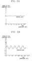
- a wobble signal is not generated at neither a groove track nor a land track in a first channel (CH1) corresponding to the sum of two signals output from the photo detector.
- a wobble signal is generated in a second channel (CH2) corresponding to the difference between two signals of the photo detector.
- the wobble signal is generated at the groove track and the land track only in the second channel CH2 corresponding to the difference between signals at opposite sides in view of a line parallel to the track.
- the wobble signal detected from the land track hereinafter, to be referred to simply as a land wobble signal
- the wobble signal detected from the groove track hereinafter, to be referred to simply as a groove wobble signal
- Figure 3 shows an exemplary recording medium according to a preferred embodiment of the present invention having wobbled groove tracks which are out of phase with wobbled land tracks.
- a disk usable in the present invention employs a polycarbonate substrate having a diameter of 120 mm, a thickness of 0.6 mm and a track pitch 0.34 ⁇ m.
- a light source used herein has a wavelength of 410 nm, and the read power is 0.5 mW.
- a wobble pattern formed on a groove track and a wobble pattern formed on a land track have a phase difference of ⁇ , and PIDs containing track and section numbers are positioned in the center of the track.
- the first half of the head fields are shifted from the latter half of the header fields by a track pitch.
- the PID may be recorded after it is shifted from the center of a land track or a groove track by half a track pitch, as shown in Figure 1.
- a groove wobble signal which is out of phase with a land wobble signal, and the land wobble signal are output to a first channel CH1 corresponding to the sum of two signals output from a photo detector, as shown in Figure 4A.
- the waveform of the groove wobble signal is indicated by a thin line and the waveform of the land wobble signal is indicated by a thick line, which may be reversed.
- a wobble signal is output at neither the groove track nor the land track in the second channel CH2 corresponding to the difference between two signals output from the photo detector, i.e., the signals cancel each other out.
- all signals can be processed using the signals output to the first channel CH1, including user data, wobble signals and PIDs. Also, the position information of a groove track or a land track can be detected by the difference in phase with the wobble signals output to the first channel CH1.
- Figure 5 illustrates a recording medium having wobbled groove tracks which are out of phase with wobbled land tracks according to another embodiment of the present invention, in which the wobbles of individual groove tracks are out of phase by ⁇ and the wobbles of individual land tracks are in phase. Also, the phases of wobble signals even in an identical groove track are alternately opposite in a radial direction, and the phases of wobble signals even in an identical land track are alternately opposite in a radial direction. In other words, the differences in the wobble phases between a groove track and the very next groove track and between a land track and the very next land track are ⁇ .
- the wobbles of individual land tracks may be out of phase by ⁇ and the wobbles of individual groove track may be in phase.
- the differences in the wobble phases between a groove track and the directly next groove track and between a land track and the very next land track are ⁇ .
- a PID area containing track and section numbers may coincide with the center of a track. Otherwise, as shown in Figure 1, the PID area may be shifted from the center of a land track or a groove track by half a track pitch. If the PID area coincides with the center of a track, beam refraction is not necessary during mastering, nor is it necessary to use two beams. Even if two beams are used, the beam intensity only has only to be controlled, but position control does not necessarily have to be controlled.
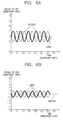
- a groove wobble signal is output to a first channel CH1 corresponding to the sum of two signals output from a photo detector, as shown in Figure 6A. Also, as shown in Figure 6B, a land wobble signal is output to the second channel CH2 corresponding to the difference between two signals output from the photo detector.
- a land wobble signal is output to the first channel CH1 and a groove wobble signal is output to the second channel CH2.
- a track currently being picked up is either a groove track or a land track, using the wobble signals of the first and second channels CH1 and CH2. Also, it is possible to control movement of a pickup to a desired physical area in a stable manner using both the wobble signals output to the first and second channels CH1 and CH2 and the PID generated in the center of the track. Further, in not only a rewritable disk but also a read-only disk, when the position of the pickup is switched from the land track to a groove track, or when the position of the pickup is switched from the groove track to a land track, the wobble signals output from the first and second channels CH1 and CH2 can be effectively used for servo control.
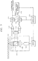
- Figure 7 is a block diagram of a servo controlling apparatus for controlling a pickup suitable for use with the recording medium shown in Figure 5.
- the servo controlling apparatus includes a recording medium 102, a pickup unit 104, a photo detector 118, first and second differential amplifiers 120 and 122, first and second sample-and-hold (S/H) circuits 124 and 126, a wobble signal determiner 128, a controller 130 and a servo unit 132.
- the first and second differential amplifiers 120 and 122, and the first and second S/H circuits 124 and 126 can be collectively referred to as a wobble signal detector.
- a linearly polarized beam having an electrical field polarization plane parallel to the surface of land is emitted from a semiconductor laser 106.
- the beam spread elliptically is collimated by a collimator 108, which is also called a coupling lens.
- the linearly polarized laser beam having a polarization plane parallel to the surface of land passes through a beam splitter 110 and an optical isolator which consists of a 1/4 wavelength plate 112 to then be a circular, polarized beam.
- the circular, polarized beam is reflected from a disk so that it passes through again the 1/4 wavelength plate 112 to then become a linearly polarized beam having a polarization plane perpendicular to the surface of land.
- the linearly polarized beam is reflected from the beam splitter 110 to be directed toward a focusing lens, which is also called a detecting lens 116.
- the beam incident into the disk 102 is a polarized beam, but a nonpolarized beam may be incident into the disk 102.
- the photo detector 118 divides a light signal emitted through the focusing lens 116 and supplies the two divided signals to the first and second differential amplifiers 120 and 122.
- the first differential amplifier 120 supplies the sum of the two signals of the photo detector 118 to the first S/H circuit 124 through a first channel CH1
- the second differential amplifier 122 supplies the difference between the two signals of the photo detector 118 to the second S/H circuit 126 through a second channel CH2.
- the groove (or land) wobble signal detected from the first channel CH1, output from the first S/H circuit 124 is supplied to the wobble signal determiner 128 and the controller 130.
- the PID detected from the first channel CH1 through the first S/H circuit 124 is supplied to the controller 130, and a reproduction signal is supplied to a reproduction signal processor (not shown).
- the land (or groove) wobble signal detected from the second channel CH2, output from the second S/H circuit 126 is supplied to the wobble signal determiner 128 and the controller 130.
- the controller 130 controls the timing of the first and second S/H circuits 124 and 126.
- the wobble signal determiner 128 determines that the wobble signal is in a groove (or land) track. If a wobble signal is detected from the second channel CH2, the wobble signal determiner 128 determines that the wobble signal is in a land (or groove) track.
- the controller 130 generates a control signal for controlling the servo unit 132 so that the pickup unit is moved to a desired physical area in a stable manner in accordance with a determination signal supplied from the wobble signal determiner 128, the groove (or land) wobble signal and the PID detected from the first channel CH1 through the first S/H circuit 124, and the land (or groove) wobble signal detected from the second channel CH2 through the second S/H circuit 126.
- the control signal may be a signal for controlling the revolution speed of a spindle motor or a signal for controlling a tracking servo.
- a wobble signal is output to the first channel CH1. If a pickup unit is currently tracking a land (or groove) track, a wobble signal is output to the second channel CH2. Also, since the phases of wobbles of individual groove tracks and individual land tracks are alternated, it is possible to discriminate whether the groove or land track number is an odd number or an even number, thereby ensuring addressing.
- the wobble signals of both first and second channels are used as switching signals between a groove track and a land track.
- PIDs having desired information can be recorded on a precise position by using only a track number and a sector number during mastering.
- a groove track or a land track is determined from a recording medium having wobbled groove tracks which are out of phase with wobbled land tracks using wobble signals of two channels. Also, it is possible to determine whether a groove (or land) track number is an odd number or an even number. Thus, addressing is ensured and servo control can be effectively performed.
Landscapes
- Optical Recording Or Reproduction (AREA)
- Optical Record Carriers And Manufacture Thereof (AREA)
Abstract
Description
Claims (24)
- A recording medium (102) having land tracks and groove tracks, wherein both the land tracks and the groove tracks are wobbled, and wherein the wobbles of either individual groove tracks or individual land tracks are out of phase and the wobbles of the other individual tracks are in phase.
- The recording medium according to claim 1, wherein the wobbles formed on a groove track have a phase difference of Π with respect to the wobbles of an adjacent groove track in a radial direction, and the wobbles formed on a land track have a phase difference of Π with respect to the wobbles of an adjacent land track in a radial direction.
- The recording medium according to claim 1, wherein the wobbles of individual groove tracks are out of phase and the wobbles of individual land tracks are in phase.
- The recording medium according to claim 1, wherein the wobbles of individual groove tracks have a phase difference of Π.
- The recording medium according to claim 3, wherein the wobbles of individual land tracks are out of phase and the wobbles of individual groove tracks are in phase.
- The recording medium according to claim 5, wherein the wobbles of individual land tracks have a phase difference of Π.
- The recording medium according to any of claims 1 to 6, wherein a physical identifier header for storing a track number and a sector number is prepitted in the center of a track.
- The recording medium according to any of claims 1 to 6, wherein a physical identifier header for storing a track number and a sector number is shifted from the center of a track to then be prepitted.
- A recording medium (102) having land tracks and groove tracks, wherein both the land tracks and the groove tracks are wobbled, and wherein the wobbles of individual groove tracks and individual land tracks are out of phase.
- The recording medium according to claim 9, wherein the wobbles formed of individual land tracks and individual groove tracks have a phase difference of Π, respectively.
- The recording medium according to claim 9 or 10, wherein a physical identifier header for storing a track number and a sector number is prepitted in the center of a track.
- The recording medium according to claim 9 or 10, wherein a physical identifier header for storing a track number and a sector number is shifted from the center of a track to then be prepitted.
- A servo controlling apparatus for use in an optical recording and/or reproducing apparatus having a pickup unit for tracking an optical recording medium (102), the servo controlling apparatus comprising:a photo detector (118) for outputting as two channels a light signal reflected from the optical recording medium (102) wherein the wobbles of either individual groove tracks or individual land tracks are out of phase and the wobbles of the other tracks are in phase, or the wobbles of individual groove tracks and individual land tracks are out of phase, respectively;a wobble signal detector (120,122,124,126) for detecting a wobble signal from at least one channel from the two channels;a wobble signal determiner (128) for determining whether a track which is currently tracked by the pickup unit is a groove track or a land track, and to provide a determination signal; anda controller (130) for generating a control signal for controlling a servo for moving the pickup unit using the determination signal and the detected wobble signal.
- The servo controller according to claim 13, wherein if the wobbles of individual land tracks and individual groove tracks are out of phase, the wobble signal detector (120-126) detects a groove wobble signal and a land wobble signal from a first channel corresponding to the sum of two signals output from the photo detector, the detected groove wobble signal and the land wobble signal being out of phase with respect to each other.
- The servo controller according to claim 13, wherein if the wobbles of individual groove tracks have a phase difference of Π, the wobbles of individual land tracks are in phase, the wobbles formed on a groove track have a phase difference of Π with respect to the wobbles of an adjacent groove track in a radial direction, and if the wobbles formed on a land track have a phase difference of Π with respect to the wobbles of an adjacent land track in a radial direction, the wobble signal detector (120-126) detects a groove wobble signal from a first channel corresponding to the difference between two signals output from the photo detector (118) and the wobble signal detector (120-126) detects a land wobble signal from a second channel corresponding to the sum of two signals output from the photo detector (118).
- The servo controller according to claim 15, wherein the controller (130) detects the positions of the land tracks and the groove tracks and detects whether the groove/land track number is an odd number or an even number, according to the determination signal and the groove and land wobble signals.
- The servo controller according to claim 13, wherein if the wobbles of individual land tracks have a phase difference of Π, the wobbles of individual groove tracks are in phase, the wobbles formed on a groove track have a phase difference of Π with respect to the wobbles of an adjacent groove track in a radial direction, and if the wobbles formed on a land track have a phase difference of Π with respect to the wobbles of an adjacent land track in a radial direction, the wobble signal detector (120-126) detects a land wobble signal from a first channel corresponding to the difference between two signals output from the photo detector (118) and the wobble signal detector (120-126) detects a groove wobble signal from a second channel corresponding to the sum of two signals output from the photo detector (118).
- The servo controller according to claim 17, wherein the controller detects the positions of the land tracks and the groove tracks and detects whether the groove/land track number is an odd number or an even number, according to the determination signal and the groove and land wobble signals.
- A servo controlling method for use in an optical recording and/or reproducing apparatus having a pickup unit (104) for tracking an optical recording medium (102), comprising the steps of:(a) outputting as two channels a light signal reflected from the optical recording medium (102) wherein the wobbles of either individual groove tracks or individual land tracks are out of phase and the wobbles of the other individual tracks are in phase, or the wobbles of individual groove tracks and individual land tracks are out of phase, respectively;(b) detecting a wobble signal from at least one channel from the two channels;(c) determining whether a track which is currently tracked by the pickup unit is a groove track or a land track to provide a determination signal; and(d) controlling a servo for moving the pickup unit using the determination signal and the detected wobble signal.
- The method according to claim 19, wherein if the wobbles of individual land tracks and individual groove tracks are out of phase, in the step (b), a groove wobble signal and a land wobble signal are detected from a first channel corresponding to the sum of two signals output from the photo detector, the detected groove wobble signal and the land wobble signal being out of phase.
- The method according to claim 19, wherein if the wobbles of individual groove tracks have a phase difference of Π, the wobbles of individual land tracks are in phase, the wobbles formed on a groove track have a phase difference of Π with respect to the wobbles of an adjacent groove track in a radial direction, and if the wobbles formed on a land track have a phase difference of Π with respect to the wobbles of an adjacent land track in a radial direction, in the step (b), a groove wobble signal is detected from a first channel corresponding to the difference between two signals output in the step (a) and a land wobble signal is detected from a second channel corresponding to the sum of two signals output in the step (a).
- The method according to claim 21, further comprising the step (e) of detecting the positions of the land tracks and the groove tracks and detecting whether the groove/land track number is an odd number or an even number according to the determination signal and the groove and land wobble signals.
- The method according to claim 19, wherein if the wobbles of individual land tracks have a phase difference of Π, the wobbles of individual groove tracks are in phase, the wobbles formed on a land track have a phase difference of Π with respect to the wobbles of an adjacent land track in a radial direction, and if the wobbles formed on a groove track have a phase difference of Π with respect to the wobbles of an adjacent groove track in a radial direction, in the step (b), a land wobble signal is detected from a first channel corresponding to the difference between two signals output from the step (a) and a groove wobble signal is detected from a second channel corresponding to the sum of two signals output from the step (a).
- The method according to claim 23, further comprising the step (e) of detecting the positions of the land tracks and the groove tracks and detecting whether the groove/land track number is an odd number or an even number according to the determination signal and the groove and land wobble signals.
Applications Claiming Priority (2)
| Application Number | Priority Date | Filing Date | Title |
|---|---|---|---|
| KR1019990003956A KR100565044B1 (en) | 1999-02-05 | 1999-02-05 | Recording medium having wobbled groove tracks out of phase with wobbled land track, servo control device using wobble signal and method thereof |
| KR9903956 | 1999-02-05 |
Publications (3)
| Publication Number | Publication Date |
|---|---|
| EP1026672A2 true EP1026672A2 (en) | 2000-08-09 |
| EP1026672A3 EP1026672A3 (en) | 2001-01-24 |
| EP1026672B1 EP1026672B1 (en) | 2004-07-07 |
Family
ID=19573505
Family Applications (1)
| Application Number | Title | Priority Date | Filing Date |
|---|---|---|---|
| EP00300844A Expired - Lifetime EP1026672B1 (en) | 1999-02-05 | 2000-02-03 | Recording medium having wobbled groove tracks out of phase with wobbled land tracks, servo controlling apparatus using wobble signal and method thereof |
Country Status (5)
| Country | Link |
|---|---|
| EP (1) | EP1026672B1 (en) |
| JP (1) | JP3249104B2 (en) |
| KR (1) | KR100565044B1 (en) |
| CN (1) | CN1193354C (en) |
| DE (1) | DE60011947T2 (en) |
Cited By (3)
| Publication number | Priority date | Publication date | Assignee | Title |
|---|---|---|---|---|
| RU2262141C2 (en) * | 2001-08-02 | 2005-10-10 | Мацусита Электрик Индастриал Ко., Лтд. | Optical disk and physical address format |
| EP1098302A3 (en) * | 1999-11-03 | 2007-12-12 | SAMSUNG ELECTRONICS Co. Ltd. | Physical identification data addressing method using wobble signal, wobble address encoding circuit, method and circuit for detecting wobble address, and recording medium |
| US7944784B2 (en) | 2005-03-11 | 2011-05-17 | Mediatek Inc. | Land/groove track and pickup head movement direction detection |
Families Citing this family (5)
| Publication number | Priority date | Publication date | Assignee | Title |
|---|---|---|---|---|
| KR100698105B1 (en) * | 1999-12-30 | 2007-03-26 | 엘지전자 주식회사 | Method and apparatus for determining land / groove track of optical record carrier |
| DE60233511D1 (en) | 2001-07-18 | 2009-10-08 | Sony Corp | SUBSTRATE FOR USE OF OPTICAL RECORDING / REPRODUCING MEDIUM, MANUFACTURING PROCESS FOR OPTICAL RECORDING / REPRODUCTION MEDIUM, PRODUCTION STAMP AND PRODUCTION STAMP FOR OPTICAL RECORDING / REPRODUCING MEDIUM |
| JP3736398B2 (en) * | 2001-08-01 | 2006-01-18 | ティアック株式会社 | Optical disk device |
| KR100432847B1 (en) * | 2001-10-29 | 2004-05-24 | 주식회사 히타치엘지 데이터 스토리지 코리아 | An apparatus and method for detecting wobble signal |
| CN1331119C (en) * | 2004-03-09 | 2007-08-08 | 蒂雅克股份有限公司 | Optical disk device and optical disk |
Family Cites Families (9)
| Publication number | Priority date | Publication date | Assignee | Title |
|---|---|---|---|---|
| JP3051526B2 (en) * | 1991-11-08 | 2000-06-12 | パイオニア株式会社 | Servo device for optical head in optical recording / reproducing device |
| JP2860229B2 (en) * | 1993-06-25 | 1999-02-24 | 株式会社ケンウッド | Optical disk recording and playback device |
| JPH07161045A (en) * | 1993-12-03 | 1995-06-23 | Sharp Corp | Optical disc and optical recording / reproducing apparatus |
| KR980011178A (en) * | 1996-07-13 | 1998-04-30 | 구자홍 | Addressable wobbled optical disc |
| EP0930611A4 (en) | 1996-09-26 | 2003-02-12 | Sanyo Electric Co | Recording medium and its reproducer |
| WO1998016929A1 (en) * | 1996-10-11 | 1998-04-23 | Sanyo Electric Co., Ltd. | Digital recording method, digital disk, digital disk recording device, and digital disk reproducing device |
| JPH117660A (en) * | 1996-10-22 | 1999-01-12 | Hitachi Ltd | Information recording medium and information recording / reproducing apparatus for representing information by swinging track |
| US6069870A (en) * | 1996-10-22 | 2000-05-30 | Hitachi, Ltd. | Information recording medium which indicates information according to the wobbling of a track and information recording and reproducing apparatus |
| JPH1116175A (en) * | 1997-06-23 | 1999-01-22 | Sony Corp | Optical disk drive |
-
1999
- 1999-02-05 KR KR1019990003956A patent/KR100565044B1/en not_active Expired - Fee Related
-
2000
- 2000-02-03 DE DE60011947T patent/DE60011947T2/en not_active Expired - Lifetime
- 2000-02-03 EP EP00300844A patent/EP1026672B1/en not_active Expired - Lifetime
- 2000-02-04 JP JP2000028351A patent/JP3249104B2/en not_active Expired - Fee Related
- 2000-02-05 CN CNB001045180A patent/CN1193354C/en not_active Expired - Fee Related
Cited By (3)
| Publication number | Priority date | Publication date | Assignee | Title |
|---|---|---|---|---|
| EP1098302A3 (en) * | 1999-11-03 | 2007-12-12 | SAMSUNG ELECTRONICS Co. Ltd. | Physical identification data addressing method using wobble signal, wobble address encoding circuit, method and circuit for detecting wobble address, and recording medium |
| RU2262141C2 (en) * | 2001-08-02 | 2005-10-10 | Мацусита Электрик Индастриал Ко., Лтд. | Optical disk and physical address format |
| US7944784B2 (en) | 2005-03-11 | 2011-05-17 | Mediatek Inc. | Land/groove track and pickup head movement direction detection |
Also Published As
| Publication number | Publication date |
|---|---|
| JP2000231730A (en) | 2000-08-22 |
| EP1026672A3 (en) | 2001-01-24 |
| KR100565044B1 (en) | 2006-03-30 |
| DE60011947T2 (en) | 2005-07-28 |
| EP1026672B1 (en) | 2004-07-07 |
| CN1193354C (en) | 2005-03-16 |
| KR20000055373A (en) | 2000-09-05 |
| CN1264111A (en) | 2000-08-23 |
| JP3249104B2 (en) | 2002-01-21 |
| DE60011947D1 (en) | 2004-08-12 |
Similar Documents
| Publication | Publication Date | Title |
|---|---|---|
| KR100324848B1 (en) | Optical reproducting device | |
| JP4231759B2 (en) | Optical information recording device | |
| KR100819625B1 (en) | Optical pickup apparatus, optical disc apparatus, and track recognition signal detection method | |
| KR19990037067A (en) | Magneto-optical information recording and reproducing apparatus and method | |
| US6847594B1 (en) | Recording medium having wobbled groove tracks out of phase with wobbled land tracks, servo controlling apparatus using wobble signal and method thereof | |
| US6667947B2 (en) | Optical multi-layer information recordating medium | |
| EP1026672B1 (en) | Recording medium having wobbled groove tracks out of phase with wobbled land tracks, servo controlling apparatus using wobble signal and method thereof | |
| US5999502A (en) | Optical information recording/reproducing apparatus having focus servo control compensation for lands and grooves | |
| EP0737964A1 (en) | An apparatus for and method of reproducing information from different types of optical disks and an optical disk recording/reproducing apparatus | |
| US7239603B1 (en) | Recording medium with judging area for track area identification based on wobbling polarity | |
| US5732051A (en) | Focusing control apparatus using dynamic target value in relation to land/groove | |
| JP2001134961A (en) | Optical recording/reproducing device | |
| JP3064860B2 (en) | Focus control device and recording medium | |
| US6147952A (en) | Optical disk apparatus for reproducing information from an optical recording medium | |
| KR19990077952A (en) | Optical disk device | |
| KR100682024B1 (en) | Optical pickup device, optical disc device and track discrimination signal detection method | |
| US6373808B1 (en) | Optical pick-up apparatus capable of eliminating a cross-talk component from adjacent tracks | |
| KR20040085033A (en) | Optical pickup and disc apparatus | |
| KR100681613B1 (en) | Track servo control method using reference light servo of holographic ROM and its device | |
| JP3833038B2 (en) | Magneto-optical recording / reproducing apparatus | |
| US7965609B2 (en) | Optical pickup device and optical recording medium information reproduction device | |
| JP2924880B2 (en) | Optical disc recording / reproducing apparatus and recording / reproducing method | |
| KR20060067588A (en) | Method for controlling reference light servo of holographic ROM disk and device therefor | |
| KR20020074996A (en) | Interchangeable high density optical disc and optical disc apparatus | |
| JPH09212868A (en) | Discriminating device and reproducing device for optical recording medium |
Legal Events
| Date | Code | Title | Description |
|---|---|---|---|
| PUAI | Public reference made under article 153(3) epc to a published international application that has entered the european phase |
Free format text: ORIGINAL CODE: 0009012 |
|
| 17P | Request for examination filed |
Effective date: 20000229 |
|
| AK | Designated contracting states |
Kind code of ref document: A2 Designated state(s): DE FR GB NL |
|
| AX | Request for extension of the european patent |
Free format text: AL;LT;LV;MK;RO;SI |
|
| PUAL | Search report despatched |
Free format text: ORIGINAL CODE: 0009013 |
|
| AK | Designated contracting states |
Kind code of ref document: A3 Designated state(s): AT BE CH CY DE DK ES FI FR GB GR IE IT LI LU MC NL PT SE |
|
| AX | Request for extension of the european patent |
Free format text: AL;LT;LV;MK;RO;SI |
|
| AKX | Designation fees paid |
Free format text: DE FR GB NL |
|
| 17Q | First examination report despatched |
Effective date: 20021212 |
|
| GRAP | Despatch of communication of intention to grant a patent |
Free format text: ORIGINAL CODE: EPIDOSNIGR1 |
|
| GRAS | Grant fee paid |
Free format text: ORIGINAL CODE: EPIDOSNIGR3 |
|
| GRAA | (expected) grant |
Free format text: ORIGINAL CODE: 0009210 |
|
| AK | Designated contracting states |
Kind code of ref document: B1 Designated state(s): DE FR GB NL |
|
| REG | Reference to a national code |
Ref country code: GB Ref legal event code: FG4D |
|
| REF | Corresponds to: |
Ref document number: 60011947 Country of ref document: DE Date of ref document: 20040812 Kind code of ref document: P |
|
| ET | Fr: translation filed | ||
| PLBE | No opposition filed within time limit |
Free format text: ORIGINAL CODE: 0009261 |
|
| STAA | Information on the status of an ep patent application or granted ep patent |
Free format text: STATUS: NO OPPOSITION FILED WITHIN TIME LIMIT |
|
| 26N | No opposition filed |
Effective date: 20050408 |
|
| REG | Reference to a national code |
Ref country code: FR Ref legal event code: PLFP Year of fee payment: 16 |
|
| PGFP | Annual fee paid to national office [announced via postgrant information from national office to epo] |
Ref country code: NL Payment date: 20150223 Year of fee payment: 16 |
|
| PGFP | Annual fee paid to national office [announced via postgrant information from national office to epo] |
Ref country code: DE Payment date: 20150126 Year of fee payment: 16 |
|
| PGFP | Annual fee paid to national office [announced via postgrant information from national office to epo] |
Ref country code: FR Payment date: 20150127 Year of fee payment: 16 Ref country code: GB Payment date: 20150122 Year of fee payment: 16 |
|
| REG | Reference to a national code |
Ref country code: DE Ref legal event code: R119 Ref document number: 60011947 Country of ref document: DE |
|
| GBPC | Gb: european patent ceased through non-payment of renewal fee |
Effective date: 20160203 |
|
| REG | Reference to a national code |
Ref country code: NL Ref legal event code: MM Effective date: 20160301 |
|
| REG | Reference to a national code |
Ref country code: FR Ref legal event code: ST Effective date: 20161028 |
|
| PG25 | Lapsed in a contracting state [announced via postgrant information from national office to epo] |
Ref country code: FR Free format text: LAPSE BECAUSE OF NON-PAYMENT OF DUE FEES Effective date: 20160229 Ref country code: DE Free format text: LAPSE BECAUSE OF NON-PAYMENT OF DUE FEES Effective date: 20160901 Ref country code: GB Free format text: LAPSE BECAUSE OF NON-PAYMENT OF DUE FEES Effective date: 20160203 Ref country code: NL Free format text: LAPSE BECAUSE OF NON-PAYMENT OF DUE FEES Effective date: 20160301 |