EP1026371A1 - Lubricating oil feed passage structure in crank shaft - Google Patents
Lubricating oil feed passage structure in crank shaft Download PDFInfo
- Publication number
- EP1026371A1 EP1026371A1 EP00100661A EP00100661A EP1026371A1 EP 1026371 A1 EP1026371 A1 EP 1026371A1 EP 00100661 A EP00100661 A EP 00100661A EP 00100661 A EP00100661 A EP 00100661A EP 1026371 A1 EP1026371 A1 EP 1026371A1
- Authority
- EP
- European Patent Office
- Prior art keywords
- lubricating oil
- crank
- crank shaft
- passage
- shaft
- Prior art date
- Legal status (The legal status is an assumption and is not a legal conclusion. Google has not performed a legal analysis and makes no representation as to the accuracy of the status listed.)
- Granted
Links
- 239000010687 lubricating oil Substances 0.000 title claims abstract description 138
- 238000003754 machining Methods 0.000 abstract description 9
- 230000002093 peripheral effect Effects 0.000 description 17
- 239000003921 oil Substances 0.000 description 16
- 238000002485 combustion reaction Methods 0.000 description 5
- 230000033001 locomotion Effects 0.000 description 5
- 238000005553 drilling Methods 0.000 description 4
- 230000000694 effects Effects 0.000 description 2
- 230000005540 biological transmission Effects 0.000 description 1
- 239000000498 cooling water Substances 0.000 description 1
- 230000010485 coping Effects 0.000 description 1
- 230000003292 diminished effect Effects 0.000 description 1
- 238000009499 grossing Methods 0.000 description 1
- 230000001050 lubricating effect Effects 0.000 description 1
- 238000005461 lubrication Methods 0.000 description 1
- 238000000034 method Methods 0.000 description 1
- 238000000465 moulding Methods 0.000 description 1
- 238000007789 sealing Methods 0.000 description 1
Images

Classifications
-
- F—MECHANICAL ENGINEERING; LIGHTING; HEATING; WEAPONS; BLASTING
- F01—MACHINES OR ENGINES IN GENERAL; ENGINE PLANTS IN GENERAL; STEAM ENGINES
- F01M—LUBRICATING OF MACHINES OR ENGINES IN GENERAL; LUBRICATING INTERNAL COMBUSTION ENGINES; CRANKCASE VENTILATING
- F01M1/00—Pressure lubrication
- F01M1/06—Lubricating systems characterised by the provision therein of crankshafts or connecting rods with lubricant passageways, e.g. bores
Definitions
- the present invention relates to a lubricating oil feed passage structure formed in a crank shaft of an internal combustion engine to feed a lubricating oil to a connection surface for connection with a connecting rod connected to a crank pin.
- a driving sprocket d on which is entrained a cam chain for driving a cam shaft which is for driving intake and exhaust valves.
- a primary driving gear e and an oil pump or cooling water pump driving gear f are splined to an end portion of a crank shaft a, which extends from a crank journal b toward a crank case cover c. They are tightened and fixed with a nut g through a washer.
- a lubricating oil passage comprising a passage i extending coaxially with the crank shaft a, a passage m extending from the passage i, and reaching a hollow portion k of a crank pin j and a passage p which extends from the hollow portion k and is open to a connecting rod connection surface of the crank pin j with a large end portion n of the connecting rod being connected to the connection surface through a bearing.
- a tip end of the crank shaft end portion gets into a lubricating oil chamber r formed in the crank case cover c.
- An oil seal s which is fixed to an open end of the lubricating oil chamber r, comes into sliding contact with an outer periphery of the tip end of the crank shaft end portion to prevent the lubricating oil present in the lubricating oil chamber from leaking through the tip end outer periphery.
- the lubricating oil fed from an oil pump into the lubricating oil chamber r through a filter then flows through an opening formed in the end face of the crank shaft end portion, further through the lubricating oil passages i, m, k, p and is fed between the connecting rod connection surface of the crank pin j, and the bearing for the large connecting rod end portion n to lubricate the sliding portion.
- the passage, i, formed toward the crank arm, h, from the end face of the crank shaft end portion and extending coaxially with the crank shaft, a is a long passage, because it passes through a relatively long shaft end portion where there are formed the mounting portion for the driving sprocket d, primary driving gear e, and auxiliary device driving gear f, the mounting portion for the nut g, and the tip end portion extending up to the lubricating oil chamber, r, formed in the crank case cover, c. It has not been easy to machine a bore for forming such a long passage.
- the invention defined in claim 3 intends, in addition to what is to be attained by the invention of claim 2, to be capable of easily coping with a case where the spacing between the end face of the crank shaft end portion and the lubricating oil chamber differs depending on the model of a vehicle.
- the invention defined in claim 1 relates to a lubricating oil feed passage structure in a crank shaft, comprising: a lubricating oil passage formed in the crank shaft which has a crank pin with a connecting rod connected thereto, the lubricating oil passage having an inlet end and an outlet end which is open to a connection surface for connection with the connecting rod of the crank pin; a lubricating oil introducing member mounted at an end portion of the crank shaft so as to project in an axial direction of the crank shaft from an end face of the crank shaft end portion; and a lubricating oil introducing passage formed axially through the lubricating oil introducing member and connected to the inlet end.
- the length of the crank shaft end portion becomes smaller than in the prior art by an amount corresponding to the length of the lubricating oil introducing member projecting from the end face of the crank shaft end portion, so that the length of the lubricating oil passage formed in the shaft end portion becomes smaller and hence the machining for the lubricating oil passage to be formed in the crank shaft becomes easier.
- the lubricating oil introducing member is a bolt which prevents the torque member from moving in the axial direction of the crank shaft, and thus the bolt is utilized also as a lubricating oil introducing member, so the length of the crank shaft end portion can be made smaller by an amount corresponding to the length of the bolt projecting from the end face of the crank shaft end portion.
- the projecting bolt length is also included the length of the nut mounting portion in the prior art.
- the head of the aforesaid bolt has a cylindrical portion, which portion is positioned within the lubricating oil chamber formed in the crank case cover.
- a lubricating oil feed passage structure in a crank shaft according to the first embodiment of the present invention is applied to a crank shaft 1 of an overhead camshaft type V-shaped 2-cyliner internal combustion engine mounted on such a vehicle as a motorcycle.
- the crank shaft 1 is supported by a crank case 3 which is divided into upper and lower halves through two right and left bearings 2 (only the right-hand one is shown) serving as main bearings.
- Passages 4 for feeding a lubricating oil to the bearings 2 are formed respectively in support portions for the bearings 2 of the crank case 3.
- the crankshaft 1 comprises crankpins 1a, crank journals 1b. crank arms 1c, and balance weights 1d, which are formed integrally by molding.
- Large end portions 5a of connecting rods 5, whose small end portions are pivotally secured to piston pins mounted to pistons of the cylinders, are respectively connected to the crank pins 1a in an adjacent manner. More specifically, the large end portions 5a of the connecting rods are slidably fitted on outer peripheries of the crank pins 1a serving as connection surfaces for connection with the connecting rods 5, through bearings 6 fixed to inner peripheries of the crank pins 1a. A lubricating oil is fed between the connecting rods 5 and the connection surfaces of the crank pins 1a to diminish a frictional resistance induced between the two.
- a reciprocating motion of each piston transferred through the associated connecting rod 5 is converted to a rotational motion and the resulting torque of the crank shaft 1 is transmitted to a rear wheel via a multiple-disc friction clutch 7, a constant mesh type gear transmission 8 and a driving chain.
- the transfer of the torque between the crank shaft 1 and the multiple-disc friction clutch 7 is performed by a primary reduction mechanism comprising a primary driving gear 9 splined to an end portion 1e of the crank shaft 1 and a primary driven gear 11 connected to a clutch housing of the multiple-disc friction clutch 7 through a damper.
- the primary driving gear 9 has a primary sub gear 9a connected thereto through an elastic member which is a spring for the purpose of eliminating backlash between it and the primary driven gear 11.
- the primary sub gear 9a is fitted on an outer periphery of a boss portion 9b formed on a thrust washer 31 side to be described later of the primary driving gear 9.
- An end face of the primary sub gear 9a and that of the boss portion 9b are cable of coming into abutment against the thrust washer 31.
- the end portion 1e of the crank shaft 1 is constituted of a portion of the crank shaft 1 which portion extends from the right-hand crank journal 1b toward a right-hand crank case cover 12.
- An outer periphery of the shaft end portion 1e has an outer peripheral portion 1f and a spline portion 1g, the outer peripheral portion if being positioned near a crank journal 1b and having a smooth circumferential surface.
- the spline portion 1g is formed as a small-diameter portion which extends from the outer peripheral portion 1f toward an end face 1h of the shaft end portion 1e and which has an outside diameter smaller than that of the outer peripheral portion 1f.
- the spline portion 1g comprises a plurality of spline grooves and spline ridges formed in parallel with a crank shaft axis L1.
- the outside diameter of the outer peripheral portion 1f is set larger than that of the spline ridges of the spline portion 1g.
- both gears 9 and 10 are connected to the crank shaft 1 so as to be unmovable in the rotating direction of the crank shaft and rotatable integrally with the crank shaft.
- an inner peripheral portion 10a On the inner periphery of the timing gear 10 and at a position close to the right-hand crank journal 1b is formed an inner peripheral portion 10a having a smooth circumferential surface to be fitted with the outer peripheral portion 1f which is formed at the shaft end portion 1e. Since the outer peripheral portion 1f and the inner peripheral portion 10a are fitted together by clearance fit, there is performed an accurate centering of the timing gear 10 with respect to the crank shaft 1. Further, a more accurate centering can be effected by subjecting the outer and inner peripheral portions 1f, 10a to an abrasive machining. By this centering operation, vibration of the timing gear relative to the crank shaft 1 is prevented and hence the generation of noise based on the vibration is suppressed.
- the work for fitting the outer peripheral portion 1f and the inner peripheral portion 10a is easy because of clearance fit. Further, since the outside diameter of the outer peripheral portion 1f is larger than that of the spline portion 1g of the crank shaft 1, the fitting of the outer and inner peripheral portions 1f, 10a can be done without being influenced by splining at the spline portion 1g, thus permitting a more accurate centering work.
- the rotation of the timing gear 10 is transmitted through a series of gears to a cam shaft installed in the cylinder head and intake and exhaust valves are driven in accordance with rotation of the cam shaft.
- the small-diameter portion of the stepped hole 21 is located at a position close to the crank arm 1c (close to the bottom), while the large-diameter portion of the hole 21 is positioned close to the end face 1h of the shaft end portion 1e (close to the open end).
- the peripheral wall of the large-diameter portion is internally threaded at a portion thereof close to the open end and the crank center bolt 30, which will be described later, comes into engagement with the internal threads.
- the stepped hole 21 thus formed constitutes a first lubricating oil passage 21 for feeding the lubricating oil to the foregoing connection surface of the crank pin 1a.
- crank pin 1a In the crank pin 1a is formed a bottomed hole 23 by drilling from the right-hand side of the crank arm 1c, the bottomed hole 23 extending from the right-hand side of the right-hand crank arm 1c toward the crank pin 1a and having an axis parallel to a crank pin axis L2.
- the axis of the hole 23 lies on a plane including both crank pin axis L2 and crank shaft axis L1 and is positioned on the side opposite to the crank shaft axis L1 with respect to the crank pin axis L2.
- the diameter of the hole 23 is set larger than the diameter of the small-diameter portion of the stepped hole 21 and thus the hole 23 functions to store the lubricating oil which has entered the hole.
- the lubricating oil can be fed stably to the foregoing connection surface of the crank pin 1a through a fourth lubricating oil passage 24 which will be described later.
- the hole 23 thus formed constitutes a third lubricating oil passage 23 for feeding the lubricating oil to the foregoing connection surface of the crank pin 1a.
- a passage portion of the third lubricating oil passage 23 positioned closer to the open end with respect to a cup-like member 25 is set larger in diameter than the other passage portion of the third lubricating oil passage 23 and in it circumferential wall is formed an annular groove in which a clip 26 is fitted by virtue of an elastic force thereof.
- the clip 26 prevents the cup-like member 25 from coming off the third lubricating oil passage 23.
- a hole 22 is formed by drilling from an outer peripheral portion of the crank arm 1c close to the crank pin 1a, the hole 22 extending from the outer peripheral portion toward the balance weight 1d through the third lubricating oil passage 23 and reaching an innermost portion of the first lubricating oil passage 21 (the bottom of the small-diameter portion of the stepped hole 21).
- the hole 22 has an axis perpendicular to the axes of the first and third lubricating oil passages 21, 23 and has the same diameter as the diameter of the small-diameter portion of the stepped hole 21.
- a portion of the hole 22 located closer to the open end with respect to the portion where the hole 22 crosses the third lubricating oil passage 23 is closed by a ball member 27 which is a sealing plug.
- the hole 22 thus formed constitutes a second lubricating oil passage 22 for feeding the lubricating oil to the foregoing connection surface of the crank pin 1a.
- each crank pin 1a by drilling from the connection surface side of each crank pin 1a there are formed two holes 24 which are open to the third lubricating oil passage 23 in the portion corresponding to the large end portion 5a of each connecting rod 5.
- the holes 24 constitutes a fourth lubricating oil passage 24 for feeding the lubricating oil to the connection surface. With the lubricating oil flowing out from the fourth lubricating oil passage 24 there is effected lubrication between the bearing 6 at the large end portion 5a of the connecting rod 5 and the connection surface.
- the above first to fourth lubricating oil passages 21, 22, 23, 24 constitute the lubricating oil passage formed in the crank shaft 1.
- the portion of the first lubricating oil passage 21 adjacent to an end face of a shaft portion 30a of the crank center bolt 30 corresponds to an inlet end of the lubricating oil passage formed in the crank shaft, while an open end of the fourth lubricating oil passage 24 located on the foregoing connection surface side corresponds to an outlet end of the lubricating oil passage formed in the crank shaft.
- crank center bolt 30 External threads formed on the shaft portion 30a of the crank center bolt 30 come into threaded engagement with the internal threads formed in the large-diameter portion of the stepped hole 21, whereby the crank center bolt 30 is secured to the end portion 1e of the crank shaft 1.
- the head of the crank center bolt 30 comprises a hexagonal prism portion adjacent to the shaft portion 30a and formed with a flange portion 30b and a cylindrical portion 30d extending axially from the hexagonal prism portion 30c.
- a lip portion of an oil seal 34 comes into sliding contact with the outer periphery of the cylindrical portion 30d as will be described later, so the outer periphery of the cylindrical portion 30d is subjected to abrasive machining for smoothing the sliding contact portion.
- crank center bolt 30 In the crank center bolt 30 is formed a through hole 30e from an end face of the cylindrical portion 30d of the bolt head toward the end face of the shaft portion 30a, the through hole 30e having an axis aligned with the axis of the crank center bolt 30 and hence aligned with the axis of the crank shaft axis L1.
- the trough hole 30e thus formed constitutes a lubricating oil introducing passage 30e which is connected to the inlet end of the lubricating oil passage formed in the crank shaft 1.
- crank center bolt 30 with a thrust washer 31 fitted thereon, is brought into threaded engagement with the internal threads of the stepped hole 21 by means of a tool which is applied to the hexagonal prism portion 30c.
- an end face of the timing gear 10 on the crank journal 1b side comes into abutment against an end face of the crank journal 1b
- an end face of the timing gear 10 on the primary driving gear 9 side and an end face of the primary driving gear 9 on the timing gear 10 side come into abutment against each other
- an end face of the primary driving gear 9 on the thrust washer 31 side and an end face of the boss portion 9b on the thrust washer 31 side come into abutment against the thrust washer 31, whereby the timing gear 10 and the primary driving gear 9 both mounted on the shaft end portion 1e are prevented from moving in the crank axis L1 direction, as noted previously.
- a slight gap 32 is formed between the end face 1h of the end portion 1e of the crank shaft 1 and the thrust washer 31.
- a first oil hole 30f which is open not only to the lubricating oil introducing passage 30e but also to the gap 32, is formed in the shaft portion 30a of the crank center bolt 30 in the vicinity of the portion where the thrust washer 31 is fitted thereon, the first oil hole 30f being formed perpendicularly to the axis of the lubricating oil introducing passage 30e, and also formed is a second oil hole 9d extending radially through the fitted portion of the boss portion 9b.
- a portion of the lubricating oil flowing through the lubricating oil introducing passage 30e passes through the first oil hole 30f and the gap 32, further passes through the second oil hole 9d and is fed to the fitted portion of the primary sub gear 9a and the boss portion 9b of the primary driving gear 9.
- the crank center bolt 30 not only functions as a fixing member for fixing the timing gear 10 and the primary driving gear 9 as torque transfer members but also functions as a lubricating oil introducing member for introducing the lubricating oil to the lubricating oil passage formed in the crank shaft.
- the length of the end portion 1e of the crank shaft 1 is smaller by a distance corresponding to the projecting length of the crank center bolt 30 from the end face 1h of the shaft end portion 1e. Consequently, the length of the first lubricating oil passage 21 formed in the crank shaft 1 also becomes shorter than in the prior art, thus facilitating machining for the same passage.
- a recess as a lubricating oil chamber 33.
- the lubricating oil chamber 33 is positioned on the crank shaft axis L1 and hence on the axis of the lubricating oil introducing passage 30e formed in the crank center bolt 30 and is open toward the crank shaft 1, which position of the lubricating oil chamber 33 permits the cylindrical portion 30d of the crank center bolt head to get into the same chamber.
- the oil seal 34 is fixed to an open end portion of the lubricating oil chamber 33 and the lip portion thereof is in sliding contact with the polished outer periphery of the cylindrical portion 30d positioned within the lubricating oil chamber 33 to keep liquid-tight between the open end portion of the lubricating oil chamber 33 and the cylindrical portion 30d, thus preventing the lubricating oil present in the lubricating oil chamber 33 from leaking through the outer periphery of the cylindrical portion 30d.
- the lubricating oil which is pressurized by the oil pump, passes through the filter and the passage formed in the right-hand crank case cover 12, then is fed into the lubricating oil chamber 33 formed in the cover 12 and is stored therein.
- the lubricating oil present in the lubricating oil chamber 33 flows through the lubricating oil introducing passage 30e formed in the crank center bolt 30, enters the first lubricating oil passage 21 formed in the crank shaft 1, further passes through the second, third and fourth lubricating oil passages 22, 23, 24, then is discharged to the connection surface of the crank pin 1a and is fed between the bearing 6 at the large end portion 5a of each connecting rod 5 as a sliding portion and the connection surface of the crank pin 1a.
- the lubricating oil is taken into the lubricating oil passage formed in the crank shaft 1 through the lubricating oil introducing passage 30e formed in the crank center bolt 30 which projects in the crank shaft axis L1 direction from the end face 1h of the end portion 1e of the crank shaft 1, the length of the end portion 1e of the crank shaft 1 becomes smaller than in the prior art by a distance corresponding to the projecting length of the crank center bolt 30 from the end face 1h of the end portion 1e of the crank shaft 1. Consequently, the lubricating oil passage formed in the shaft end portion 1e becomes shorter and so the machining for the lubricating oil passage to be formed in the crank shaft 1 becomes easier.
- the crank center bolt 30 Since the lubricating oil introducing passage 30e is formed in the crank center bolt 30 which prevents the timing gear 10 and the primary driving gear 9 from moving in the crank shaft axis L1 direction, the crank center bolt 30 as a single member not only functions as a fixing member for fixing the timing gear 10 and the primary driving gear 9 but also functions as a lubricating introducing member for introducing the lubricating oil into the lubricating oil passage, thus making it possible to reduce the number of components used.
- crank center bolt 30 gets into the lubricating oil chamber 33 formed in the right-hand crank case cover 12, it is possible to easily cope with even a case where the spacing between the end face 1h of the crank shaft end portion 1e and the lubricating oil chamber 33 differs depending on the model of a vehicle, without the need of changing the crank shaft 1, by providing a plurality of crank center bolts 30 different in length of the cylindrical portion 30d.
- a portion of the lubricating oil which has been introduced into the lubricating oil introducing passage 30e formed in the crank center bolt 30 passes through the first oil hole 30f, gap 32 and second oil hole 9d and is fed to the fitted portion of the primary sub gear 9a and the boss portion of the primary driving gear 9.
- the fitted portion can be lubricated by such a simple constitution.
- crank shaft end portion By attaching a lubricating oil introducing member to an end portion of a crank shaft, the crank shaft end portion is to be shortened to facilitate machining for a lubricating oil passage to be formed in the crank shaft.
- a lubricating oil feed passage in a crank shaft 1, comprising lubricating oil passages 21, 22, 23 and 24 formed in the crank shaft 1 and having an inlet end and an outlet end which is open to a connection surface of a crank pin 1a for connection with a connecting rod 5, a bolt 30 secured to an end portion 1e of the crank shaft 1 so as to project in an axial direction of the crank shaft from an end face 1h of the shaft end portion 1e, and a lubricating oil introducing passage 30e formed axially through the bolt 30 and connected to the inlet end.
Landscapes
- Engineering & Computer Science (AREA)
- Mechanical Engineering (AREA)
- General Engineering & Computer Science (AREA)
- Lubrication Of Internal Combustion Engines (AREA)
- Shafts, Cranks, Connecting Bars, And Related Bearings (AREA)
Abstract
Description
- The present invention relates to a lubricating oil feed passage structure formed in a crank shaft of an internal combustion engine to feed a lubricating oil to a connection surface for connection with a connecting rod connected to a crank pin.
- Heretofore, as a lubricating oil feed passage structure formed in a crank shaft of an internal combustion engine to feed a lubricating oil to a connection surface for connection with a large end portion of a connecting rod connected to a crank pin, there is known, for example, the one disclosed in Japanese Unexamined Patent Publication No. Hei 9-53704.
- According to the technique disclosed in the publication, as shown in Fig. 2, a driving sprocket d, on which is entrained a cam chain for driving a cam shaft which is for driving intake and exhaust valves. A primary driving gear e and an oil pump or cooling water pump driving gear f are splined to an end portion of a crank shaft a, which extends from a crank journal b toward a crank case cover c. They are tightened and fixed with a nut g through a washer.
- On the other hand, in the crank shaft a, there is formed a lubricating oil passage comprising a passage i extending coaxially with the crank shaft a, a passage m extending from the passage i, and reaching a hollow portion k of a crank pin j and a passage p which extends from the hollow portion k and is open to a connecting rod connection surface of the crank pin j with a large end portion n of the connecting rod being connected to the connection surface through a bearing. A tip end of the crank shaft end portion gets into a lubricating oil chamber r formed in the crank case cover c. An oil seal s, which is fixed to an open end of the lubricating oil chamber r, comes into sliding contact with an outer periphery of the tip end of the crank shaft end portion to prevent the lubricating oil present in the lubricating oil chamber from leaking through the tip end outer periphery.
- By the lubricating oil feed structure thus formed in the crank shaft a, the lubricating oil fed from an oil pump into the lubricating oil chamber r through a filter then flows through an opening formed in the end face of the crank shaft end portion, further through the lubricating oil passages i, m, k, p and is fed between the connecting rod connection surface of the crank pin j, and the bearing for the large connecting rod end portion n to lubricate the sliding portion.
- In the prior art described above, the passage, i, formed toward the crank arm, h, from the end face of the crank shaft end portion and extending coaxially with the crank shaft, a, is a long passage, because it passes through a relatively long shaft end portion where there are formed the mounting portion for the driving sprocket d, primary driving gear e, and auxiliary device driving gear f, the mounting portion for the nut g, and the tip end portion extending up to the lubricating oil chamber, r, formed in the crank case cover, c. It has not been easy to machine a bore for forming such a long passage.
- The present invention has been accomplished in view of such circumstances and the inventions defined in
claims 1 to 3 have as a subject matter common to them the provision of a lubricating oil feed passage structure wherein a lubricating oil introducing member is mounted to shorten an end portion of the crank shaft and thereby facilitate machining for the lubricating oil passage to be formed in the crank shaft. Further, the invention defined inclaim 2 intends to shorten the crank shaft end portion to a greater extent and ensure a fixed state of the torque transfer member by utilizing a bolt which serves as a lubricating oil introducing member and which functions to fix the torque transfer member. The invention defined inclaim 3 intends, in addition to what is to be attained by the invention ofclaim 2, to be capable of easily coping with a case where the spacing between the end face of the crank shaft end portion and the lubricating oil chamber differs depending on the model of a vehicle. - The invention defined in
claim 1 relates to a lubricating oil feed passage structure in a crank shaft, comprising: a lubricating oil passage formed in the crank shaft which has a crank pin with a connecting rod connected thereto, the lubricating oil passage having an inlet end and an outlet end which is open to a connection surface for connection with the connecting rod of the crank pin; a lubricating oil introducing member mounted at an end portion of the crank shaft so as to project in an axial direction of the crank shaft from an end face of the crank shaft end portion; and a lubricating oil introducing passage formed axially through the lubricating oil introducing member and connected to the inlet end. - According to the above invention defined in
claim 1, since the lubricating oil is introduced into the lubricating oil passage of the crank shaft through the lubricating oil introducing passage formed in the lubricating oil introducing member which is mounted so as to project in the axial direction of the crank shaft from an end face of the crank shaft end portion, the length of the crank shaft end portion becomes smaller than in the prior art by an amount corresponding to the length of the lubricating oil introducing member projecting from the end face of the crank shaft end portion, so that the length of the lubricating oil passage formed in the shaft end portion becomes smaller and hence the machining for the lubricating oil passage to be formed in the crank shaft becomes easier. - According to the invention defined in
claim 2, moreover, in the lubricating oil feed passage structure defined inclaim 1, the lubricating oil introducing member is a bolt which prevents the torque member from moving in the axial direction of the crank shaft, and thus the bolt is utilized also as a lubricating oil introducing member, so the length of the crank shaft end portion can be made smaller by an amount corresponding to the length of the bolt projecting from the end face of the crank shaft end portion. In the projecting bolt length is also included the length of the nut mounting portion in the prior art. As a result, the length of the lubricating oil passage formed in the crank shaft becomes still smaller and therefore the machining for the passage becomes easier. Moreover, since the torque transfer member is tightened with the bolt, the bolt becomes difficult to loosen under the action of an elastic force developed in the bolt itself, whereby the movement of the torque transfer member in the axial direction of the crank shaft is prevented more positively. - Further, according to the invention defined in
claim 3, in the lubricating oil feed passage structure defined inclaim 2, the head of the aforesaid bolt has a cylindrical portion, which portion is positioned within the lubricating oil chamber formed in the crank case cover. Thus, since the cylindrical bolt head portion gets into the lubricating oil chamber, even in the case where the spacing between the end face of the crank shaft end portion and the lubricating oil chamber differs depending on the model of a vehicle for example, it is possible to cope with such a case easily by providing a plurality of bolts different in the length of the cylindrical portion, without the need of changing the crank shaft. - The invention will now be described, by way of example, with reference to the accompanying drawings, in which
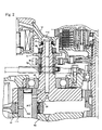
- Fig. 1 is a sectional view of a crank shaft and a crank case in an internal combustion engine, illustrating a lubricating oil feed passage structure formed in the crank shaft according to an embodiment of the present invention; and
- Fig. 2 is a sectional view of a crank shaft and a crank case in an internal combustion engine, illustrating a conventional lubricating oil feed passage structure formed in the crank shaft.
-
- An embodiment of the present invention will be described hereinunder with reference to Fig. 1.
- A lubricating oil feed passage structure in a crank shaft according to the first embodiment of the present invention, which is illustrated in Fig. 1, is applied to a
crank shaft 1 of an overhead camshaft type V-shaped 2-cyliner internal combustion engine mounted on such a vehicle as a motorcycle. Thecrank shaft 1 is supported by acrank case 3 which is divided into upper and lower halves through two right and left bearings 2 (only the right-hand one is shown) serving as main bearings.Passages 4 for feeding a lubricating oil to thebearings 2 are formed respectively in support portions for thebearings 2 of thecrank case 3. - The
crankshaft 1 comprisescrankpins 1a,crank journals 1b.crank arms 1c, and balanceweights 1d, which are formed integrally by molding. Large end portions 5a of connectingrods 5, whose small end portions are pivotally secured to piston pins mounted to pistons of the cylinders, are respectively connected to thecrank pins 1a in an adjacent manner. More specifically, the large end portions 5a of the connecting rods are slidably fitted on outer peripheries of thecrank pins 1a serving as connection surfaces for connection with the connectingrods 5, throughbearings 6 fixed to inner peripheries of thecrank pins 1a. A lubricating oil is fed between the connectingrods 5 and the connection surfaces of thecrank pins 1a to diminish a frictional resistance induced between the two. - On the other hand, a reciprocating motion of each piston transferred through the associated connecting
rod 5 is converted to a rotational motion and the resulting torque of thecrank shaft 1 is transmitted to a rear wheel via a multiple-disc friction clutch 7, a constant meshtype gear transmission 8 and a driving chain. In this case, the transfer of the torque between thecrank shaft 1 and the multiple-disc friction clutch 7 is performed by a primary reduction mechanism comprising aprimary driving gear 9 splined to anend portion 1e of thecrank shaft 1 and a primary drivengear 11 connected to a clutch housing of the multiple-disc friction clutch 7 through a damper. - The
primary driving gear 9 has aprimary sub gear 9a connected thereto through an elastic member which is a spring for the purpose of eliminating backlash between it and the primary drivengear 11. Theprimary sub gear 9a is fitted on an outer periphery of aboss portion 9b formed on a thrust washer 31 side to be described later of theprimary driving gear 9. An end face of theprimary sub gear 9a and that of theboss portion 9b are cable of coming into abutment against the thrust washer 31. - The
end portion 1e of thecrank shaft 1 is constituted of a portion of thecrank shaft 1 which portion extends from the right-hand crank journal 1b toward a right-handcrank case cover 12. An outer periphery of theshaft end portion 1e has an outer peripheral portion 1f and a spline portion 1g, the outer peripheral portion if being positioned near acrank journal 1b and having a smooth circumferential surface. The spline portion 1g is formed as a small-diameter portion which extends from the outer peripheral portion 1f toward an end face 1h of theshaft end portion 1e and which has an outside diameter smaller than that of the outer peripheral portion 1f. The spline portion 1g comprises a plurality of spline grooves and spline ridges formed in parallel with a crank shaft axis L1. Thus, the outside diameter of the outer peripheral portion 1f is set larger than that of the spline ridges of the spline portion 1g. - Onto the outer periphery of the
shaft end portion 1e are mounted a cam shaft drivingtiming gear 10 and theprimary driving gear 9 successively from the right-hand crank journal 1b side, thetiming gear 10 and theprimary driving gear 9 havingspline portions spline portions shaft end portion 1e. Thus, bothgears crank shaft 1 so as to be unmovable in the rotating direction of the crank shaft and rotatable integrally with the crank shaft. Movement ofbath gears crank center bolt 30 which is mounted to theshaft end portion 1e and which will be described later. Since thespline portion 1b of thecrank shaft 1 and thespline portions gears crank shaft 1 is transmitted to bothgears gears crank shaft 1 is transferred and which transmits the torque to the cam shaft or the multiple-disc friction clutch 7. - On the inner periphery of the
timing gear 10 and at a position close to the right-hand crank journal 1b is formed an inner peripheral portion 10a having a smooth circumferential surface to be fitted with the outer peripheral portion 1f which is formed at theshaft end portion 1e. Since the outer peripheral portion 1f and the inner peripheral portion 10a are fitted together by clearance fit, there is performed an accurate centering of thetiming gear 10 with respect to thecrank shaft 1. Further, a more accurate centering can be effected by subjecting the outer and inner peripheral portions 1f, 10a to an abrasive machining. By this centering operation, vibration of the timing gear relative to thecrank shaft 1 is prevented and hence the generation of noise based on the vibration is suppressed. Besides, the work for fitting the outer peripheral portion 1f and the inner peripheral portion 10a is easy because of clearance fit. Further, since the outside diameter of the outer peripheral portion 1f is larger than that of the spline portion 1g of thecrank shaft 1, the fitting of the outer and inner peripheral portions 1f, 10a can be done without being influenced by splining at the spline portion 1g, thus permitting a more accurate centering work. On the other hand, the rotation of thetiming gear 10 is transmitted through a series of gears to a cam shaft installed in the cylinder head and intake and exhaust valves are driven in accordance with rotation of the cam shaft. - The following description is now provided about the lubricating oil passage.
- A bottomed,
stepped hole 21 extending from the end face 1h of theshaft end portion 1e toward thecrank arm 1c, having a small-diameter portion and a large-diameter portion and having an axis aligned with the crank shaft axis L1, is formed by drilling from the end face 1h of theshaft end portion 1e. The small-diameter portion of thestepped hole 21 is located at a position close to thecrank arm 1c (close to the bottom), while the large-diameter portion of thehole 21 is positioned close to the end face 1h of theshaft end portion 1e (close to the open end). The peripheral wall of the large-diameter portion is internally threaded at a portion thereof close to the open end and thecrank center bolt 30, which will be described later, comes into engagement with the internal threads. Thestepped hole 21 thus formed constitutes a first lubricatingoil passage 21 for feeding the lubricating oil to the foregoing connection surface of thecrank pin 1a. - In the
crank pin 1a is formed abottomed hole 23 by drilling from the right-hand side of thecrank arm 1c, thebottomed hole 23 extending from the right-hand side of the right-hand crank arm 1c toward thecrank pin 1a and having an axis parallel to a crank pin axis L2. The axis of thehole 23 lies on a plane including both crank pin axis L2 and crank shaft axis L1 and is positioned on the side opposite to the crank shaft axis L1 with respect to the crank pin axis L2. The diameter of thehole 23 is set larger than the diameter of the small-diameter portion of the steppedhole 21 and thus thehole 23 functions to store the lubricating oil which has entered the hole. Therefore, the lubricating oil can be fed stably to the foregoing connection surface of thecrank pin 1a through a fourth lubricating oil passage 24 which will be described later. The portion of thehole 23 closer to the open end with respect to a portion where thehole 23 crosses a second lubricating oil passage 22 to be described later. Thehole 23 thus formed constitutes a thirdlubricating oil passage 23 for feeding the lubricating oil to the foregoing connection surface of thecrank pin 1a. - A passage portion of the third
lubricating oil passage 23 positioned closer to the open end with respect to a cup-like member 25 is set larger in diameter than the other passage portion of the thirdlubricating oil passage 23 and in it circumferential wall is formed an annular groove in which aclip 26 is fitted by virtue of an elastic force thereof. Theclip 26 prevents the cup-like member 25 from coming off the thirdlubricating oil passage 23. - Further, a hole 22 is formed by drilling from an outer peripheral portion of the
crank arm 1c close to the crankpin 1a, the hole 22 extending from the outer peripheral portion toward thebalance weight 1d through the thirdlubricating oil passage 23 and reaching an innermost portion of the first lubricating oil passage 21 (the bottom of the small-diameter portion of the stepped hole 21). The hole 22 has an axis perpendicular to the axes of the first and thirdlubricating oil passages hole 21. A portion of the hole 22 located closer to the open end with respect to the portion where the hole 22 crosses the thirdlubricating oil passage 23 is closed by aball member 27 which is a sealing plug. The hole 22 thus formed constitutes a second lubricating oil passage 22 for feeding the lubricating oil to the foregoing connection surface of thecrank pin 1a. - Further, by drilling from the connection surface side of each crank
pin 1a there are formed two holes 24 which are open to the thirdlubricating oil passage 23 in the portion corresponding to the large end portion 5a of each connectingrod 5. The holes 24 constitutes a fourth lubricating oil passage 24 for feeding the lubricating oil to the connection surface. With the lubricating oil flowing out from the fourth lubricating oil passage 24 there is effected lubrication between thebearing 6 at the large end portion 5a of the connectingrod 5 and the connection surface. - The above first to fourth lubricating
oil passages crank shaft 1. The portion of the firstlubricating oil passage 21 adjacent to an end face of ashaft portion 30a of thecrank center bolt 30 corresponds to an inlet end of the lubricating oil passage formed in the crank shaft, while an open end of the fourth lubricating oil passage 24 located on the foregoing connection surface side corresponds to an outlet end of the lubricating oil passage formed in the crank shaft. - External threads formed on the
shaft portion 30a of thecrank center bolt 30 come into threaded engagement with the internal threads formed in the large-diameter portion of the steppedhole 21, whereby thecrank center bolt 30 is secured to theend portion 1e of thecrank shaft 1. The head of thecrank center bolt 30 comprises a hexagonal prism portion adjacent to theshaft portion 30a and formed with aflange portion 30b and a cylindrical portion 30d extending axially from the hexagonal prism portion 30c. A lip portion of anoil seal 34 comes into sliding contact with the outer periphery of the cylindrical portion 30d as will be described later, so the outer periphery of the cylindrical portion 30d is subjected to abrasive machining for smoothing the sliding contact portion. - In the
crank center bolt 30 is formed a throughhole 30e from an end face of the cylindrical portion 30d of the bolt head toward the end face of theshaft portion 30a, the throughhole 30e having an axis aligned with the axis of thecrank center bolt 30 and hence aligned with the axis of the crank shaft axis L1. Thetrough hole 30e thus formed constitutes a lubricatingoil introducing passage 30e which is connected to the inlet end of the lubricating oil passage formed in thecrank shaft 1. - The
crank center bolt 30, with a thrust washer 31 fitted thereon, is brought into threaded engagement with the internal threads of the steppedhole 21 by means of a tool which is applied to the hexagonal prism portion 30c. As a result of thecrank center bolt 30 being tightened, an end face of thetiming gear 10 on thecrank journal 1b side comes into abutment against an end face of thecrank journal 1b, an end face of thetiming gear 10 on theprimary driving gear 9 side and an end face of theprimary driving gear 9 on thetiming gear 10 side come into abutment against each other, and an end face of theprimary driving gear 9 on the thrust washer 31 side and an end face of theboss portion 9b on the thrust washer 31 side come into abutment against the thrust washer 31, whereby thetiming gear 10 and theprimary driving gear 9 both mounted on theshaft end portion 1e are prevented from moving in the crank axis L1 direction, as noted previously. - Moreover, as the
crank center bolt 30 is tightened, a tensile force is exerted between the external threads and theflange 30b of the crank center bolt, so that in this portion there occurs a slight elongation within an elastic region. Consequently, an elastic force based on the elongation acts on the internal threads of the large-diameter portion of the steppedhole 21 and also on the external threads of thecrank center bolt 30 which are threadedly engaged with each other, so that the toughness against loosening of thebolt 30 is improved and thebolt 30 becomes difficult to loosen. Accordingly, the inhibited state of thetiming gear 10 and theprimary driving gear 9 from moving in the crank axis L1 direction is ensured more positively. - Further, with both
gears bolt 30, aslight gap 32 is formed between the end face 1h of theend portion 1e of thecrank shaft 1 and the thrust washer 31. In order that the lubricating oil may be fed through thegap 32 to the fitted portion between the inner periphery of theprimary sub gear 9a and the outer periphery of theboss portion 9b of theprimary driving gear 9, a first oil hole 30f, which is open not only to the lubricatingoil introducing passage 30e but also to thegap 32, is formed in theshaft portion 30a of thecrank center bolt 30 in the vicinity of the portion where the thrust washer 31 is fitted thereon, the first oil hole 30f being formed perpendicularly to the axis of the lubricatingoil introducing passage 30e, and also formed is asecond oil hole 9d extending radially through the fitted portion of theboss portion 9b. Therefore, a portion of the lubricating oil flowing through the lubricatingoil introducing passage 30e passes through the first oil hole 30f and thegap 32, further passes through thesecond oil hole 9d and is fed to the fitted portion of theprimary sub gear 9a and theboss portion 9b of theprimary driving gear 9. - Thus, the
crank center bolt 30 not only functions as a fixing member for fixing thetiming gear 10 and theprimary driving gear 9 as torque transfer members but also functions as a lubricating oil introducing member for introducing the lubricating oil to the lubricating oil passage formed in the crank shaft. In this embodiment, therefore, as compared with the prior art shown in Fig. 1, the length of theend portion 1e of thecrank shaft 1 is smaller by a distance corresponding to the projecting length of thecrank center bolt 30 from the end face 1h of theshaft end portion 1e. Consequently, the length of the firstlubricating oil passage 21 formed in thecrank shaft 1 also becomes shorter than in the prior art, thus facilitating machining for the same passage. - Inside the right-hand crank case cover 12 is formed a recess as a lubricating oil chamber 33. With the right-
hand cover 12 attached to the crankcase 3, the lubricating oil chamber 33 is positioned on the crank shaft axis L1 and hence on the axis of the lubricatingoil introducing passage 30e formed in thecrank center bolt 30 and is open toward thecrank shaft 1, which position of the lubricating oil chamber 33 permits the cylindrical portion 30d of the crank center bolt head to get into the same chamber. In this state, theoil seal 34 is fixed to an open end portion of the lubricating oil chamber 33 and the lip portion thereof is in sliding contact with the polished outer periphery of the cylindrical portion 30d positioned within the lubricating oil chamber 33 to keep liquid-tight between the open end portion of the lubricating oil chamber 33 and the cylindrical portion 30d, thus preventing the lubricating oil present in the lubricating oil chamber 33 from leaking through the outer periphery of the cylindrical portion 30d. - Now, a description will be given below about how the lubricating oil flows in this embodiment.
- The lubricating oil, which is pressurized by the oil pump, passes through the filter and the passage formed in the right-hand crank
case cover 12, then is fed into the lubricating oil chamber 33 formed in thecover 12 and is stored therein. The lubricating oil present in the lubricating oil chamber 33 flows through the lubricatingoil introducing passage 30e formed in thecrank center bolt 30, enters the firstlubricating oil passage 21 formed in thecrank shaft 1, further passes through the second, third and fourth lubricatingoil passages 22, 23, 24, then is discharged to the connection surface of thecrank pin 1a and is fed between thebearing 6 at the large end portion 5a of each connectingrod 5 as a sliding portion and the connection surface of thecrank pin 1a. A portion of the lubricating oil introduced into the lubricatingoil introducing passage 30e, as described previously, passes through the first oil hole 30f, thegap 32 and thesecond oil hole 9d and is fed to the fitted portion of theprimary sub gear 9a and theboss portion 9b of theprimary driving gear 9. - Since this embodiment is constructed as above, there are attained the following effects.
- Since the lubricating oil is taken into the lubricating oil passage formed in the
crank shaft 1 through the lubricatingoil introducing passage 30e formed in thecrank center bolt 30 which projects in the crank shaft axis L1 direction from the end face 1h of theend portion 1e of thecrank shaft 1, the length of theend portion 1e of thecrank shaft 1 becomes smaller than in the prior art by a distance corresponding to the projecting length of thecrank center bolt 30 from the end face 1h of theend portion 1e of thecrank shaft 1. Consequently, the lubricating oil passage formed in theshaft end portion 1e becomes shorter and so the machining for the lubricating oil passage to be formed in thecrank shaft 1 becomes easier. - Since the lubricating
oil introducing passage 30e is formed in thecrank center bolt 30 which prevents thetiming gear 10 and theprimary driving gear 9 from moving in the crank shaft axis L1 direction, thecrank center bolt 30 as a single member not only functions as a fixing member for fixing thetiming gear 10 and theprimary driving gear 9 but also functions as a lubricating introducing member for introducing the lubricating oil into the lubricating oil passage, thus making it possible to reduce the number of components used. - Since the
timing gear 10 and theprimary driving gear 9 are tightened by thecrank center bolt 30, thebolt 30 becomes difficult to loosen under the action of an elastic force which is created in thebolt 30 itself, so that the movement of bothgears - Since the cylindrical portion 30d of the head of the
crank center bolt 30 gets into the lubricating oil chamber 33 formed in the right-hand crankcase cover 12, it is possible to easily cope with even a case where the spacing between the end face 1h of the crankshaft end portion 1e and the lubricating oil chamber 33 differs depending on the model of a vehicle, without the need of changing thecrank shaft 1, by providing a plurality ofcrank center bolts 30 different in length of the cylindrical portion 30d. - Since the lip portion of the
oil seal 34 comes into sliding contact with the polished portion of the cylindrical portion 30d at the head of thecrank center bolt 30, it is possible to surely prevent the lubricating oil from leaking through the outer periphery of the cylindrical portion 30d. - A portion of the lubricating oil which has been introduced into the lubricating
oil introducing passage 30e formed in thecrank center bolt 30 passes through the first oil hole 30f,gap 32 andsecond oil hole 9d and is fed to the fitted portion of theprimary sub gear 9a and the boss portion of theprimary driving gear 9. Thus, the fitted portion can be lubricated by such a simple constitution. - By attaching a lubricating oil introducing member to an end portion of a crank shaft, the crank shaft end portion is to be shortened to facilitate machining for a lubricating oil passage to be formed in the crank shaft.
- A lubricating oil feed passage in a
crank shaft 1, comprising lubricatingoil passages crank shaft 1 and having an inlet end and an outlet end which is open to a connection surface of acrank pin 1a for connection with a connectingrod 5, abolt 30 secured to anend portion 1e of thecrank shaft 1 so as to project in an axial direction of the crank shaft from an end face 1h of theshaft end portion 1e, and a lubricatingoil introducing passage 30e formed axially through thebolt 30 and connected to the inlet end.
Claims (3)
- A lubricating oil feed passage structure in a crank shaft(1), comprising:a lubricating oil passage (21,22,23,24,) formed in the crank shaft (1) which has a crank pin (1a) with a connecting rod (5) connected thereto, said lubricating oil passage (21,22,23,24) having an inlet end and an outlet end which is open to a connection surface for connection with said connecting rod (5) of said crank pin (1a);a lubricating oil introducing member (30) mounted at an end portion of said crank shaft (1) so as to project in an axial direction of the crank shaft (1) from an end face of said crank shaft end portion (1e); anda lubricating oil introducing passage (30e) formed axially through said lubricating oil introducing member (30) and connected to said inlet end.
- A lubricating oil feed passage structure in a crank shaft (1) according to claim 1, wherein said lubricating oil introducing member (30) is a bolt (30) which prevents a torque transfer member (9,9a,10) from moving in the axial direction of the crank shaft (1), said torque transfer member being mounted to said crank shaft end portion.
- A lubricating oil feed passage structure in a crank shaft (1) according to claim 2, wherein a head of said bolt (30) has a cylindrical portion (30d), said cylindrical portion (30d) being positioned within a lubricating oil chamber (33) formed in a crank case cover (12).
Applications Claiming Priority (2)
| Application Number | Priority Date | Filing Date | Title |
|---|---|---|---|
| JP2512599 | 1999-02-02 | ||
| JP02512599A JP4169414B2 (en) | 1999-02-02 | 1999-02-02 | Crankshaft lubricating oil supply passage structure |
Publications (2)
| Publication Number | Publication Date |
|---|---|
| EP1026371A1 true EP1026371A1 (en) | 2000-08-09 |
| EP1026371B1 EP1026371B1 (en) | 2005-03-09 |
Family
ID=12157236
Family Applications (1)
| Application Number | Title | Priority Date | Filing Date |
|---|---|---|---|
| EP00100661A Expired - Lifetime EP1026371B1 (en) | 1999-02-02 | 2000-01-13 | Lubricating oil feed passage structure in crank shaft |
Country Status (5)
| Country | Link |
|---|---|
| US (1) | US6334422B1 (en) |
| EP (1) | EP1026371B1 (en) |
| JP (1) | JP4169414B2 (en) |
| CN (1) | CN1106498C (en) |
| DE (1) | DE60018490T2 (en) |
Cited By (2)
| Publication number | Priority date | Publication date | Assignee | Title |
|---|---|---|---|---|
| EP2163737A1 (en) * | 2008-09-11 | 2010-03-17 | Suzuki Motor Corporation | Oil passage structure of engine |
| CN108351020A (en) * | 2015-11-12 | 2018-07-31 | 五十铃自动车株式会社 | Scissor gears are for structure for oil |
Families Citing this family (10)
| Publication number | Priority date | Publication date | Assignee | Title |
|---|---|---|---|---|
| JP4160242B2 (en) * | 2000-09-12 | 2008-10-01 | 本田技研工業株式会社 | Engine power transmission structure |
| JP4427700B2 (en) * | 2000-09-13 | 2010-03-10 | アイシン・エィ・ダブリュ株式会社 | Hybrid drive unit |
| WO2003071102A1 (en) * | 2002-02-20 | 2003-08-28 | Yamaha Hatsudoki Kabushiki Kaisha | Lubrication device of engine |
| US7096846B1 (en) | 2005-07-01 | 2006-08-29 | Harley-Davidson Motor Company Group, Inc. | Engine and transmission case assembly |
| ES2485496T3 (en) * | 2005-10-07 | 2014-08-13 | Combi Corporation | Cushion to retain a child's posture and structure using the same cushion |
| JP4438732B2 (en) * | 2005-10-20 | 2010-03-24 | トヨタ自動車株式会社 | Power transmission mechanism |
| JP4954133B2 (en) * | 2008-03-31 | 2012-06-13 | 本田技研工業株式会社 | Oil passage structure |
| CN101892883B (en) * | 2010-08-02 | 2012-09-26 | 浙江钱江摩托股份有限公司 | Lubricating device for crankshaft connecting mechanism of motorcycle |
| DE102013113818A1 (en) * | 2013-12-11 | 2015-06-11 | Dr. Ing. H.C. F. Porsche Aktiengesellschaft | internal combustion engine |
| US11549443B2 (en) | 2020-08-28 | 2023-01-10 | Pratt & Whitney Canada Corp. | Sealing arrangement with vent for an engine component with a service port |
Citations (5)
| Publication number | Priority date | Publication date | Assignee | Title |
|---|---|---|---|---|
| GB191115380A (en) * | 1911-03-27 | 1911-11-16 | Rupert John Isaacson | An Improved System of Lubricating Internal Combustion Engines. |
| GB105387A (en) * | 1916-04-10 | 1917-04-10 | Theodore Livinus Reepm Urville | Improvements in and relating to Internal Combustion Engines. |
| GB2086532A (en) * | 1980-10-28 | 1982-05-12 | Faulkner Frederick Arthur | Crankshaft lubrication system |
| DE3338506A1 (en) * | 1983-10-22 | 1985-05-02 | Volkswagenwerk Ag, 3180 Wolfsburg | Bearing lubrication device |
| EP0816643A1 (en) * | 1996-07-03 | 1998-01-07 | Toyota Jidosha Kabushiki Kaisha | Hydraulic actuator in an internal combustion engine |
Family Cites Families (1)
| Publication number | Priority date | Publication date | Assignee | Title |
|---|---|---|---|---|
| JP3627830B2 (en) | 1995-08-11 | 2005-03-09 | 本田技研工業株式会社 | Mission gear misassembly prevention structure |
-
1999
- 1999-02-02 JP JP02512599A patent/JP4169414B2/en not_active Expired - Fee Related
-
2000
- 2000-01-13 EP EP00100661A patent/EP1026371B1/en not_active Expired - Lifetime
- 2000-01-13 DE DE60018490T patent/DE60018490T2/en not_active Expired - Lifetime
- 2000-02-02 US US09/496,589 patent/US6334422B1/en not_active Expired - Fee Related
- 2000-02-02 CN CN00101852.3A patent/CN1106498C/en not_active Expired - Fee Related
Patent Citations (5)
| Publication number | Priority date | Publication date | Assignee | Title |
|---|---|---|---|---|
| GB191115380A (en) * | 1911-03-27 | 1911-11-16 | Rupert John Isaacson | An Improved System of Lubricating Internal Combustion Engines. |
| GB105387A (en) * | 1916-04-10 | 1917-04-10 | Theodore Livinus Reepm Urville | Improvements in and relating to Internal Combustion Engines. |
| GB2086532A (en) * | 1980-10-28 | 1982-05-12 | Faulkner Frederick Arthur | Crankshaft lubrication system |
| DE3338506A1 (en) * | 1983-10-22 | 1985-05-02 | Volkswagenwerk Ag, 3180 Wolfsburg | Bearing lubrication device |
| EP0816643A1 (en) * | 1996-07-03 | 1998-01-07 | Toyota Jidosha Kabushiki Kaisha | Hydraulic actuator in an internal combustion engine |
Cited By (6)
| Publication number | Priority date | Publication date | Assignee | Title |
|---|---|---|---|---|
| EP2163737A1 (en) * | 2008-09-11 | 2010-03-17 | Suzuki Motor Corporation | Oil passage structure of engine |
| US8307804B2 (en) | 2008-09-11 | 2012-11-13 | Suzuki Motor Corporation | Oil passage structure of engine |
| CN108351020A (en) * | 2015-11-12 | 2018-07-31 | 五十铃自动车株式会社 | Scissor gears are for structure for oil |
| EP3376075A4 (en) * | 2015-11-12 | 2019-07-03 | Isuzu Motors Limited | SHAFT OIL FEEDING STRUCTURE OF JAWS |
| US10626976B2 (en) | 2015-11-12 | 2020-04-21 | Isuzu Motors Limited | Scissor gear oil supplying structure |
| CN108351020B (en) * | 2015-11-12 | 2021-03-02 | 五十铃自动车株式会社 | Oil supply structure for scissors gear |
Also Published As
| Publication number | Publication date |
|---|---|
| CN1263981A (en) | 2000-08-23 |
| DE60018490T2 (en) | 2005-07-28 |
| JP2000220422A (en) | 2000-08-08 |
| US6334422B1 (en) | 2002-01-01 |
| DE60018490D1 (en) | 2005-04-14 |
| CN1106498C (en) | 2003-04-23 |
| EP1026371B1 (en) | 2005-03-09 |
| JP4169414B2 (en) | 2008-10-22 |
Similar Documents
| Publication | Publication Date | Title |
|---|---|---|
| US5067456A (en) | Hypocycloid engine | |
| EP1026371B1 (en) | Lubricating oil feed passage structure in crank shaft | |
| JP5634160B2 (en) | Support structure for crankshaft of internal combustion engine | |
| US6481389B2 (en) | Piston oil-cooling device in an engine | |
| CA2474470C (en) | Engine valve train device | |
| US5253547A (en) | Balancer device for in-line engine | |
| US8662253B2 (en) | Lubricating oil feeding structure | |
| CA2474986C (en) | Engine lubrication system | |
| JP4044049B2 (en) | TECHNICAL FIELD The present invention relates to an engine balancer device having two balancer shafts. | |
| US4997409A (en) | Wrapping type transmission structure for internal combustion engines | |
| JP2008519217A (en) | Crank mechanism | |
| US1948340A (en) | Groove for main bearings | |
| US6736023B1 (en) | Torque transmitting device | |
| US9157365B2 (en) | Internal combustion engine with balancer | |
| CN109209552B (en) | Crankshaft for internal combustion engine | |
| CA2474472C (en) | Engine fastening structure | |
| EP2034220A2 (en) | V-belt type continuously variable transmission | |
| JP2000220423A (en) | Lubricating oil passage structure for crankshaft | |
| JPH0151644B2 (en) | ||
| JP7432191B2 (en) | Internal combustion engine with mass balance gear with two balance shafts | |
| JPH0318761Y2 (en) | ||
| JP2832608B2 (en) | Balancer shaft drive for internal combustion engine | |
| JPH0334510Y2 (en) | ||
| JP6327055B2 (en) | Engine lubrication oil supply structure | |
| CS271191B1 (en) | Lubricating device for crank-mechanismes big-end bearing with four-stroke internal combustion engine |
Legal Events
| Date | Code | Title | Description |
|---|---|---|---|
| PUAI | Public reference made under article 153(3) epc to a published international application that has entered the european phase |
Free format text: ORIGINAL CODE: 0009012 |
|
| AK | Designated contracting states |
Kind code of ref document: A1 Designated state(s): DE FR IT |
|
| AX | Request for extension of the european patent |
Free format text: AL;LT;LV;MK;RO;SI |
|
| 17P | Request for examination filed |
Effective date: 20010126 |
|
| AKX | Designation fees paid |
Free format text: DE FR IT |
|
| 17Q | First examination report despatched |
Effective date: 20040109 |
|
| GRAP | Despatch of communication of intention to grant a patent |
Free format text: ORIGINAL CODE: EPIDOSNIGR1 |
|
| GRAS | Grant fee paid |
Free format text: ORIGINAL CODE: EPIDOSNIGR3 |
|
| GRAA | (expected) grant |
Free format text: ORIGINAL CODE: 0009210 |
|
| AK | Designated contracting states |
Kind code of ref document: B1 Designated state(s): DE FR IT |
|
| REF | Corresponds to: |
Ref document number: 60018490 Country of ref document: DE Date of ref document: 20050414 Kind code of ref document: P |
|
| PLBE | No opposition filed within time limit |
Free format text: ORIGINAL CODE: 0009261 |
|
| STAA | Information on the status of an ep patent application or granted ep patent |
Free format text: STATUS: NO OPPOSITION FILED WITHIN TIME LIMIT |
|
| ET | Fr: translation filed | ||
| 26N | No opposition filed |
Effective date: 20051212 |
|
| PGFP | Annual fee paid to national office [announced via postgrant information from national office to epo] |
Ref country code: IT Payment date: 20070519 Year of fee payment: 8 |
|
| PGFP | Annual fee paid to national office [announced via postgrant information from national office to epo] |
Ref country code: FR Payment date: 20070109 Year of fee payment: 8 |
|
| REG | Reference to a national code |
Ref country code: FR Ref legal event code: ST Effective date: 20081029 |
|
| PG25 | Lapsed in a contracting state [announced via postgrant information from national office to epo] |
Ref country code: FR Free format text: LAPSE BECAUSE OF NON-PAYMENT OF DUE FEES Effective date: 20080131 |
|
| PG25 | Lapsed in a contracting state [announced via postgrant information from national office to epo] |
Ref country code: IT Free format text: LAPSE BECAUSE OF NON-PAYMENT OF DUE FEES Effective date: 20080113 |
|
| PGFP | Annual fee paid to national office [announced via postgrant information from national office to epo] |
Ref country code: DE Payment date: 20110105 Year of fee payment: 12 |
|
| PG25 | Lapsed in a contracting state [announced via postgrant information from national office to epo] |
Ref country code: DE Free format text: LAPSE BECAUSE OF NON-PAYMENT OF DUE FEES Effective date: 20120801 |
|
| REG | Reference to a national code |
Ref country code: DE Ref legal event code: R119 Ref document number: 60018490 Country of ref document: DE Effective date: 20120801 |