EP1025933A1 - Immersion nozzle - Google Patents
Immersion nozzle Download PDFInfo
- Publication number
- EP1025933A1 EP1025933A1 EP98943036A EP98943036A EP1025933A1 EP 1025933 A1 EP1025933 A1 EP 1025933A1 EP 98943036 A EP98943036 A EP 98943036A EP 98943036 A EP98943036 A EP 98943036A EP 1025933 A1 EP1025933 A1 EP 1025933A1
- Authority
- EP
- European Patent Office
- Prior art keywords
- nozzle
- molten steel
- immersion nozzle
- twisted
- flow
- Prior art date
- Legal status (The legal status is an assumption and is not a legal conclusion. Google has not performed a legal analysis and makes no representation as to the accuracy of the status listed.)
- Granted
Links
Images


Classifications
-
- B—PERFORMING OPERATIONS; TRANSPORTING
- B22—CASTING; POWDER METALLURGY
- B22D—CASTING OF METALS; CASTING OF OTHER SUBSTANCES BY THE SAME PROCESSES OR DEVICES
- B22D11/00—Continuous casting of metals, i.e. casting in indefinite lengths
- B22D11/10—Supplying or treating molten metal
-
- B—PERFORMING OPERATIONS; TRANSPORTING
- B22—CASTING; POWDER METALLURGY
- B22D—CASTING OF METALS; CASTING OF OTHER SUBSTANCES BY THE SAME PROCESSES OR DEVICES
- B22D41/00—Casting melt-holding vessels, e.g. ladles, tundishes, cups or the like
- B22D41/50—Pouring-nozzles
- B22D41/507—Pouring-nozzles giving a rotating motion to the issuing molten metal
Definitions
- the present invention relates to an immersion nozzle used in continuous casting of molten steel.
- an immersion nozzle used in continuous casting in the case of billet casting, a straight type immersion nozzle is frequently used to avoid discharged molten steel from colliding with a mold wall at high speed since a distance between a nozzle and the mold wall is short. Further, in the case of slab continuous casting, a bifurcated nozzle having outlet on the narrow side of a mold is used.
- molten steel is discharged mainly in the right downward direction and inclusions and bubbles are accompanied deeply in the mold and therefore, there poses a problem in which inclusions and bubbles are caught in cast steel or liable to deposit on the bent portion at the lower side of the mold to cause a defect. Further, discharged molten steel is mainly directed downward and therefore, temperature drop of molten steel at the meniscus is significant, melting of mold powder becomes insufficient and lubricity between the mold and a solidified shell is deteriorated to thereby cause surface defect of cast steel.
- the meniscus is referred to an interface between molten steel and mold powder in the mold.
- electromagnetic stirring of molten steel by a magnetic field system has been proposed for the purpose of controlling molten steel flow in the mold.
- controlling of the molten steel flow by electromagnetic stirring is effective, this process cannot be regarded as sufficient countermeasure for high speed continuous casting requested recently.
- the electromagnetic stirrer is very expensive and the location of installing the system is disposed in a severe environment exposed to high temperature and maintenance and repair of the system is not easy.
- the inventors have carried out various investigation to provide an immersion nozzle to solve the problems of the conventional technology mentioned above and conceived to provide swirlling to motlen steel flow in an immersion nozzle and carried out water model experiments.
- an outlet pattern can preferably be controlled such as a reduction in a maximum outlet velocity, uniform discharge from a total of an outlet and this result has been presented (Iron & Steel VoL.80 No.10 P754-758(1994), ISIJ (The Iron and Steel Institute of Japan) International VoL.34 No.11 P883-888(1994)).
- swirling is provided by installing a swirling blade at an upper portion of the nozzle.
- a used swirling blade is constituted of a circular disc in a doughnut-like shape having an inner diameter the same as the inner diameter of the nozzle and is provided with 12 of blades each having slope for constituting a swirling flow from water flowed into the nozzle.
- the inventors have groped various methods of providing swirling to actual molten steel flow.
- the shape of a swirling blade used in the water model experiment is complicated, manufacture by a material capable of withstanding molten steel at high temperature has been extremely difficult and the material cannot withstand physical impact of molten steel flow.
- the inventors have conceived an element which is constructed in a twisted-tape shape which has a simple shape such that it can be manufactured by a material withstanding molten steel flow and which can provide sufficient swirling. With this shape, the element can be manufactured easily and withstand impact of molten steel, further, more or less additional processing after producing and installation thereof in a nozzle are facilitated. Further, the inventors have found that excellent swirling can be provided to molten steel flow in the nozzle by properly setting the twisted-tape shape and completed the present invention.
- the present invention is constituted by an immersion nozzle having an element in a twisted-tape shape to provide swirling in molten steel flow in the nozzle.
- the molten steel flow in the mold is controlled, a distance of invasion of inclusions and bubbles becomes short and trapping thereof in cast steel is prevented. Further, an effect of preventing inclusions from adhering to an inner wall of the nozzle is also achieved.
- excellent swirling is provided by constituting the shape of the element in a twisted-tape shape such that a ratio L/D of length L and width D falls in a range of 0.5 through 2 and a twisted angle ⁇ is 100° or more.
- the element in a twisted-tape shape of this invention is applicable to an immersion nozzle of both a straight type and a bifurcated type.
- discharge of molten steel is not directed to right downward but mainly in a skew downward direction by which invasion of inclusions and bubbles can be reduced.
- molten steel flow can preferably be provided in the direction of the meniscus and lowering of temperature of molten steel at the meniscus can be reduced.
- the effect is further significant when the inner wall of the vertical section constitutes a figure of a divergent arc with a radius of curvature in a range of 30 through 300 mm.
- the maximum outlet velocity of molten steel can be reduced and therefore, collision of an outflow and a turned flow from the narrow side of the mold is alleviated and meniscus fluctuation can be prevented.
- molten steel flow in the mold can further preferably be controlled and the temperature drop of molten steel of the meniscus can be reduced.
- the effect becomes further significant when the inner wall of the vertical section is constituted by a figure of a divergent arc with a radius of curvature in a range of 30 through 300 mm.
- a structure without bottom can be constituted in the bifurcated nozzle which is further preferable in view of preventing adhesion of inclusions.
- an immersion nozzle having a structure of blowing gas into molten steel flow provided with swirling in the nozzle according to each type of the nozzles mentioned above.
- the gas blowing type immersion nozzle an effect of trapping and taking out inclusions in molten steel and floating it up in a mold is substantially prolonged.
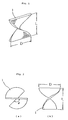
- Fig. 1 shows an element 1 in a twisted-tape shape for providing swirling to molten steel flow in a nozzle which is the most important feature of the present invention.
- the width D of the element 1 is determined by an inner diameter of the nozzle and the length L and the twisted angle ⁇ of the element 1 may be set in a range by which sufficient swirling is provided to molten steel flow to achieve the effect of the present invention.
- the twisted angle ⁇ is an angle which is produced by twisting an article in a plane tape shape.
- Table 1 shows a case in which the width D and the twisted angle ⁇ of the element in a twisted-tape shape are made constant and the length L is varied and Table 2 shows a case in which the width D and the length L are made constant and the twisted angle ⁇ is varied.
- No. 4 of Table 1 and No. 10 of Table 2 are the same as each other.
- flow rates at central upper and lower portion of an outlet are measured and a maximum flow rate value of each sample is designated by an index with that of No. 1 as 100.
- the flow rate is measured by a laser doppler velocimeter.
- the ratio L/D falls in a range of 0.5 through 2.0, particularly preferably, 0.8 through 1.5.
- L/D is less than 0.5, flow of molten steel in the nozzle is considerably hindered and when L/D exceeds 2.0, sufficient swirling cannot be provided.
- L/D falls in a range of 0.5 through 2.0, an effect of reducing the maximum outlet velocity is significant.
- the twisted angle ⁇ is preferable at 100° or more, particularly preferable at 120° or more. Even when ⁇ exceeds 180° , the effect of providing swirling, the outflow angle and the maximum outlet velocity stay substantially equivalent. It is preferable that ⁇ is 180° or less in consideration of easiness in manufacturing the element. When an angle more than 180° is needed,it is preferable to obtain the necessary angle by installing two pieces or more of the elements, although the necessary angle may be obtained by one piece of the element.
- Material of the element in a twisted-tape shape is not particularly limited so far as the shape can be fabricated and the material can withstand molten steel flow ,so that the material may be such that generally used in the main body of a nozzle or may be other refractory material.
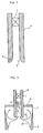
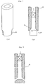
- the immersion nozzle having the element in a twisted-tape shape according to the present invention can preferably be used in any of a straight type nozzle and a bifurcated nozzle. Examples of the immersion nozzles are respectively shown in Fig. 3 and Fig. 4.
- molten steel in the mold 7 is preferably stirred and therefore, there is achieved an effect in which quality of cast steel becomes uniform.
- Fig. 5 by constituting an inner wall of the nozzle 4 at an outlet 5 of molten steel in a shape of a divergent arc in the vertical section,there is achieved higher quality cast steel.
- the effect is particularly achieved when a radius R of curvature in a circular arc shape of the inner wall of the outlet 5 is 30 through 300 mm.
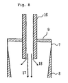
- molten steel flow is mainly constituted by a flow 17 in the right downward direction and a flow 18 in a slightly skew downward direction is observed.
- the immersion nozzle of the present invention by providing swirling to molten steel flow in the nozzle, the effect of reducing adhesion of inclusions on the inner wall of the nozzle is achieved and the effect of preventing adhesion of inclusions becomes further significant by blowing inert gas or the like to molten steel provided with swirling.
- the blown gas is simply moved along with molten steel and takes out inclusions which is brought into contact with the gas.
- the immersion nozzle of the present invention the blown gas is converged on the axial direction of the nozzle since the molten steel flow swirls.
- the bubbles form a film of high density in a conical shape and accordingly, a probability of bringing bubbles into contact with inclusions in molten steel is enhanced.
- the inclusions are not adhered onto the inner wall of the nozzle but are trapped and taken out by bubbles and are floated up in the mold.
- the effect of preventing adhesion of inclusions the nozzle is scarce to clog and therefore, life of the nozzle is prolonged.
- the effect is achieved by supplying gas at a low flow rate and at low pressure and therefore, it is also economical.
- Fig. 8 shows an example of an immersion nozzle according to the present invention having a gas blowing system 15.
- the immersion nozzle according to the present invention provides swirling to molten steel flow in the nozzle by the element in a twisted-tape shape and can preferably control molten steel flow in the mold, however, the invention does not exclude using of an electromagnetic stirrer together with.
- Nozzles shown in Table 3 as straight type immersion nozzles are tested.
- the used immersion nozzles are made of alumina-graphite material and samples having an outer diameter of 105 mm, an inner diameter of 60 mm and a length of 700 mm are molded by a cold isostatic press and in respect of samples other than those of Embodiment 1 and Comparative example 1, the inner wall of the outlet in each thereof is manufactured in a diverging shape.
- An element in a twisted-tape shape is constituted by a sintered boron-nitride, a step is formed on the inner wall of the nozzle in shaping the nozzle and the previously manufactured element is installed to be caught by the step.
- the length 48 mm
- the thickness of the element is 10 mm.
- the billet of horizontal section of 170 mm x 170 mm is cast at the speed of 2.5 m/min, and rates of inner defect and surface defect of cast steel are measured. Further, temperature of molten steel in the tundish and temperature of molten steel at the meniscus are measured and the temperature difference is shown in Table 3. The measurement is carried out similarly in respect of comparative examples.
- both the inner defect and the surface defect of cast steel are reduced to 1/2 or less. Further, by forming the inner wall of the outlet by the divergent arc shape, temperature drop of molten steel at the meniscus is reduced, further reduction is observed both in the inner and the surface defects and in case the radius of curvature is 30 through 300 mm, the defect rate is about 1/6 through 1/10 of that of Comparative example 1.
- Nozzles under the specification shown in Table 4 as bifurcated immersion nozzles are tested.
- the main body of the nozzle is made of alumina-graphite material and samples having the inner diameter of 74 mm, the outer diameter of 130 mm and the length of 500 mm are shaped by a cold isostatic press.
- the element in a twisted-tape shape is manufactured by a sintered boron-nitride, a step is formed on the inner wall of the nozzle in shaping the nozzle and the element is installed to the step.
- the width 80 mm
- the twisted angle 180°
- the thickness 10 mm.
- each immersion nozzle is installed at the bottome of a tundish having a capacity of 50 tons and Al killed steel is cast at a speed of 2 m/min.
- the test is similarly carried out also in respect of comparative example. The respective test results are shown in Table 4.
- Embodiment Comparative example 7 3 Twisted-tape element Present None Velocity variation at meniscus (m/s) 0.07 ⁇ 0.11 0.05 ⁇ 0.22 Surface defect rate of cast steel (number/100cm 2 0.06 0.46 State of bent portion on lower side of mold after casting 1,250 tons Almost no deposition of inclusions Deposition of inclusions by about 1/6 of cast thickness
- Table 5 shows the test result with regard to presence or absence of a bottom of a bifurcated immersion nozzle.
- the material and dimensions of the nozzle of main body and the material and shape of the element in a twisted-tape shape are the same as those in Table 4.
- Each immersion nozzle is installed at the bottom of a tundish having a capacity of 50 tons and Al killed steel is cast. The test is similarly carried out in respect of comparative example.
- Table 5 shows the test results.
- the element By installing the element in a twisted-tape shape according to the present invention, defects of cast steel are reduced, prolongation in the life of the nozzle by preventing adhesion of inclusions on the inner wall of the nozzle is observed and by constituting the structure without bottom, both the rate of surface defect and life until clogging of the nozzle are substantually prolonged.
- the life of the nozzle without bottom is provided with the life near to twice of that of the nozzle having the bottom and about three times of that of the nozzle without element in a twisted-tape shape.
- Embodiments Comparative example 8 9 4 Bottom structure of nozzle With bottom Without bottom With bottom Twisted-tape element Present Present None Surface defect rate of cast steel (number/100cm 2 ) 0.06 0.03 0.25 State of bent portion on lower side of mold after casting 2,000 tons Almost no deposition of inclusions Almost no deposition of inclusions Deposition of inclusions by about 1/6 of cast thickness State of adhering inclusions on inner wall of nozzle after casting 2,000 tons Slight adhesion at vicinity of bottom portion No adhesion both at straight portion & vicinity of outlet Significant adhesion almost to nozzle clogging Life index until nozzle clogging 182 290 100
- Table 6 shows the test result investigating on the shape of the inner wall near the outlet for bifurcated immersion nozzles.
- the used immersion nozzles are made of alumina-graphite material of the outer diameter of 130 mm, the inner diameter of 75 mm and the length of 700 mm, are shaped by a cold isostatic press and the outlets are made such that the inner wall near the outlet is constituted in a divergent arc shape having predetermined radius of curvature in the vertical section except those in Embodiment 10 and Comparative example 6.
- the element in a twisted-tape shape is manufactured by sintered boron-nitride, a step is formed on the inner wall of each of the nozzles in shaping the nozzles and a previously fabricated element is installed to the step.
- the thickness of all of the elements is 10 mm.
- Temperature of molten steel in the tundish and temperature of molten steel at the meniscus are measured and temperature difference is shown in Table 6. Measurement is similarly carried out in respect of comparative examples.
- the inner defect is measured by a number of defects on a face produced by cutting the cast steel end of the slab by 40 mm, the surface defect is measured by the number of defects on a face produced by shaving the cast steel face by 5 mm and both of them are indicated by the index with a result of Comparative example 1 as 1.
- the inner wall By installing the element in a twisted-tape shape according to the present invention, defects are reduced. The effect becomes further significant by constituting the inner wall near a hollowed portion for injecting molten steel in a divergent arc shape in the vertical section.
- a circular arc shape having the radius of curvature of 30 through 300 mm compared with the sample in which the inner wall is not constituted by a divergent arc shape, the inner defects are reduced to about 1/3 and the surface defects are reduced to about 1/2.
- the inner defects When the inner wall is formed in a divergent arc shape, compared also with a sample without element in a twisted-tape like shape, the inner defects are reduced to about 1/5 and the surface defects are reduced to about 1/3 through 1/4.
- Embodiments Comparative examples 10 11 12 13 14 15 5 6 Type of twisted-tape element A A A A A B None None Structure of bottom of the nozzle Without bottom Without bottom Without bottom Without bottom Without bottom With-bottom Without bottom Withbottom Withbottom Radius of curvature of inner wall of outlet (mm) 50 150 250 350 150 150 Inner defect index 0.55 0.20 0.20 0.20 0.20 0.30 1.00 0.85 Surface defect index 0.60 0.30 0.25 0.35 0.45 0.40 1.00 0.70 Temperature difference of molten steel btw. in the tundish & meniscus (° C) 24 14 11 15 18 11 25 22 Remark) The inner wall of the outlet is not formed in a divergent shape in Example 10 and Comparative example 6.
- the sample under a specification the same as that of Embodiment 7 (Embodiment 16) and the sample provided with the gas blowing system are made (Embodiment 17).
- the immersion nozzles are mounted to a tundish having a capacity of 50 tons and casting is carried out blowing Ar gas.
- the immersion nozzle having a specification the sane as that of Comparative example 3 is similarly used
- the present invention is an immersion nozzle installed an element in a twisted-tape shape to provide swirlling to motlen steel flow in continuous casting of molten steel, with a purpose of controlling molten steel flow and preventing adhesion of inclusions on an inner wall of an immersion nozzle in a mold in pursuit of high quality of cast steel.As a result, without using an expensive device such as an electromagnetic stirrer, an immersion nozzle capable of achieving the above-described object and contributing to high quality of cast steel and prolongation of life of the nozzle is obtained.
- the immersion nozzle having the element in a twisted-tape shape according to the present invention is applicable both to a straight type and a bifurcated type.
Landscapes
- Engineering & Computer Science (AREA)
- Mechanical Engineering (AREA)
- Continuous Casting (AREA)
- Casting Support Devices, Ladles, And Melt Control Thereby (AREA)
- Treatment Of Steel In Its Molten State (AREA)
- Nozzles (AREA)
Abstract
Description
| No. | 1 | 2 | 3 | 4 | 5 | 6 | 7 |
| Shape of twisted-tape shape element | |||||||
| width D (mm) | 40 | 40 | 40 | 40 | 40 | 40 | |
| length L (mm) | 12 | 20 | 40 | 60 | 80 | 100 | |
| L/D | 0.3 | 0.5 | 1.0 | 1.5 | 2.0 | 2.5 | |
| twisted angle (° ) | 180 | 180 | 180 | 180 | 180 | 180 | |
| Generation of swirling flow | none | ▵ | ○ | o ○ | o ○ | ○ | ▵ |
| Outflow angle(° ) | 0 | 10 | 40 | 45 | 45 | 40 | 10 |
| Index of maximum outlet velocity | 100 | 80 | 42 | 25 | 30 | 36 | 78 |
| Remarks) No. 1 is not provided with the element in a
twisted-tape shape. Generation of swirling flow o ○: water in pipe is flowed by being swirled uniformly ○: water is flowed by being swirled substantially uniformly although disturbance is caused partially ▵: water is flowed while causing almost no swirling Outflow angle : Angle of outflow water. Right downward direction is set to 0° . Index of maximum outlet velocity : Index with that of No. 1 as 100. |
| No. | 8 | 9 | 10 | 11 | 12 | 13 |
| Shape of twisted-tape shape element | ||||||
| width D (mm) | 40 | 40 | 40 | 40 | 40 | 40 |
| length L (mm) | 40 | 40 | 40 | 40 | 40 | 40 |
| L/D | 1.0 | 1.0 | 1.0 | 1.0 | 1.0 | 1.0 |
| twisted angle (° ) | 90 | 120 | 180 | 200 | 240 | 270 |
| Generation of swirling flow | ▵ | ○ | o ○ | o ○ | o ○ | o ○ |
| Outflow angle(° ) | 5 | 40 | 45 | 45 | 45 | 45 |
| Index of maximum outlet velocity | 86 | 36 | 25 | 25 | 25 | 25 |
| Embodiments | Comparative examples | |||||||
| 1 | 2 | 3 | 4 | 5 | 6 | 1 | 2 | |
| Type of twisted-tape element | A | A | A | A | A | B | None | None |
| Radius of curvature of inner wall of outlet (mm) | 50 | 150 | 250 | 350 | 150 | 150 | ||
| Inner defect index | 0.40 | 0.15 | 0.15 | 0.15 | 0.15 | 0.15 | 1.00 | 0.95 |
| Surface defect index | 0.50 | 0.10 | 0.08 | 0.15 | 0.40 | 0.08 | 1.00 | 0.08 |
| Temperature difference of molten steel between in the tundish and meniscus (° C) | 20 | 13 | 9 | 12 | 16 | 10 | 25 | 23 |
| Remark) The inner wall of the outlet is not formed in a
divergent shape in |
| Embodiment | Comparative example | |
| 7 | 3 | |
| Twisted-tape element | Present | None |
| Velocity variation at meniscus (m/s) | 0.07 ∼ 0.11 | 0.05 ∼ 0.22 |
| Surface defect rate of cast steel (number/100cm2 | 0.06 | 0.46 |
| State of bent portion on lower side of mold after casting 1,250 tons | Almost no deposition of inclusions | Deposition of inclusions by about 1/6 of cast thickness |
| Embodiments | Comparative example | ||
| 8 | 9 | 4 | |
| Bottom structure of nozzle | With bottom | Without bottom | With bottom |
| Twisted-tape element | Present | Present | None |
| Surface defect rate of cast steel (number/100cm2) | 0.06 | 0.03 | 0.25 |
| State of bent portion on lower side of mold after casting 2,000 tons | Almost no deposition of inclusions | Almost no deposition of inclusions | Deposition of inclusions by about 1/6 of cast thickness |
| State of adhering inclusions on inner wall of nozzle after casting 2,000 tons | Slight adhesion at vicinity of bottom portion | No adhesion both at straight portion & vicinity of outlet | Significant adhesion almost to nozzle clogging |
| Life index until nozzle clogging | 182 | 290 | 100 |
| Embodiments | Comparative examples | |||||||
| 10 | 11 | 12 | 13 | 14 | 15 | 5 | 6 | |
| Type of twisted-tape element | A | A | A | A | A | B | None | None |
| Structure of bottom of the nozzle | Without bottom | Without bottom | Without bottom | Without bottom | Without bottom | With-bottom | Without bottom | Withbottom |
| Radius of curvature of inner wall of outlet (mm) | 50 | 150 | 250 | 350 | 150 | 150 | ||
| Inner defect index | 0.55 | 0.20 | 0.20 | 0.20 | 0.20 | 0.30 | 1.00 | 0.85 |
| Surface defect index | 0.60 | 0.30 | 0.25 | 0.35 | 0.45 | 0.40 | 1.00 | 0.70 |
| Temperature difference of molten steel btw. in the tundish & meniscus (° C) | 24 | 14 | 11 | 15 | 18 | 11 | 25 | 22 |
| Remark) The inner wall of the outlet is not formed in a divergent shape in Example 10 and Comparative example 6. |
Claims (10)
- An immersion nozzle having an element in a twisted-tape shape for providing swirling to molten steel flow in the immersion nozzle.
- An immersion nozzle according to Claim 1, wherein a shape of an element in the twisted-tape shape is constituted by a ratio L/D of a length L to a width D of 0.5 through 2 and a twisted angle of 100° or more.
- An immersion nozzle according to Claim 1 or 2, wherein the immersion nozzle is a straight type nozzle and has an element in the twisted-tape shape for providing swirling to the molten steel flow in the immersion nozzle.
- An immersion nozzle according to Claim 3, wherein an inner wall at an outlet of molten steel of the straight type nozzle is formed in a divergent arc shape in a vertical section.
- An immersion nozzle according to Claim 4, wherein the inner wall is formed in the divergent arc shape with a radius of curvature in a range of 30 through 300 mm in the vertical section.
- An immersion nozzle according to Claim 1 or 2, wherein the immersion nozzle is of a bifurcated type and has an element in the twisted-tape shape for providing swirling to the molten steel flow in the immersion nozzle.
- An immersion nozzle according to Claim 6, wherein an inner wall near an outlet of molten steel of the bifurcated immersion nozzle is formed in a divergent arc shape in a vertical section.
- An immersion nozzle according to Claim 7, wherein the inner wall is formed in the divergent arc shape with a radius of curvature in a range of 30 through 300 mm in the vertical section.
- An immersion nozzle according to Claim 6, wherein a nozzle has a structure without bottom.
- An immersion nozzle according to Claims 1, 3 and 6, further comprising a structure of blowing gas from an inner wall of the nozzle.
Applications Claiming Priority (11)
| Application Number | Priority Date | Filing Date | Title |
|---|---|---|---|
| JP27502997 | 1997-09-22 | ||
| JP27503197 | 1997-09-22 | ||
| JP27503097 | 1997-09-22 | ||
| JP27502997 | 1997-09-22 | ||
| JP27503097 | 1997-09-22 | ||
| JP27503197 | 1997-09-22 | ||
| JP14237898 | 1998-05-08 | ||
| JP14237898 | 1998-05-08 | ||
| JP14237798 | 1998-05-08 | ||
| JP14237798 | 1998-05-08 | ||
| PCT/JP1998/004205 WO1999015291A1 (en) | 1997-09-22 | 1998-09-18 | Immersion nozzle |
Publications (3)
| Publication Number | Publication Date |
|---|---|
| EP1025933A1 true EP1025933A1 (en) | 2000-08-09 |
| EP1025933A4 EP1025933A4 (en) | 2001-11-07 |
| EP1025933B1 EP1025933B1 (en) | 2003-11-19 |
Family
ID=27527643
Family Applications (1)
| Application Number | Title | Priority Date | Filing Date |
|---|---|---|---|
| EP98943036A Expired - Lifetime EP1025933B1 (en) | 1997-09-22 | 1998-09-18 | Immersion nozzle |
Country Status (9)
| Country | Link |
|---|---|
| US (1) | US6435385B1 (en) |
| EP (1) | EP1025933B1 (en) |
| KR (1) | KR100527353B1 (en) |
| CN (1) | CN1186147C (en) |
| AU (1) | AU739918B2 (en) |
| CA (1) | CA2300923C (en) |
| DE (2) | DE1025933T1 (en) |
| RU (1) | RU2203771C2 (en) |
| WO (1) | WO1999015291A1 (en) |
Cited By (3)
| Publication number | Priority date | Publication date | Assignee | Title |
|---|---|---|---|---|
| EP1106286A1 (en) * | 1999-12-02 | 2001-06-13 | SMS Demag AG | Process and device for feeding molten metal from a tundish through a submerged tube in a continuous casting mould |
| EP1759789A1 (en) * | 2005-08-30 | 2007-03-07 | Krosakiharima Corporation | Pouring tube structure and pouring method for uphill casting |
| WO2013160476A3 (en) * | 2012-04-26 | 2014-05-30 | Sms Concast Ag | Refractory casting tube for a mould for continuously casting molten metal |
Families Citing this family (16)
| Publication number | Priority date | Publication date | Assignee | Title |
|---|---|---|---|---|
| JP3524507B2 (en) | 2001-02-23 | 2004-05-10 | 住友金属工業株式会社 | Steel continuous casting method |
| US6932250B2 (en) * | 2003-02-14 | 2005-08-23 | Isg Technologies Inc. | Submerged entry nozzle and method for maintaining a quiet casting mold |
| JP3861861B2 (en) * | 2003-08-04 | 2006-12-27 | 住友金属工業株式会社 | Immersion nozzle for continuous casting and continuous casting method |
| WO2005018851A1 (en) * | 2003-08-22 | 2005-03-03 | Krosakiharima Corporation | Immersion nozzle for continuous casting of steel and meethod for continuous casting of steel using the immersion nozzle |
| WO2005070589A1 (en) * | 2004-01-23 | 2005-08-04 | Sumitomo Metal Industries, Ltd | Immersion nozzle for continuous casting and continuous casting method using the immersion nozzle |
| ES2658172T3 (en) | 2009-11-06 | 2018-03-08 | Nippon Steel & Sumitomo Metal Corporation | Continuous casting procedure for molten metal |
| JP5505969B2 (en) * | 2010-03-15 | 2014-05-28 | 黒崎播磨株式会社 | Long nozzle |
| DE102010062892B4 (en) * | 2010-12-13 | 2023-07-06 | Robert Bosch Gmbh | Flow grid for use in a flow tube of a flowing fluid medium |
| EP2835193A1 (en) * | 2013-08-05 | 2015-02-11 | Refractory Intellectual Property GmbH & Co. KG | Refractory ceramic nozzle |
| CN108436071B (en) * | 2018-05-31 | 2024-05-14 | 东北大学秦皇岛分校 | Spin-flow long nozzle for continuous casting |
| CN108526453B (en) * | 2018-05-31 | 2024-05-14 | 东北大学秦皇岛分校 | Spin flow immersion nozzle for continuous casting |
| CN110801955A (en) * | 2018-08-05 | 2020-02-18 | 大连理工大学 | Nozzle with torsional variable-section spray hole |
| CN110801946A (en) * | 2018-08-05 | 2020-02-18 | 大连理工大学 | A nozzle with a twisted rounded rectangular nozzle |
| CN110801951A (en) * | 2018-08-05 | 2020-02-18 | 大连理工大学 | Nozzle with multi-hole parallel type spray holes |
| EP3900855A1 (en) * | 2020-04-21 | 2021-10-27 | Refractory Intellectual Property GmbH & Co. KG | Rotatable insert and submerged nozzle |
| CN117718467B (en) * | 2023-12-14 | 2024-06-28 | 东北大学 | An electromagnetic swirl enhanced submerged nozzle |
Family Cites Families (11)
| Publication number | Priority date | Publication date | Assignee | Title |
|---|---|---|---|---|
| US4142682A (en) * | 1977-02-04 | 1979-03-06 | Bowen Norman D | Spray nozzle insert |
| JPS61126953A (en) * | 1984-11-22 | 1986-06-14 | Nippon Steel Corp | Method for stirring molten steel in continuous casting mold |
| JPS626957U (en) * | 1985-06-28 | 1987-01-16 | ||
| JPS63108966A (en) * | 1986-10-24 | 1988-05-13 | Hiromitsu Nakagawa | Immersion nozzle of tundish |
| SU1754322A1 (en) * | 1989-12-25 | 1992-08-15 | Уральский государственный институт по проектированию металлургических заводов | Continuous casting nozzle |
| JPH0474820A (en) * | 1990-07-17 | 1992-03-10 | Sumitomo Metal Ind Ltd | Method for accelerating degassing of molten steel |
| JPH04304308A (en) * | 1991-03-29 | 1992-10-27 | Sumitomo Metal Ind Ltd | Method for promoting degassing in molten metal |
| JPH05185192A (en) * | 1992-01-13 | 1993-07-27 | Kawasaki Steel Corp | Immersed nozzle for continuous casting |
| JPH07303949A (en) * | 1994-03-18 | 1995-11-21 | Kawasaki Steel Corp | Continuous casting method and nozzle for continuous casting |
| JP2986688B2 (en) * | 1994-07-29 | 1999-12-06 | 東芝セラミックス株式会社 | Gas blowing nozzle |
| JPH08215809A (en) * | 1994-12-14 | 1996-08-27 | Nippon Steel Corp | Nozzles for continuous casting of steel |
-
1998
- 1998-09-18 WO PCT/JP1998/004205 patent/WO1999015291A1/en not_active Ceased
- 1998-09-18 DE DE1025933T patent/DE1025933T1/en active Pending
- 1998-09-18 EP EP98943036A patent/EP1025933B1/en not_active Expired - Lifetime
- 1998-09-18 DE DE69819931T patent/DE69819931T2/en not_active Expired - Lifetime
- 1998-09-18 US US09/509,124 patent/US6435385B1/en not_active Expired - Fee Related
- 1998-09-18 CA CA002300923A patent/CA2300923C/en not_active Expired - Fee Related
- 1998-09-18 RU RU2000110122/02A patent/RU2203771C2/en not_active IP Right Cessation
- 1998-09-18 CN CNB988093146A patent/CN1186147C/en not_active Expired - Fee Related
- 1998-09-18 AU AU90955/98A patent/AU739918B2/en not_active Ceased
- 1998-09-18 KR KR10-2000-7002162A patent/KR100527353B1/en not_active Expired - Fee Related
Cited By (3)
| Publication number | Priority date | Publication date | Assignee | Title |
|---|---|---|---|---|
| EP1106286A1 (en) * | 1999-12-02 | 2001-06-13 | SMS Demag AG | Process and device for feeding molten metal from a tundish through a submerged tube in a continuous casting mould |
| EP1759789A1 (en) * | 2005-08-30 | 2007-03-07 | Krosakiharima Corporation | Pouring tube structure and pouring method for uphill casting |
| WO2013160476A3 (en) * | 2012-04-26 | 2014-05-30 | Sms Concast Ag | Refractory casting tube for a mould for continuously casting molten metal |
Also Published As
| Publication number | Publication date |
|---|---|
| EP1025933A4 (en) | 2001-11-07 |
| CA2300923C (en) | 2006-09-12 |
| CN1271303A (en) | 2000-10-25 |
| DE69819931T2 (en) | 2004-07-29 |
| EP1025933B1 (en) | 2003-11-19 |
| CN1186147C (en) | 2005-01-26 |
| KR100527353B1 (en) | 2005-11-08 |
| KR20010023516A (en) | 2001-03-26 |
| AU9095598A (en) | 1999-04-12 |
| RU2203771C2 (en) | 2003-05-10 |
| CA2300923A1 (en) | 1999-04-01 |
| AU739918B2 (en) | 2001-10-25 |
| WO1999015291A1 (en) | 1999-04-01 |
| DE1025933T1 (en) | 2001-02-08 |
| DE69819931D1 (en) | 2003-12-24 |
| US6435385B1 (en) | 2002-08-20 |
Similar Documents
| Publication | Publication Date | Title |
|---|---|---|
| EP1025933B1 (en) | Immersion nozzle | |
| USRE45093E1 (en) | Submerged entry nozzle with installable parts | |
| US4819840A (en) | Refractory submerged pouring nozzle | |
| WO1997048512A1 (en) | Submerged nozzle for the continuous casting of thin slabs | |
| CN108247033A (en) | A kind of continuous casting production eddy flow filling pipe end | |
| JP3515762B2 (en) | Immersion nozzle for continuous casting and continuous casting method | |
| US6557623B2 (en) | Production method for continuous casting cast billet | |
| JPH03110048A (en) | Tundish stopper | |
| US7140521B2 (en) | Nozzle for continuous casting | |
| KR102228648B1 (en) | Sliding nozzle | |
| SK166399A3 (en) | Method and device for producing slabs | |
| CA1082421A (en) | Single piece annular nozzle to prevent alumina buildup during continuous casting of al-killed steel | |
| KR20230002935A (en) | Immersion nozzle with rotatable insert | |
| KR100485404B1 (en) | Partial Immersion Nozzle for Continuous Casting of Thin Slabs | |
| JPH04238658A (en) | Immersion nozzle for continuous casting | |
| US4117959A (en) | Method and single piece annular nozzle to prevent alumina buildup during continuous casting of al-killed steel | |
| JP4421136B2 (en) | Continuous casting method | |
| USRE30343E (en) | Method and single piece annular nozzle to prevent alumina buildup during continuous casting of Al-killed steel | |
| RU1787670C (en) | Method of continuous casting of thin slabs | |
| KR101969105B1 (en) | Nozzle | |
| WO2005021187A1 (en) | Submerged entry nozzle for continuous casting | |
| TW202529911A (en) | Immersion nozzle for continuous casting and continuous steel casting method | |
| JP3039821B2 (en) | Immersion nozzle for continuous casting and method of pouring molten steel | |
| JPH05318057A (en) | Immersion nozzle for continuous casting | |
| JPS58116961A (en) | Discharging method of molten metal |
Legal Events
| Date | Code | Title | Description |
|---|---|---|---|
| PUAI | Public reference made under article 153(3) epc to a published international application that has entered the european phase |
Free format text: ORIGINAL CODE: 0009012 |
|
| 17P | Request for examination filed |
Effective date: 20000306 |
|
| AK | Designated contracting states |
Kind code of ref document: A1 Designated state(s): DE FR GB |
|
| EL | Fr: translation of claims filed | ||
| DET | De: translation of patent claims | ||
| A4 | Supplementary search report drawn up and despatched |
Effective date: 20010926 |
|
| AK | Designated contracting states |
Kind code of ref document: A4 Designated state(s): DE FR GB |
|
| 17Q | First examination report despatched |
Effective date: 20021016 |
|
| GRAH | Despatch of communication of intention to grant a patent |
Free format text: ORIGINAL CODE: EPIDOS IGRA |
|
| GRAS | Grant fee paid |
Free format text: ORIGINAL CODE: EPIDOSNIGR3 |
|
| RAP1 | Party data changed (applicant data changed or rights of an application transferred) |
Owner name: YOKOYA, SHINICHIRO Owner name: HARA, SHIGETA Owner name: MARUKAWA, KATSUKIYO |
|
| RIN1 | Information on inventor provided before grant (corrected) |
Inventor name: YOKOYA, SHINICHIRO Inventor name: HARA, SHIGETA Inventor name: MARUKAWA, KATSUKIYO |
|
| GRAA | (expected) grant |
Free format text: ORIGINAL CODE: 0009210 |
|
| AK | Designated contracting states |
Kind code of ref document: B1 Designated state(s): DE FR GB |
|
| REG | Reference to a national code |
Ref country code: GB Ref legal event code: FG4D |
|
| RAP2 | Party data changed (patent owner data changed or rights of a patent transferred) |
Owner name: KYUSHU REFRACTORIES CO., LTD. Owner name: MARUKAWA, KATSUKIYO |
|
| RIN2 | Information on inventor provided after grant (corrected) |
Inventor name: YOKOYA, SHINICHIRO Inventor name: HARA, SHIGETA Inventor name: MARUKAWA, KATSUKIYO |
|
| REF | Corresponds to: |
Ref document number: 69819931 Country of ref document: DE Date of ref document: 20031224 Kind code of ref document: P |
|
| ET | Fr: translation filed | ||
| PLBE | No opposition filed within time limit |
Free format text: ORIGINAL CODE: 0009261 |
|
| STAA | Information on the status of an ep patent application or granted ep patent |
Free format text: STATUS: NO OPPOSITION FILED WITHIN TIME LIMIT |
|
| 26N | No opposition filed |
Effective date: 20040820 |
|
| PGFP | Annual fee paid to national office [announced via postgrant information from national office to epo] |
Ref country code: DE Payment date: 20101123 Year of fee payment: 13 |
|
| PGFP | Annual fee paid to national office [announced via postgrant information from national office to epo] |
Ref country code: GB Payment date: 20110923 Year of fee payment: 14 Ref country code: FR Payment date: 20111005 Year of fee payment: 14 |
|
| GBPC | Gb: european patent ceased through non-payment of renewal fee |
Effective date: 20120918 |
|
| REG | Reference to a national code |
Ref country code: FR Ref legal event code: ST Effective date: 20130531 |
|
| REG | Reference to a national code |
Ref country code: DE Ref legal event code: R119 Ref document number: 69819931 Country of ref document: DE Effective date: 20130403 |
|
| PG25 | Lapsed in a contracting state [announced via postgrant information from national office to epo] |
Ref country code: DE Free format text: LAPSE BECAUSE OF NON-PAYMENT OF DUE FEES Effective date: 20130403 Ref country code: GB Free format text: LAPSE BECAUSE OF NON-PAYMENT OF DUE FEES Effective date: 20120918 |
|
| PG25 | Lapsed in a contracting state [announced via postgrant information from national office to epo] |
Ref country code: FR Free format text: LAPSE BECAUSE OF NON-PAYMENT OF DUE FEES Effective date: 20121001 |