EP1024585A2 - Drive arrangement for functional elements about several independent axes and method for producing the same - Google Patents
Drive arrangement for functional elements about several independent axes and method for producing the same Download PDFInfo
- Publication number
- EP1024585A2 EP1024585A2 EP00101033A EP00101033A EP1024585A2 EP 1024585 A2 EP1024585 A2 EP 1024585A2 EP 00101033 A EP00101033 A EP 00101033A EP 00101033 A EP00101033 A EP 00101033A EP 1024585 A2 EP1024585 A2 EP 1024585A2
- Authority
- EP
- European Patent Office
- Prior art keywords
- drive unit
- arrangement according
- pinion
- base body
- drive
- Prior art date
- Legal status (The legal status is an assumption and is not a legal conclusion. Google has not performed a legal analysis and makes no representation as to the accuracy of the status listed.)
- Withdrawn
Links
Images


Classifications
-
- H—ELECTRICITY
- H02—GENERATION; CONVERSION OR DISTRIBUTION OF ELECTRIC POWER
- H02K—DYNAMO-ELECTRIC MACHINES
- H02K7/00—Arrangements for handling mechanical energy structurally associated with dynamo-electric machines, e.g. structural association with mechanical driving motors or auxiliary dynamo-electric machines
- H02K7/14—Structural association with mechanical loads, e.g. with hand-held machine tools or fans
-
- H—ELECTRICITY
- H02—GENERATION; CONVERSION OR DISTRIBUTION OF ELECTRIC POWER
- H02K—DYNAMO-ELECTRIC MACHINES
- H02K1/00—Details of the magnetic circuit
- H02K1/06—Details of the magnetic circuit characterised by the shape, form or construction
- H02K1/12—Stationary parts of the magnetic circuit
- H02K1/18—Means for mounting or fastening magnetic stationary parts on to, or to, the stator structures
- H02K1/185—Means for mounting or fastening magnetic stationary parts on to, or to, the stator structures to outer stators
-
- H—ELECTRICITY
- H02—GENERATION; CONVERSION OR DISTRIBUTION OF ELECTRIC POWER
- H02K—DYNAMO-ELECTRIC MACHINES
- H02K11/00—Structural association of dynamo-electric machines with electric components or with devices for shielding, monitoring or protection
- H02K11/20—Structural association of dynamo-electric machines with electric components or with devices for shielding, monitoring or protection for measuring, monitoring, testing, protecting or switching
- H02K11/21—Devices for sensing speed or position, or actuated thereby
-
- H—ELECTRICITY
- H02—GENERATION; CONVERSION OR DISTRIBUTION OF ELECTRIC POWER
- H02K—DYNAMO-ELECTRIC MACHINES
- H02K7/00—Arrangements for handling mechanical energy structurally associated with dynamo-electric machines, e.g. structural association with mechanical driving motors or auxiliary dynamo-electric machines
- H02K7/10—Structural association with clutches, brakes, gears, pulleys or mechanical starters
- H02K7/102—Structural association with clutches, brakes, gears, pulleys or mechanical starters with friction brakes
- H02K7/1021—Magnetically influenced friction brakes
- H02K7/1023—Magnetically influenced friction brakes using electromagnets
- H02K7/1025—Magnetically influenced friction brakes using electromagnets using axial electromagnets with generally annular air gap
-
- H—ELECTRICITY
- H02—GENERATION; CONVERSION OR DISTRIBUTION OF ELECTRIC POWER
- H02K—DYNAMO-ELECTRIC MACHINES
- H02K7/00—Arrangements for handling mechanical energy structurally associated with dynamo-electric machines, e.g. structural association with mechanical driving motors or auxiliary dynamo-electric machines
- H02K7/10—Structural association with clutches, brakes, gears, pulleys or mechanical starters
- H02K7/116—Structural association with clutches, brakes, gears, pulleys or mechanical starters with gears
-
- H—ELECTRICITY
- H02—GENERATION; CONVERSION OR DISTRIBUTION OF ELECTRIC POWER
- H02K—DYNAMO-ELECTRIC MACHINES
- H02K16/00—Machines with more than one rotor or stator
-
- H—ELECTRICITY
- H02—GENERATION; CONVERSION OR DISTRIBUTION OF ELECTRIC POWER
- H02K—DYNAMO-ELECTRIC MACHINES
- H02K2201/00—Specific aspects not provided for in the other groups of this subclass relating to the magnetic circuits
- H02K2201/18—Machines moving with multiple degrees of freedom
Definitions
- the invention relates to an arrangement for driving functional elements around several independent axes and a method for their production, in particular for those applications in which drives with high torque and low mass and small space requirements are required, such as drives of optical and / or stabilized platforms or of multi-dimensional handling devices of robots or manipulators.
- drive units are usually used, which consist of a motor with a coupled gear and a drive pinion.
- An exception are so-called direct drives, where the rotor of the motor is mounted directly on the shaft to be driven. Due to the limited achievable torques of such direct drives, their use remains limited to very special applications. In applications that require fast, precise positioning of moving elements with a relatively large mass, the use of direct drives with high torque is mostly impossible due to weight and volume restrictions.
- the invention has for its object a new way to drive Functional elements to find several independent axes, with low mass and low space requirements high torque, great accuracy in the Positioning and stabilizing the movement element in the respective axis guaranteed.
- the object is achieved in an arrangement for driving functional elements around a plurality of independent axes, in which at least one drive unit is provided for aligning the functional elements for each axis of rotation and a base body is provided as a carrier for the functional elements and the drive units, in that the drive unit with respect to the support and stabilization function of the stator is fully integrated in the material and in the supporting structure of the base body, the base body having essentially cylindrical recesses for receiving all components of the drive unit and means for rigid fixation at least with respect to tangential forces and moments of the stator Counteracting the rotary movement of the rotor of the drive unit are provided in the support structure of the base body.
- the fixation of the drive unit in the supporting structure of the base body is advantageously carried out in a form-fitting manner.
- the use of adapters is suitable for this purpose, the adapters being arranged in grooves which the drive unit and the cylindrical recess have in the longitudinal direction of the cylindrical recess of the base body.
- the drive unit is secured against rotation and additionally against axial displacement by pins in the supporting structure of the base body.
- the drive unit is non-positively fixed in the supporting structure of the base body.
- the drive unit is preferably fixed in the supporting structure of the base body by means of screws.
- the drive unit is advantageously provided with a gear that transmits the rotary movement to the respective functional element in order to achieve a speed reduction of the functional element. It is advantageous if the gearbox is partially integrated in the structure of the base body, the drive unit having an output shaft with pinion and for each of the functional elements there is a ring gear with a large radius for transmitting the rotary movement from the pinion to the functional element and stored in the base body or is led. For certain applications it may be necessary that the drive unit contains an additional gear in front of the output shaft provided with the pinion. This is expediently a coaxial transmission, whereby the compactness and symmetry of the entire drive unit is retained.
- the drive unit When the drive unit is inserted into the supporting structure of the base body, there are various options for mounting the pinion that drives the (large) ring gear of the functional element.
- the pinion In a first variant, the pinion is overhung.
- a more stable and therefore more suitable option for many applications is to mount the pinion on both sides.
- the pinion While the pinion is supported either with a bearing of the motor shaft or the bearing of the output shaft of the additional gear of the drive unit, there are design options for the counter bearing of the pinion, which differ in terms of their production costs and the stability that can be achieved.
- the requirements for adjustment and production are significantly lower if the pinion counter bearing is mounted in an auxiliary structure connected to the drive unit.
- the auxiliary structure is advantageously attached to the housing of the additional gear.
- a mechanically clamped pinion arrangement is advantageously used for a play-free power transmission from the pinion to the (large) ring gear of the functional element.
- the mechanically clamped pinion arrangement preferably consists of two partial pinions with the same toothing, one partial pinion rigid and the other rotatably fastened in close proximity to the output shaft of the drive unit, and a spring element (torsion spring, tension spring or pressure element) located between the partial pinions is tensioned by rotating the rotatable partial pinion is locked when both pinions engage in the (large) ring gear of the functional element.
- the mechanically clamped pinion arrangement has a conventional pinion on the output shaft of the drive unit and two additional gear elements with identical teeth and two gears each, via which the pinion of the output shaft drives the large ring gear, the two gears of one gear element being rigidly connected and that of the other are coupled on one axis by means of torsion of a spring.
- Both pinion arrangements ensure that the driving gears on the driven ring gear take up different tooth flanks and thus there is practically a backlash-free gear drive. It proves to be advantageous if the drive unit with various additional components is mounted in a support structure, the support structure being provided for adjusting the components to one another and not for absorbing the forces and moments exerted on the stator by the rotor movement.
- a cylindrical sleeve is preferably suitable as a support structure.
- the drive unit can advantageously contain a brake and / or a position transmitter for drive control and position determination of the driven functional element as additional components.
- an emergency drive if the drive unit fails. In the simplest case, this is a connection for a manual drive at the rear end of the drive unit. If the rear end of the drive unit is difficult to access or is not suitable for a manual drive for another reason, an electric emergency drive is preferably used. In special cases, this can also be a completely independent drive unit of the type according to the invention and can even intervene as a redundant drive unit in the same driven ring gear of the functional element to be moved.
- the object is achieved with a method for producing Structure-integrated drive units, solved in that the necessary and complementary elements of the drive unit in the form of coordinated in essential cylindrical components are manufactured with a uniform diameter, the components of the drive unit in a form and size adapted enveloping support structure used and adjusted to each other in this, wherein the support structure does not accommodate the stator caused by the rotor movement exerted forces and moments is suitable, the support structure with the adjusted Components of the drive unit into a suitably prefabricated, essentially cylindrical recess in the material of the supporting structure of a base body is used and the components of the drive unit through the support structure through in the material of the supporting structure of the base body against twisting around the Axis of the drive unit are secured.
- a preferred embodiment of the invention provides for the components of the drive unit to be pre-assembled and adjusted in a light support structure before they fit as a complete drive package into the matching recess in the supporting structure of the Base body is used and all non-rotating components of the drive unit are fixed rigidly, at least against rotation around the output shaft, in the support structure.
- the invention thus enables drives for functional elements to be fixed about a plurality of independent axes to form a base body, which, with low mass and small space requirements, ensure high torque, great accuracy in the positioning and stabilization of the movement element in the respective axis. Furthermore, simple manufacture and adjustment of such drives are made possible.
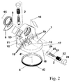
- the arrangement according to the invention consists of a supporting structure 11 of a base body 1 (only shown in FIG. 2), a drive unit 2, which consists at least of rotor 21 and stator 22, and fixing means in the form of screws 13 or Pins 14, which locks the stator 22 and possible other static additional components of the drive unit 2 against rotation due to the forces and moments generated by the rotor movement.
- the rotor 21 is connected to an output shaft 26 of the drive unit 2, on which a pinion 24 is fastened, each of which rotates a functional element 4, 5 or 6 (only shown in FIG. 2) about a fixed axis of rotation 41 or 65 of the base body 1 .
- the rotor 21 is preferably a brushless permanent magnet rotor.
- FIG. 1 With its rotor shaft, as shown in FIG. 1 as a preferred variant, it engages in an additional reducing gear 25 on the output side. For reasons of space and symmetry, this is designed as a coaxial gear. It also contains the bearing functions for both the rotor shaft and for the output shaft 26 on which the pinion 24 is seated.
- the pinion 24 is for stabilization in a pinion counter bearing 8, which is incorporated in the support structure 11 of the base body 1 in this case.
- a position sensor 28 and a brake 29 are mounted on the side of the rotor 21 opposite the output shaft 26 in the same cylindrical outer shape as the stator 22.
- the position transmitter 28 can be used for drive control, for example in the case of brushless synchronous motors, but on the other hand also serves to determine the position of the driven axes 41 or 65.
- the brake 29, whose function is normally that of a holding brake, is arranged on the rotor shaft adjacent to the position transmitter 28. In special cases, for example in the context of specific safety requirements, it may be necessary, however, that the driven payload on the axis of rotation 41 must be braked from full speed in an emergency.
- the drive counter bearing 27, which is usually present in a launching cap 23, is arranged in this example between position transmitter 28 and brake 29. For the sake of manufacturing technology, the end cap 23 in this case contains only the brake 29 and the position sensor 28 is mounted with the drive counter bearing 27 in a further cylindrical component.
- All of the components of the drive unit 2 that are now described are inserted in a cylindrical recess 12 of the supporting structure 11 of the base body 1, drawn in the axial longitudinal section, and are rigidly fastened in the supporting structure 11 to absorb the forces and moments caused by the movement of the rotor 21
- all static drive components are rigidly fastened in the support structure 11 by means of screws 13 or by means of pins 14. Ie the attachment can be non-positive and / or positive. In the case of poor accessibility, a form-fitting power transmission with long adapters is also conceivable, which are each inserted into prefabricated grooves in the walls of the cylindrical recess 12 and the individual components of the drive 2.
- the base body 1 here is an angled two-axis platform, which is designed as a support for drives for two fixed axes of rotation 41 and 65.
- a total of three functional elements 4, 5 and 6 can be moved relative to the platform (base body 1), each individual movement being a rotary movement and two of the functional elements 5 and 6 having a common axis of rotation 65.
- Each functional element 4, 5 and 6 has a toothed ring with a large diameter, of which, however, only the full toothed ring 42 is designated in FIG. 2, which is fastened to a base frame (not shown) as the functional element 4.
- the angled base body 1 the rigidity of which is increased by struts 19 with a relatively small wall thickness, is a specially produced cast part into which cylindrical recesses 12 for receiving the drive units 2 have been made directly in its supporting structure 11. The recesses 12 are made so that the drive units 2 can be inserted with a precise fit.
- the drive units 2 are secured in the support structure 11 of the base body 1 against rotation about their respective axes 15 or 18 of the cylindrical recess 12, as already described for FIG. 1.
- the output shaft 26 with the pinion 24 protrudes from the support structure 11 in order to engage in the respective ring gear of the functional element 4, 5 or 6.
- Rotor 21, gear 25 and output shaft 26 with pinion 24 of the drive unit 2 are inserted into the supporting structure 11 of the base body 1.
- the stator 22 is also in the Stator housing "in the form of the cylindrical recess 12 of the support structure 11.
- the drive unit 2 is then fixed in the support structure 11 by an end cap 23, which contains at least the rotor counter bearing 27 and optionally a position sensor 28 and a brake 29.
- the recess 12 around the axis 15 is worked directly into the full material of the base body 1, the recess 12 around the axis 18 of the second drive unit 2 shown for the functional element 6 is to a greater extent through the support structure 11 of the base body 1 in the form of a molded housing structure been integrated with struts 19.
- the pinion 24 can also be a friction wheel for small and light functional elements 4, 5 or 6 with lower accuracy requirements.
- the drive unit 2 is arranged in the cylindrical recess 12 belonging to the axis 15. Since the base body 1 is symmetrical with respect to the common axis of rotation 65 of the functional elements 5 and 6, a further drive unit 2 can be introduced into a recess 12 with the axis 16 with respect to the axis of rotation 41 of the functional element 4. As a synchronously operated drive unit 2, this can permanently improve the performance of the drive about the axis of rotation 41.
- special applications such as here for the straightening mechanism indicated in Fig.
- the drive unit 2 integrated in the support structure 11 is shown in FIG. 3 in its prefabrication stage (before insertion into the base body 1).
- the components of the drive unit 2 are the rotor 21 and the stator 22, the pinion 24 on the output shaft 26 and the inter-coupled coaxial gear 25.
- the gear 25 is not absolutely necessary as a coaxial gear, but is a preferred variant for reasons of space and integration.
- the gear 25 is therefore only shown as a unit housed in a supporting housing. Together with the end cap 23, which contains the rotor counter bearing 27, position transmitter 28 and brake 29, all components are preassembled and adjusted in a sleeve 7 for easier installation in the support structure 11.
- the sleeve 7 is only a support structure for adjusting the components and is not suitable for absorbing the engine torques.
- the assembly is therefore based on the dimensionally accurate manufacture of all components with a cylindrical outer shape, so that they practically only have to be stacked in order in the sleeve 7.
- the design of the pinion 24 and its storage allow several variants.
- the preferred variant is the floating bearing, ie the output shaft 26 is sufficiently supported within the gear 25 and the pinion is located on the free end of the output shaft. With large loads (torques), however, a second bearing point is always indicated for reasons of stability. For this purpose, a second bearing point in the form of a counter bearing 8 introduced into the supporting structure 11 of the base body 1 is already indicated in FIG. 1 and the associated description.
- the pinion 24 can be designed to improve the stationary positioning accuracy of the exemplary selected functional element 4 with respect to its engagement in the ring gear 42.
- This bracing is achieved in the simplest case in that two identically toothed partial pinions engage tightly adjacent to one another via a torsion spring braced against one another in the driven toothed ring, so that the teeth of the two partial pinions each abut on opposite tooth flanks of the driven toothed ring 42.
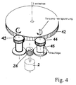
- gear element 43 consists of gear wheels rigidly fixed on one axis and serves to transmit power from the pinion 24 to the driven ring gear 42
- gear element 44 two gear wheels identically geared to gear element 43 are present in gear element 44, which can be rotated against each other on the same axis and stops for torsion have spiral spring 45 located between them.
- the torsion of the spiral spring 45 is achieved by the rotation of the upper gear wheel of the gear element 44 relative to the lower gear wheel before insertion into the ring gear 42.
- the upper gearwheel of the gear element 44 engaging in the driven ring gear 42 counteracts the direction of rotation of the driving gearwheel of the gear element 43 with a defined force. It follows that - although both gear elements 43 and 44 are set into a rotational movement in the same direction by the pinion 24 - opposing force components act on the driven ring gear 42, as the opposite rotation arrows around the axes of rotation of the gear elements 43 and 44 are intended to illustrate.
Landscapes
- Engineering & Computer Science (AREA)
- Power Engineering (AREA)
- Physics & Mathematics (AREA)
- Electromagnetism (AREA)
- Microelectronics & Electronic Packaging (AREA)
- Connection Of Motors, Electrical Generators, Mechanical Devices, And The Like (AREA)
- Jigs For Machine Tools (AREA)
Abstract
Description
Die Erfindung betrifft eine Anordnung zum Antrieb von Funktionselementen um mehrere
unabhängige Achsen und ein Verfahren zu ihrer Herstellung, insbesondere für solche
Anwendungen, bei denen Antriebe mit hohem Drehmoment und geringer Masse und
geringem Raumbedarf gefordert sind, wie z.B. Antriebe von optischen und/oder
stabilisierten Plattformen oder von mehrdimensionalen Handhabungseinrichtungen von
Robotern oder Manipulatoren.
In der elektrischen Antriebstechnik kommen normalerweise Antriebseinheiten zum Einsatz,
die aus einem Motor mit angekoppeltem Getriebe und einem Antriebsritzel bestehen. Eine
Ausnahme bilden sogenannte Direktantriebe, wobei der Rotor des Motors direkt auf der
anzutreibenden Welle montiert ist.
Aufgrund der begrenzten erzielbaren Drehmomente solcher Direktantriebe bleibt ihr
Einsatz auf sehr spezielle Anwendungen begrenzt. Bei Anwendungen, die eine schnelle,
präzise Positionierung von Bewegungselementen mit relativ großer Masse erfordern, ist ein
Einsatz von Direktantrieben mit hohem Drehmoment aus Gründen von Gewicht- und
Volumenbeschränkungen meist unmöglich. Insbesondere bei Plattformen, mit denen
Funktionselemente unabhängig in mehreren Achsen bewegt werden sollen, ist wegen der
Notwendigkeit mehrerer Antriebseinheiten deren Volumenminimierung unumgänglich, so
daß hierfür nur kleine Antriebseinheiten mit Ritzel, d.h. bestehend aus Motor und
Untersetzungsgetriebe, zum Einsatz kommen. Eine solche Anwendung ist in der
Patentschrift DE 35 16 377 für die Beaobachtungseinrichtung eines Hubschraubers
beschieben, wobei die Probleme des Antriebs jedoch nicht analysiert und gelöst worden
sind. Aufgrund der hier (in Fig. 5 und zugehöriger Beschreibung) dokumentierten üblichen
Bauweise solcher Antriebseinheiten, bei denen jede Antriebseinheit ihr eigenes Gehäuse
hat und ihre Befestigung an einer Flanschfläche des Gehäuses erfolgt, ist die Lage der
Flanschfläche bezogen auf den Masse-Schwerpunkt der Antriebseinheit sehr ungünstig.
Dies führt bei Vibrationen im mobilen Einsatz zu extrem hohen Belastungen und damit
Verformungen im Bereich des Befestigungsflansches mit solch negativen Erscheinungen,
wie z.B. wechselnde Verhältnisse im Zahneingriff des Ritzels.
Daraus ergibt sich, daß die Forderungen nach geringem Gewicht und Volumen bei
gleichzeitig hoher Leistungsfähigkeit bezüglich Drehmoment, Genauigkeit sowie
Unempfindlichkeit gegenüber Vibrationsbelastungen (z.B. durch eine hohe
Resonanzfrequenz) konträr zueinander stehen und mit den bekannten Antriebsmitteln des
Standes der Technik nicht zu lösen sind.The invention relates to an arrangement for driving functional elements around several independent axes and a method for their production, in particular for those applications in which drives with high torque and low mass and small space requirements are required, such as drives of optical and / or stabilized platforms or of multi-dimensional handling devices of robots or manipulators.
In electrical drive technology, drive units are usually used, which consist of a motor with a coupled gear and a drive pinion. An exception are so-called direct drives, where the rotor of the motor is mounted directly on the shaft to be driven.
Due to the limited achievable torques of such direct drives, their use remains limited to very special applications. In applications that require fast, precise positioning of moving elements with a relatively large mass, the use of direct drives with high torque is mostly impossible due to weight and volume restrictions. In particular on platforms with which functional elements are to be moved independently in several axes, their volume minimization is unavoidable because of the need for several drive units, so that only small drive units with pinion, ie consisting of motor and reduction gear, are used for this. Such an application is described in the patent specification DE 35 16 377 for the observation device of a helicopter, although the problems of the drive have not been analyzed and solved. Due to the usual design of such drive units, documented here (in FIG. 5 and associated description), in which each drive unit has its own housing and is fastened to a flange surface of the housing, the position of the flange surface in relation to the center of mass of the drive unit is very high unfavorable. With vibrations in mobile use, this leads to extremely high loads and thus deformations in the area of the mounting flange with such negative phenomena, such as, for example, changing conditions in the tooth engagement of the pinion.
It follows from this that the demands for low weight and volume combined with high performance in terms of torque, accuracy and insensitivity to vibration loads (for example due to a high resonance frequency) are contrary to one another and cannot be solved with the known drive means of the prior art.
Der Erfindung liegt die Aufgabe zugrunde, eine neue Möglichkeit zum Antrieb von Funktionselementen um mehrere unabhängige Achsen zu finden, die bei geringer Masse und geringem Raumbedarf ein hohes Drehmoment, eine große Genauigkeit in der Positionierung und Stabilisierung des Bewegungselements in der jeweiligen Achse gewährleistet.The invention has for its object a new way to drive Functional elements to find several independent axes, with low mass and low space requirements high torque, great accuracy in the Positioning and stabilizing the movement element in the respective axis guaranteed.
Erfindungsgemäß wird die Aufgabe bei einer Anordnung zum Antrieb von
Funktionselementen um mehrere unabhängige Achsen, bei der zur Ausrichtung der
Funktionselemente für jede Drehachse mindestens eine Antriebseinheit vorhanden ist und
als Träger der Funktionselemente sowie der Antriebseinheiten ein Grundkörper vorgesehen
ist, dadurch gelöst, daß die Antriebseinheit bezüglich der Stütz- und Stabilisierungsfunktion
des Stators vollständig im Material und in der tragenden Struktur des Grundkörpers
integriert ist, wobei der Grundkörper im wesentlichen zylindrische Ausnehmungen zur
Aufnahme aller Komponenten der Antriebseinheit aufweist und Mittel zur starren Fixierung
mindestens gegenüber tangentialen Kräften und Momenten des Stators, die der
Drehbewegung des Rotors der Antriebseinheit entgegenwirken, in der Tragstruktur des
Grundkörpers vorgesehen sind.
Die Fixierung der Antriebseinheit in der Tragstruktur des Grundkörpers wird zweckmäßig
formschlüssig ausgeführt. Dazu eignet sich der Einsatz von Paßstücken, wobei die
Paßstücke in Nuten, die die Antriebseinheit und die zylindrische Ausnehmung in
Längsrichtung der zylindrischen Ausnehmung des Grundkörpers aufweisen, angeordnet
sind. In einer anderen vorteilhaften Variante wird die Antriebseinheit durch Stifte in der
Tragstruktur des Grundkörpers gegen Verdrehung und zusätzlich gegen axiale
Verschiebung gesichert.
Die Antriebseinheit wird in einer weiteren Ausgestaltung kraftschlüssig in der Tragstruktur
des Grundkörpers fixiert. Dabei ist die Antriebseinheit vorzugsweise mittels Schrauben in
der Tragstruktur des Grundkörpers fixiert. Es ergeben sich dieselben Vorteile wie bei der
Verwendung von Stiften, jedoch wird zusätzlich ein besser Wärmekontakt zwischen der
Antriebseinheit und der umgebenden Tragstuktur hergestellt.
Die Antriebseinheit ist vorteilhaft mit einem Getriebe versehen, das die Drehbewegung auf
das jeweilige Funktionselement überträgt, um eine Drehzahlreduktion des
Funktionselements zu erzielen. Dabei ist von Vorteil, wenn das Getriebe teilweise in der
Struktur des Grundkörpers integriert ist, wobei die Antriebseinheit eine Abtriebswelle mit
Ritzel aufweist und für jedes der Funktionselemente ein Zahnkranz mit großem Radius zur
Übertragung der Drehbewegung vom Ritzel auf das Funktionselement vorhanden ist und
im Grundkörper gelagert bzw. geführt wird.
Für bestimmte Anwendungen kann es erforderlich sein, daß die Antriebseinheit vor der mit
dem Ritzel versehenen Abtriebswelle ein zusätzliches Getriebe enthält. Dieses ist
zweckmäßig ein koaxiales Getriebe, wodurch die Kompaktheit und Symmetrie der
gesamten Antriebseinheit erhalten bleibt.
Bei Einbringung der Antriebseinheit in die Tragstruktur des Grundkörpers gibt es
verschiedene Möglichkeiten, das Ritzel, das den (großen) Zahnkranz des Funktionselements
antreibt, zu lagern. In einer ersten Variante ist das Ritzel fliegend gelagert. Eine stabilere
und damit für viele Anwendungen zweckmäßigere Möglichkeit besteht darin, das Ritzel
beidseitig zu lagern. Während das Ritzel einerseits entweder mit einem Lager der
Motorwelle oder der Lagerung der Abtriebswelle des zusätzlichen Getriebes der
Antriebseinheit gelagert ist gibt es für das Gegenlager des Ritzels
Gestaltungsmöglichkeiten, die sich in ihrem Fertigungsaufwand und der erreichbaren
Stabilität unterscheiden. Zum einen ist es der Stabilitätsforderung des Ritzeleingriffs in den
angetriebenen Zahnkranz zuträglich, wenn das Ritzel in der Tragstruktur des Grundkörpers
integriert ist. Zum anderen sind die Anforderungen an Justierung und Fertigung wesentlich
geringer, wenn das Gegenlager des Ritzels in einer mit der Antriebseinheit verbundenen
Hilfsstruktur montiert ist.
In diesem Fall ist die Hilfsstruktur vorteihaft am Gehäuse des des zusätzlichen Getriebes
angebracht ist.
Für eine spielfreie Kraftübertragung vom Ritzel auf den (großen) Zahnkranz des
Funktionselements ist vorteilhaft eine mechanisch verspannte Ritzelanordnung einzusetzen.
Die mechanisch verspannte Ritzelanordnung besteht vorzugsweise aus zwei Teilritzeln mit
gleicher Verzahnung, wobei ein Teilritzel starr und das andere drehbar eng benachbart auf
der Abtriebswelle der Antriebseinheit befestigt sind und ein zwischen den Teilritzeln
befindliches Federelement (Torsionsfeder, Zugfeder oder Druckelement) durch Verdrehen
des drehbaren Teilritzels gespannt arretiert ist, wenn beide Teilritzel in den (großen)
Zahnkranz des Funktionselements eingreifen.
In einer anderen Ausführung weist die mechanisch verspannte Ritzelanordnung ein
gewöhnliches Ritzel auf der Abtriebswelle der Antriebseinheit und zwei zusätzliche
Getriebeelemente mit identischer Verzahnung und jeweils zwei Zahnrädern auf, über die
das Ritzel der Abtriebswelle den großen Zahnkranz antreibt, wobei die beiden Zahnräder
des einen Getriebeelementes starr verbunden und die des anderen auf einer Achse mittels
Torsion einer Feder gekoppelt sind. Beide Ritzelanordnungen gewährleisten, daß die
treibenden Zahnräder am getriebenen Zahnkranz unterschiedliche Zahnflanken
beanspruchen und somit praktisch ein spielfreier Zahnradantrieb vorliegt.
Es erweist sich als vorteilhaft, wenn die Antriebseinheit mit verschiedenen zusätzlichen
Komponenten in einer Stützkonstruktion montiert ist, wobei die Stützkonstruktion zur
Justierung der Komponenten zueinander und nicht zur Aufnahme der durch die
Rotorbewegung auf den Stator ausgeübten Kräfte und Momente vorgesehen ist.
Als Stützkonstruktion eignet sich vorzugsweise eine zylindrische Hülse.
Die Antriebseinheit kann vorteilhaft als zusätzliche Komponenten eine Bremse und/oder
einen Positionsgeber zur Antriebssteuerung und Positionsbestimmung des angetriebenen
Funktionselements enthalten. Für bestimmte Anwendungen ist es vorteilhaft oder sogar
erforderlich, bei Ausfall der Antriebseinheit einen Notantrieb vorzusehen.
Dieser ist im einfachsten Fall ein Anschluß für einen Handantrieb am rückwärtigen Ende der
Antriebseinheit. Ist das rückwärtige Ende der Antriebseinheit schwer zugänglich oder aus
einem anderen Grund für einen Handantrieb nicht geeignet, wird vorzugsweise ein
elektrischer Notantrieb eingesetzt. Dieser kann in besonderen Fällen auch eine völlig
selbständige Antriebseinheit der erfindungsgemäßen Art sein und sogar als redundante
Antriebseinheit in denselben angetriebenen Zahnkranz des zu bewegenden
Funktionselements eingreifen.According to the invention, the object is achieved in an arrangement for driving functional elements around a plurality of independent axes, in which at least one drive unit is provided for aligning the functional elements for each axis of rotation and a base body is provided as a carrier for the functional elements and the drive units, in that the drive unit with respect to the support and stabilization function of the stator is fully integrated in the material and in the supporting structure of the base body, the base body having essentially cylindrical recesses for receiving all components of the drive unit and means for rigid fixation at least with respect to tangential forces and moments of the stator Counteracting the rotary movement of the rotor of the drive unit are provided in the support structure of the base body.
The fixation of the drive unit in the supporting structure of the base body is advantageously carried out in a form-fitting manner. The use of adapters is suitable for this purpose, the adapters being arranged in grooves which the drive unit and the cylindrical recess have in the longitudinal direction of the cylindrical recess of the base body. In another advantageous variant, the drive unit is secured against rotation and additionally against axial displacement by pins in the supporting structure of the base body.
In a further embodiment, the drive unit is non-positively fixed in the supporting structure of the base body. The drive unit is preferably fixed in the supporting structure of the base body by means of screws. The advantages are the same as when using pins, but in addition a better thermal contact between the drive unit and the surrounding supporting structure is produced.
The drive unit is advantageously provided with a gear that transmits the rotary movement to the respective functional element in order to achieve a speed reduction of the functional element. It is advantageous if the gearbox is partially integrated in the structure of the base body, the drive unit having an output shaft with pinion and for each of the functional elements there is a ring gear with a large radius for transmitting the rotary movement from the pinion to the functional element and stored in the base body or is led.
For certain applications it may be necessary that the drive unit contains an additional gear in front of the output shaft provided with the pinion. This is expediently a coaxial transmission, whereby the compactness and symmetry of the entire drive unit is retained.
When the drive unit is inserted into the supporting structure of the base body, there are various options for mounting the pinion that drives the (large) ring gear of the functional element. In a first variant, the pinion is overhung. A more stable and therefore more suitable option for many applications is to mount the pinion on both sides. While the pinion is supported either with a bearing of the motor shaft or the bearing of the output shaft of the additional gear of the drive unit, there are design options for the counter bearing of the pinion, which differ in terms of their production costs and the stability that can be achieved. On the one hand, it is conducive to the stability requirement of the pinion engagement in the driven ring gear if the pinion is integrated in the supporting structure of the base body. On the other hand, the requirements for adjustment and production are significantly lower if the pinion counter bearing is mounted in an auxiliary structure connected to the drive unit.
In this case, the auxiliary structure is advantageously attached to the housing of the additional gear.
A mechanically clamped pinion arrangement is advantageously used for a play-free power transmission from the pinion to the (large) ring gear of the functional element. The mechanically clamped pinion arrangement preferably consists of two partial pinions with the same toothing, one partial pinion rigid and the other rotatably fastened in close proximity to the output shaft of the drive unit, and a spring element (torsion spring, tension spring or pressure element) located between the partial pinions is tensioned by rotating the rotatable partial pinion is locked when both pinions engage in the (large) ring gear of the functional element.
In another embodiment, the mechanically clamped pinion arrangement has a conventional pinion on the output shaft of the drive unit and two additional gear elements with identical teeth and two gears each, via which the pinion of the output shaft drives the large ring gear, the two gears of one gear element being rigidly connected and that of the other are coupled on one axis by means of torsion of a spring. Both pinion arrangements ensure that the driving gears on the driven ring gear take up different tooth flanks and thus there is practically a backlash-free gear drive.
It proves to be advantageous if the drive unit with various additional components is mounted in a support structure, the support structure being provided for adjusting the components to one another and not for absorbing the forces and moments exerted on the stator by the rotor movement.
A cylindrical sleeve is preferably suitable as a support structure.
The drive unit can advantageously contain a brake and / or a position transmitter for drive control and position determination of the driven functional element as additional components. For certain applications, it is advantageous or even necessary to provide an emergency drive if the drive unit fails.
In the simplest case, this is a connection for a manual drive at the rear end of the drive unit. If the rear end of the drive unit is difficult to access or is not suitable for a manual drive for another reason, an electric emergency drive is preferably used. In special cases, this can also be a completely independent drive unit of the type according to the invention and can even intervene as a redundant drive unit in the same driven ring gear of the functional element to be moved.
Die Aufgabe wird erfindungsgemäß mit einem Verfahren zur Herstellung von strukturintegrierten Antriebseinheiten, dadurch gelöst, daß die notwendigen und ergänzenden Elemente der Antriebseinheit in Form von aufeinander abgestimmten im wesentlichen zylindrischen Komponenten mit einheitlichem Durchmesser gefertigt werden, die Komponenten der Antriebseinheit in eine bezüglich Form und Größe angepaßte umhüllende Stützkonstruktion eingesetzt und in dieser zueinander justiert werden, wobei die Stützkonstruktion nicht zur Aufnahme der durch die Rotorbewegung auf den Stator ausgeübten Kräfte und Momente geeignet ist, die Stützkonstruktion mit den justierten Komponenten der Antriebseinheit in eine passend vorgefertigte, im wesentlichen zylindrische Ausnehmung im Material der tragenden Struktur eines Grundkörpers eingesetzt wird und die Komponenten der Antriebseinheit durch die Stützkonstuktion hindurch im Material der tragenden Struktur des Grundkörpers gegen Verdrehen um die Achse der Antriebseinheit gesichert werden.The object is achieved with a method for producing Structure-integrated drive units, solved in that the necessary and complementary elements of the drive unit in the form of coordinated in essential cylindrical components are manufactured with a uniform diameter, the components of the drive unit in a form and size adapted enveloping support structure used and adjusted to each other in this, wherein the support structure does not accommodate the stator caused by the rotor movement exerted forces and moments is suitable, the support structure with the adjusted Components of the drive unit into a suitably prefabricated, essentially cylindrical recess in the material of the supporting structure of a base body is used and the components of the drive unit through the support structure through in the material of the supporting structure of the base body against twisting around the Axis of the drive unit are secured.
Die Grundidee der Erfindung basiert auf der Überlegung, daß bei kleinen und leichten
Kompaktantrieben, die an einem Grundkörper die Bewegung von Funktionselementen
realisieren, große Drehmomente in der Regel zu Verformungen der Flanschelemente des
Antriebs führen, in deren Folge Störungen der Wärmeableitung und der Getriebeeingriffe
entstehen. Diese Probleme werden nahezu vollständig mittels einer lastsymmetrischen
Antriebshalterung innerhalb der tragenden Struktur des Grundkörpers beseitigt Dazu sieht
eine vorzuziehende Ausgestaltung der Erfindung vor, die Komponenten der Antriebseinheit
in einer leichten Stützkonstruktion vorzumontieren und zu justieren, bevor sie als gesamtes
Antriebspaket in die passende Ausnehmung der Tragstruktur des Grundkörpers eingesetzt
wird und alle nicht rotierenden Komponenten der Antriebseinheit starr, mindestens gegen
Verdrehen um die Abtriebswelle, in der Tragstruktur befestigt werden.
Die Erfindung ermöglicht somit die Realisierung von Antrieben für Funktionselemente um
mehrere unabhängige Achsen ortsfest zu einem Grundkörper, die bei geringer Masse und
geringem Raumbedarf ein hohes Drehmoment, eine große Genauigkeit in der
Positionierung und Stabilisierung des Bewegungselements in der jeweiligen Achse
gewährleisten. Weiterhin werden einfache Fertigung und Justierung solcher Antriebe
ermöglicht.The basic idea of the invention is based on the consideration that, in the case of small and light compact drives which implement the movement of functional elements on a base body, large torques generally lead to deformations of the flange elements of the drive, as a result of which heat dissipation and gearbox interferences occur. These problems are almost completely eliminated by means of a load-symmetrical drive bracket within the supporting structure of the base body.For this purpose, a preferred embodiment of the invention provides for the components of the drive unit to be pre-assembled and adjusted in a light support structure before they fit as a complete drive package into the matching recess in the supporting structure of the Base body is used and all non-rotating components of the drive unit are fixed rigidly, at least against rotation around the output shaft, in the support structure.
The invention thus enables drives for functional elements to be fixed about a plurality of independent axes to form a base body, which, with low mass and small space requirements, ensure high torque, great accuracy in the positioning and stabilization of the movement element in the respective axis. Furthermore, simple manufacture and adjustment of such drives are made possible.
Die Erfindung soll nachstehend anhand von Ausführungsbeispielen näher erläutert werden.
Die Zeichnungen zeigen:
- Fig. 1:
- den Prinzipaufbau einer erfindungsgemäßen Antriebseinheit,
- Fig. 2:
- eine mögliche Variante zur Einbringung von erfindungsgemäßen Antriebseinheiten in die Tragstruktur einer zweiachsigen Plattform (Grundkörper),
- Fig. 3:
- eine Ausführungsform der erfindungsgemäßen Antriebseinheit in einer Stützstruktur zur Vormontagen und Justierung der Antriebskomponenten, und
- Fig. 4:
- eine Variante zur Realiserung einer verspannten Ritzelanordnung.
The drawings show:
- Fig. 1:
- the basic structure of a drive unit according to the invention,
- Fig. 2:
- a possible variant for the introduction of drive units according to the invention into the supporting structure of a two-axis platform (base body),
- Fig. 3:
- an embodiment of the drive unit according to the invention in a support structure for preassembly and adjustment of the drive components, and
- Fig. 4:
- a variant for realizing a tensioned pinion arrangement.
Die erfindungsgemäße Anordnung besteht -wie aus Fig. 1 entnehmbar - aus einer
tragenden Struktur 11 eines Grundkörpers 1 (nur in Fig. 2 dargestellt), einer Antriebseinheit
2, die zumindest aus Rotor 21 und Stator 22 besteht und Fixierungsmitteln in Form von
Schrauben 13 oder Stiften 14, die den Stator 22 und mögliche andere statische
Ergänzungskomponenten der Antriebseinheit 2 gegen Verdrehen infolge der durch die
Rotorbewegung erzeugten Kräfte und Momente arretiert. Der Rotor 21 steht mit einer
Abtriebswelle 26 der Antriebseinheit 2 in Verbindung, auf der ein Ritzel 24 befestigt ist, das
jeweils ein Funktionselement 4, 5 oder 6 (nur in Fig. 2 dargestellt) um eine körperfeste
Drehachse 41 oder 65 des Grundkörpers 1 dreht.
Der Rotor 21 ist vorzugsweise ein bürstenlos angetriebener Permanentmagnetläufer. Er
greift mit seiner Rotorwelle, wie in Fig. 1 als bevorzugte Variante dargestellt, abtriebsseitig
in ein zusätzliches untersetzendes Getriebe 25 ein. Aus Platz- und Symmetriegründen ist
diese als koaxiales Getriebe ausgebildet. Es enthält zugleich die Lagerfunktionen sowohl für
die Rotorwelle als auch für die Abtriebswelle 26, auf der das Ritzel 24 sitzt. Das Ritzel 24 ist
zur Stabilisierung in einem Ritzelgegenlager 8, das in diesem Fall in der Tragstruktur 11 des
Grundkörpers 1 eingearbeitet ist.
Auf der der Abtriebswelle 26 entgegengesetzten Seite des Rotors 21 sind in derselben
zylindrischen Außenform wie der Stator 22 ein Positionsgeber 28 und eine Bremse 29
angebracht. Der Positionsgeber 28 kann für die Antriebssteuerung, z.B. bei bürstenlosen
Synchronmotoren, benutzt werden, dient andererseits aber auch zur Positionsermittlung
der angetriebenen Achsen 41 oder 65.
Benachbart zum Positionsgeber 28 ist auf der Rotorwelle die Bremse 29 angeordnet, deren
Funktion im Normalfall die einer Haltebremse ist. In besonderen Fällen, z.B. im Rahmen von
spezifischen Sicherheitsforderungen, kann es jedoch notwendig sein, daß die angetriebene
Nutzlast auf der Drehachse 41 im Notfall aus voller Geschwindigkeit heraus abgebremst
werden muß. Das üblicherweise in einer Abschußkappe 23 vorhandene Antriebsgegenlager
27 ist in diesem Beispiel zwischen Positionsgeber 28 und Bremse 29 angeordnet. Aus
fertigungstechnischer Zweckmäßigkeit enthält die Abschlußkappe 23 in diesem Fall
lediglich die Bremse 29 und der Positionsgeber 28 ist mit dem Antriebsgegenlager 27 in
einem weiteren zylindrischen Bauteil montiert. Alle nunmehr beschriebenen Komponenten
der Antriebseinheit 2 sind in einer im Achslängsschnitt gezeichneten zylindrischen
Ausnehmung 12 der Tragstruktur 11 des Grundkörpers 1 eingesetzt und werden zur
Aufnahme der durch die Bewegung des Rotors 21 verursachten Kräfte und Momente in
der Tragstruktur 11 starr befestigt In dem in Fig. 1 dargestellten Beispiel sind alle statischen
Antriebskomponenten in der Tragstruktur 11 mittels Schrauben 13 oder mittels Stiften 14
starr befestigt. D.h. die Befestigung kann kraft- und/oder formschlüssig sein. Bei schlechter
Zugänglichkeit ist auch eine formschlüssige Kraftübertragung mit langen Paßstücken
denkbar, die in den Wandungen der zylindrischer Ausnehmung 12 und den einzelnen
Komponenten des Antriebs 2 jeweils in vorgefertigte Nuten eingesetzt werden. Da die
formschlüssige Befestigung in der zylindrischen Ausnehmung 12 in erster Linie die
Komponenten der Antriebseinheit 2 gegen Verdrehen sichern soll, sind die Nuten und
damit die Paßstücke entlang der Mantellinie der zylindrischen Ausnehmung 12
auszurichten. Es sind ebenso auch Verzahnungen der Antriebskomponenten mit der
zylindrischen Ausnehmung 12 entlang der gesamten Zylinderwandung als wirksame
formschlüssige Sicherung gegen Verdrehen einsetzbar.
In Fig. 2 ist eine Anwendung der erfindungsgemäßen Antriebe in einer Explosivdarstellung
gezeigt, bei der hohe Anforderungen an die Dynamik, die Steifigkeit und die Genauigkeit
der Ausrichtung gestellt werden. Der Grundkörper 1 ist hier eine gewinkelte zweiachsige
Plattform, die als Träger von Antrieben für zwei körperfeste Drehachsen 41 und 65
ausgebildet ist. Gegenüber der Plattform (Grundkörper 1) sind insgesamt drei
Funktionselemente 4, 5 und 6 zu bewegen, wobei jede Einzelbewegung eine
Drehbewegung ist und zwei der Funktionselemente 5 und 6 eine gemeinsame Drehachse
65 aufweisen. Jedes Funktionselement 4, 5 und 6 weist einen Zahnkranz mit großem
Durchmesser auf, von denen in Fig. 2 jedoch nur der volle Zahnkranz 42 bezeichnet ist, der
an einem Basisgestell (nicht darstellt) als Funktionselement 4 befestigt ist.
Der gewinkelte Grundkörper 1, dessen Steifigkeit bei relativ geringer Wandstärke durch
Streben 19 erhöht wird, ist ein speziell gefertigtes Gußteil, in das zylindrische
Ausnehmungen 12 zur Aufnahme der Antriebseinheiten 2 direkt in dessen tragende
Struktur 11 eingebracht wurden. Die Ausnehmungen 12 sind so eingebracht, daß die
Antriebseinheiten 2 paßgenau eingeschoben werden können. Die Antriebseinheiten 2
werden in der Tragstruktur 11 des Grundkörpers 1 um ihre jeweilige Achse 15 oder 18 der
zylindrischen Ausnehmung 12, wie bereits zu Fig. 1 beschrieben, gegen Verdrehen
gesichert. Dabei ragt die Abtriebsachse 26 mit dem Ritzel 24 aus der Tragstruktur 11
heraus, um in den jeweiligen Zahnkranz des Funktionselements 4, 5 oder 6 einzugreifen.
Rotor 21, Getriebe 25 und Abtriebswelle 26 mit Ritzel 24 der Antriebseinheit 2 werden in
die tragende Struktur 11 des Grundkörpers 1 eingeschoben. Der Stator 22 wird ebenfalls in
das ![]()
The
A
The
2 shows an application of the drives according to the invention in an exploded view, in which high demands are placed on the dynamics, the rigidity and the accuracy of the alignment. The
The
![]()
Während die Ausnehmung 12 um die Achse 15 direkt ins volle Material des Grundkörpers
1 eingearbeitet ist, ist die Ausnehmung 12 um die Achse 18 der zweiten dargestellten
Antriebseinheit 2 für das Funktionselement 6 in größerem Maße durch die Tragstruktur 11
des Grundkörpers 1 in Form einer abgeformten Gehäusestruktur mit Streben 19 integriert
worden. Beide ziemlich verschiedenen Einbettungen in die Tragstruktur 11 des
Grundkörpers 1 erfüllen jedoch neben der Gewicht- und Volumenminimierung der
Antriebe vor allem die symmetrische Lastverteilung am strukturintegrierten
Bei Anwendungen mit sehr hoher Drehgeschwindigkeit der anzutreibenden Drehachse 41
oder 65 des Funktionselements 4, 5 oder 6 kann es sinnvoll sein, das Ritzel 24 direkt auf
die Rotorwelle aufzusetzen, so daß das Getriebe 25 entfällt. Dabei kann auch die
Verzahnung direkt auf der Rotorwelle aufgebracht sein, so daß es kein separates Ritzel 24
aufgesetzt ist. Ausnahmsweise kann das Ritzel 24 für kleine und leichte Funktionselemente
4, 5 oder 6 mit geringeren Genauigkeitsanforderungen auch ein Reibrad sein.
Für das Funktionselement 4, das in Fig. 2 ein Basisgestell für den als stabisierte Plattform
ausgebildeten Grundkörper 1 ist, wird die Antriebseinheit 2 in der zur Achse 15 gehörige
zylindrische Ausnehmung 12 angeordnet. Da der Grundkörper 1 symmetrisch gegenüber
der gemeinsamen Drehachse 65 der Funktionselemente 5 und 6 ist, läßt sich bezüglich der
Drehachse 41 des Funktionselements 4 in eine Ausnehmung 12 mit der Achse 16 eine
weitere Antriebseinheit 2 einbringen. Diese kann als synchron betriebene Antriebeinheit 2
die Leistungsfähigkeit des Antriebs um die Drehachse 41 permanent verbessern.
Für spezielle Anwendungen, wie hier für die in Fig. 2 angedeutete Richtmechanik, kann es
aus Gründen der Lastverteilung oder der stationären Positioniergenauigkeit erforderlich
sein, daß das angetriebene Funktionselement 4, 5 oder 6 bei Ausfall einer Antriebseinheit 2
in eine bestimmte Position (Anfangs- oder Normalposition) zurückbewegt werden muß.
Hierfür ist am rückwärtigen Ende 9 der Rotorwelle der Antriebseinheit 2 (Fig.1) im
einfachsten Fall eine Vorkehrung für einen Handantrieb (nicht darestellt) vorzusehen. Ist
die Antriebseinheit 2 anwendungsbedingt nicht zugänglich, ergibt sich die Möglichkeit, an
gleicher Stelle einen elektrischen Notantrieb vorzusehen. Dieser elektrische Notantrieb kann
aber auch vollkommen redundant zum eigentlichen Antrieb ausgeführt sein, wenn er in
Fig. 2 in die zylindrische Ausnehmung mit der Zylinderachse 16 eingesetzt wird. Er kann
dann entweder ein echter Notantrieb sein, der im Normalbetrieb tot mitläuft, oder - wie
bereit oben beschrieben - als zusätzliche Antriebsunterstützung ständig synchron zur
Antriebseinheit 2 in der Ausnehmung 12 um die Zylinderachser 15 betrieben werden.While the
In applications with a very high rotational speed of the
For the
For special applications, such as here for the straightening mechanism indicated in Fig. 2, it may be necessary for reasons of load distribution or stationary positioning that the driven
Die in die Tragstruktur 11 integrierte Antriebseinheit 2 ist in Fig. 3 in ihrem
Vorfertigungsstadium (vor dem Einsetzen in den Grundkörper 1) dargestellt. Die
Komponenten der Antriebseinheit 2 sind der Rotor 21 und der Stator 22, das Ritzel 24 auf
der Abtriebswelle 26 und das zwischengekoppelte koaxiale Getriebe 25. Das Getriebe 25
ist nicht unbedingt als koaxiales Getriebe erforderlich, jedoch aus Platz- und
Integrationsgründen eine bevorzugte Variante. Das Getriebe 25 ist deshalb jeweils nur als in
einem tragenden Gehäuse untergebrachte Einheit gezeichnet.
Zusammen mit der Abschlußkappe 23, die Rotorgegenlager 27, Positionsgeber 28 und
Bremse 29 enthält, werden alle Komponenten zum leichteren Einbau in die Tragstruktur 11
in einer Hülse 7 vormontiert und justiert. Die Hülse 7 ist dabei nur Stützkonstruktion zur
Justierung der Komponenten und nicht geeignet, die Motordrehmomente aufzunehmen.
Die Montage basiert also auf der maßhaltigen Fertigung aller Komponenten mit
zylindrischer Außenform, so daß sie praktisch in der Hülse 7 nur der Reihe nach
eingestapelt werden müssen.
Die Ausführung des Ritzels 24 und seine Lagerung erlauben mehrere Varianten. Die
bevorzugte Variante ist die fliegende Lagerung, d.h. die Abtriebswelle 26 ist innerhalb des
Getriebes 25 ausreichend gelagert und das Ritzel befindet sich auf dem freien Ende der
Abtriebswelle. Bei großen Belastungen (Drehmomenten) ist jedoch eine zweite Lagerstelle
aus Stabilitätsgründen immer angezeigt. Dazu ist bereit in Fig.1 und der zugehörigen
Beschreibung eine zweite Lagerstelle in Form eines in die Tragstruktur 11 des Grundkörpers
1 eingebrachten Gegenlagers 8 angegeben. Diese Konstruktion erfordert hohe Präzision in
der Fertigung der Antriebseinheit 2 und der Tragstruktur 11 und ist deshalb bei
wechselndem Zukauf von Antriebseinheiten (z.B. wegen unterschiedlicher
Antriebsanforderungen) nicht immer einzuhalten.
In Fig. 3 ist nunmehr eine weitere sinnvolle konstruktive Lösung für eine zusätzliche
Lagerung der Abtriebswelle 26 dargestellt. Hier wird das Gegenlager 8 einfach mit der
vorgefertigten Antriebseinheit 2 realisiert, indem eine Haltestruktur 81 das Gegenlager 8
mit dem Getriebe 25 verbindet.The
Together with the
The design of the
In Fig. 3, another useful constructive solution for an additional bearing of the
Das Ritzel 24 kann zur Verbesserung der stationären Positioniergenauigkeit des beispielhaft
ausgewählten Funktionselements 4 bezüglich seines Eingriffs in den Zahnkranz 42
verspannt ausgeführt werden.
Diese Verspannung wird im einfachsten Fall dadurch erreicht, daß zwei identisch verzahnte
Teilritzel eng benachbart über eine Torsionsfeder gegeneinander verspannt in den
angetriebenen Zahnkranz eingreifen, so daß die Zähne der beiden Teilritzel jeweils an
entgegengesetzten Zahnflanken des angetriebenen Zahnkranzes 42 anliegen. Dadurch
ergibt sich eine spielfreie Kraftübertragung und somit eine hochgenaue Positionierung
und/oder Stabilisierung der Bewegung des Funktionselements 4 (hier: Plattform oder
beliebige andere Gerätekomponente) in der betreffenden Drehachse 41.
Fig. 4 zeigt für denselben Zweck eine ähnliche, aber aufwendigere Möglichkeit zur
Erzielung einer mechanischen Verspannung des Ritzels 24 gegenüber dem angetriebenen
Zahnkranz 42, die ebenfalls auf der Grundlage einer Torsionsverspannung beruht. Hierbei
greift das von der Antriebseinheit 2 getriebene Ritzel 24 über zwei bezüglich ihrer
Verzahnung gleichartige Getriebeelemente 43 und 44 in den angetriebenen Zahnkranz 42
ein. Während das Getriebeelement 43 aus auf einer Achse starr befestigten Zahnrädern
besteht und der Kraftübertragung vom Ritzel 24 auf den angetriebenen Zahnkranz 42
dient, sind im Getriebeelement 44 zwei identisch zum Getriebeelement 43 verzahnte
Zahnräder vorhanden, die auf derselben Achse gegeneinander drehbar sind und Anschläge
zur Torsion einer zwischen ihnen befindlichen Spiralfeder 45 aufweisen. Durch die Drehung
des oberen Zahnrades des Getriebeelements 44 gegenüber dem unteren Zahnrad wird vor
dem Einsetzen in den Zahnkranz 42 eine Torsion der Spiralfeder 45 erzielt. Dadurch wirkt
das in den angetriebenen Zahnkranz 42 eingreifende obere Zahnrad des Getriebeelements
44 der Drehrichtung des treibenden Zahnrades des Getriebeelements 43 mit einer
definierten Kraft entgegen. Daraus ergibt sich, daß - obwohl beide Getriebeelemente 43
und 44 durch das Ritzel 24 in eine gleichsinnige Rotationsbewegung versetzt werden -
gegenläufige Kraftkomponenten auf den angetriebenen Zahnkranz 42 wirken, wie die
gegenläufigen Rotationspfeile um die Rotationsachsen der Getriebeelemente 43 und 44
verdeutlichen sollen.The
This bracing is achieved in the simplest case in that two identically toothed partial pinions engage tightly adjacent to one another via a torsion spring braced against one another in the driven toothed ring, so that the teeth of the two partial pinions each abut on opposite tooth flanks of the driven
4 shows for the same purpose a similar, but more complex, way of achieving mechanical tensioning of the
Die wesentlichen Vorteile der erfindungsgemäßen Anordnung zum Antrieb von Funktionselementen um mehrere unabhängige Achsen sollen abschließend nochmals zusammenfaßt werden. Sie bestehen in einer
- Verbesserung der Kompaktheit und Struktursteifigkeit des antriebstragenden
Grundkörpers 1, da die
Antriebseinheit 2 nur den notwendigen Raum in der innerhalb Tragstruktur 11 und im wesentlichen auch innerhalb des Materials desGrundkörpers 1 einnimmt und die umgebende Struktur damit alle auftretenden Antriebsmomente symmetrisch zur Antriebsachse aufnimmt, - Verringerung des Gesamtgewichts aus Tragstruktur 11 und Antriebseinheit 2,
- Verbesserung des Vibrationsverhaltens der Antriebseinheit 2, da sie großflächig in
die Tragstruktur 11 integriert ist und eine höhere Resonanzfrequenz erhält, und - Verbesserung der Wärmeabfuhr durch direkte Ankopplung des Stators 22 an
die Tragstruktur 11, dadurch Vermeidung von Wärmenestern, wie sie bei konventioneller Motoranordnung zwischen Motorgehäuse und Tragstruktur entstehen,
- Improving the compactness and structural rigidity of the drive-carrying
base body 1, since thedrive unit 2 only takes up the necessary space in the inside of thesupport structure 11 and essentially also within the material of thebase body 1 and the surrounding structure thus absorbs all drive torques occurring symmetrically to the drive axis, - Reduction in the total weight of the
support structure 11 and driveunit 2, - Improvement of the vibration behavior of the
drive unit 2, since it is integrated over a large area in thesupport structure 11 and receives a higher resonance frequency, and - Improvement of the heat dissipation through direct coupling of the
stator 22 to thesupport structure 11, thereby avoiding heat pockets, as arise between the motor housing and the support structure in a conventional motor arrangement,
- 11
- GrundkörperBasic body
- 1111
- TragstrukturSupport structure
- 1212th
- (zylindrische) Ausnehmung(cylindrical) recess
- 1313
- SchraubenScrews
- 1414
- Stiftepencils
- 15, 16, 17, 1815, 16, 17, 18
- Achsenaxes
- 1919th
- StrebenStrive
- 22nd
- AntriebseinheitDrive unit
- 2121
- Rotorrotor
- 2222
- Statorstator
- 2323
- AbschlußkappeEnd cap
- 2424th
- Ritzelpinion
- 2525th
- Getriebetransmission
- 2626
- AbtriebsachseOutput axis
- 2727
- RotorgegenlagerRotor counter bearing
- 2828
- PositionsgeberPosition transmitter
- 2929
- Bremsebrake
- 44th
- FunktionselementFunctional element
- 4141
- DrehachseAxis of rotation
- 4242
- ZahnkranzSprocket
- 43, 4443, 44
- GetriebeelementeGear elements
- 4545
- SpiralfederCoil spring
- 5, 65, 6
- FunktionselementeFunctional elements
- 77
- HülseSleeve
- 88th
- RitzelgegenlagerPinion counter bearing
- 99
- rückwärtiges Ende der Rotorwellerear end of the rotor shaft
Claims (28)
Applications Claiming Priority (2)
| Application Number | Priority Date | Filing Date | Title |
|---|---|---|---|
| DE19903977 | 1999-01-26 | ||
| DE19903977A DE19903977C2 (en) | 1999-01-26 | 1999-01-26 | Arrangement for driving functional elements around several independent axes and method for their production |
Publications (2)
| Publication Number | Publication Date |
|---|---|
| EP1024585A2 true EP1024585A2 (en) | 2000-08-02 |
| EP1024585A3 EP1024585A3 (en) | 2003-07-16 |
Family
ID=7896066
Family Applications (1)
| Application Number | Title | Priority Date | Filing Date |
|---|---|---|---|
| EP00101033A Withdrawn EP1024585A3 (en) | 1999-01-26 | 2000-01-20 | Drive arrangement for functional elements about several independent axes and method for producing the same |
Country Status (2)
| Country | Link |
|---|---|
| EP (1) | EP1024585A3 (en) |
| DE (1) | DE19903977C2 (en) |
Cited By (1)
| Publication number | Priority date | Publication date | Assignee | Title |
|---|---|---|---|---|
| WO2008080575A1 (en) * | 2006-12-29 | 2008-07-10 | Michael Thoms | Synchronous permanent magnet machine |
Families Citing this family (2)
| Publication number | Priority date | Publication date | Assignee | Title |
|---|---|---|---|---|
| DE102005028248C5 (en) * | 2005-06-17 | 2018-06-07 | Diehl Defence Gmbh & Co. Kg | Electromechanical device with a rotatable about at least a first and a second axis of rotation element |
| DE102014201657A1 (en) * | 2014-01-30 | 2015-07-30 | Schunk Gmbh & Co. Kg Spann- Und Greiftechnik | Drive module for particular handling or manufacturing equipment components and handling or manufacturing equipment and associated method |
Citations (4)
| Publication number | Priority date | Publication date | Assignee | Title |
|---|---|---|---|---|
| US2783657A (en) * | 1954-04-14 | 1957-03-05 | Ingraham E Co | Constant torque drive |
| DE4342949A1 (en) * | 1993-12-16 | 1995-06-22 | Bosch Gmbh Robert | Arrangement for clearance-free fixing of electric machine into casing |
| DE3516377C1 (en) * | 1985-05-07 | 1996-11-07 | Sagem | Stabilised observation and viewing device for mounting on helicopter platform |
| WO1998051524A1 (en) * | 1997-05-09 | 1998-11-19 | Robert Bosch Gmbh | Auxiliary generator set with variable transmission for an internal combustion engine |
-
1999
- 1999-01-26 DE DE19903977A patent/DE19903977C2/en not_active Expired - Fee Related
-
2000
- 2000-01-20 EP EP00101033A patent/EP1024585A3/en not_active Withdrawn
Patent Citations (4)
| Publication number | Priority date | Publication date | Assignee | Title |
|---|---|---|---|---|
| US2783657A (en) * | 1954-04-14 | 1957-03-05 | Ingraham E Co | Constant torque drive |
| DE3516377C1 (en) * | 1985-05-07 | 1996-11-07 | Sagem | Stabilised observation and viewing device for mounting on helicopter platform |
| DE4342949A1 (en) * | 1993-12-16 | 1995-06-22 | Bosch Gmbh Robert | Arrangement for clearance-free fixing of electric machine into casing |
| WO1998051524A1 (en) * | 1997-05-09 | 1998-11-19 | Robert Bosch Gmbh | Auxiliary generator set with variable transmission for an internal combustion engine |
Cited By (2)
| Publication number | Priority date | Publication date | Assignee | Title |
|---|---|---|---|---|
| WO2008080575A1 (en) * | 2006-12-29 | 2008-07-10 | Michael Thoms | Synchronous permanent magnet machine |
| US7944107B2 (en) | 2006-12-29 | 2011-05-17 | Michael Thoms | Synchronous permanent magnet machine |
Also Published As
| Publication number | Publication date |
|---|---|
| DE19903977A1 (en) | 2000-08-10 |
| DE19903977C2 (en) | 2002-07-18 |
| EP1024585A3 (en) | 2003-07-16 |
Similar Documents
| Publication | Publication Date | Title |
|---|---|---|
| DE3883893T2 (en) | EPICYCLICAL REDUCTION GEAR. | |
| EP0602491B1 (en) | Transmission and compressor system | |
| EP0981697B1 (en) | Planetary gear | |
| EP1715143B1 (en) | Camshaft phasing device for an internal combustion engine | |
| DE69304565T2 (en) | Series of geared motors with angular reduction gear | |
| DE10296707B4 (en) | Drive device with electric motor | |
| DE10312941B4 (en) | Kit for a series of geared motors | |
| WO2019011505A1 (en) | Drive device for driving an electrical axle | |
| DE102011087556A1 (en) | Adjusting drive for adjusting a motor vehicle seat | |
| DE10128407A1 (en) | driving device | |
| DE2926851A1 (en) | INTEGRATED DRIVE AND GENERATOR SYSTEM | |
| WO1997027410A1 (en) | Planetary gear | |
| DE10105068A1 (en) | Speed reduction gear with eccentrically rotating pinions | |
| DE102019124666B4 (en) | Differential gear | |
| WO1994016243A1 (en) | Gear, especially multi-planetary gear | |
| DE20023013U1 (en) | Primary gearbox on high-speed engines for auxiliary drive units | |
| DE3883579T2 (en) | Planetary gear device. | |
| WO2003100296A1 (en) | Standard drive, series with an intermediate flange | |
| DE19961788B4 (en) | Two-stage planetary gear set with little play | |
| DE19714528C2 (en) | Eccentric gear | |
| DE69912394T2 (en) | GEARBOX REDUCTION WITH FLOATING TOOTH ELEMENTS | |
| DE102004052562B3 (en) | Motor vehicle steering with superposition gear | |
| DE19903977C2 (en) | Arrangement for driving functional elements around several independent axes and method for their production | |
| DE4412476A1 (en) | Compensating shaft in IC engines | |
| DE19736572A1 (en) | Helicopter rotor mast with divided drive unit |
Legal Events
| Date | Code | Title | Description |
|---|---|---|---|
| PUAI | Public reference made under article 153(3) epc to a published international application that has entered the european phase |
Free format text: ORIGINAL CODE: 0009012 |
|
| AK | Designated contracting states |
Kind code of ref document: A2 Designated state(s): AT BE CH CY DE DK ES FI FR GB GR IE IT LI LU MC NL PT SE |
|
| AX | Request for extension of the european patent |
Free format text: AL;LT;LV;MK;RO;SI |
|
| PUAL | Search report despatched |
Free format text: ORIGINAL CODE: 0009013 |
|
| AK | Designated contracting states |
Designated state(s): AT BE CH CY DE DK ES FI FR GB GR IE IT LI LU MC NL PT SE |
|
| AX | Request for extension of the european patent |
Extension state: AL LT LV MK RO SI |
|
| RIC1 | Information provided on ipc code assigned before grant |
Ipc: 7H 02K 5/26 B Ipc: 7H 02K 7/116 B Ipc: 7H 02K 7/14 A |
|
| 17P | Request for examination filed |
Effective date: 20031217 |
|
| AKX | Designation fees paid |
Designated state(s): AT BE CH CY DE DK ES FI FR GB GR IE IT LI LU MC NL PT SE |
|
| GRAP | Despatch of communication of intention to grant a patent |
Free format text: ORIGINAL CODE: EPIDOSNIGR1 |
|
| GRAJ | Information related to disapproval of communication of intention to grant by the applicant or resumption of examination proceedings by the epo deleted |
Free format text: ORIGINAL CODE: EPIDOSDIGR1 |
|
| 17Q | First examination report despatched |
Effective date: 20050208 |
|
| STAA | Information on the status of an ep patent application or granted ep patent |
Free format text: STATUS: THE APPLICATION IS DEEMED TO BE WITHDRAWN |
|
| 18D | Application deemed to be withdrawn |
Effective date: 20060801 |