EP1024277A2 - Regenerator for a stirling cycle based system - Google Patents
Regenerator for a stirling cycle based system Download PDFInfo
- Publication number
- EP1024277A2 EP1024277A2 EP00101787A EP00101787A EP1024277A2 EP 1024277 A2 EP1024277 A2 EP 1024277A2 EP 00101787 A EP00101787 A EP 00101787A EP 00101787 A EP00101787 A EP 00101787A EP 1024277 A2 EP1024277 A2 EP 1024277A2
- Authority
- EP
- European Patent Office
- Prior art keywords
- regenerator
- based system
- cycle based
- stirling cycle
- resin film
- Prior art date
- Legal status (The legal status is an assumption and is not a legal conclusion. Google has not performed a legal analysis and makes no representation as to the accuracy of the status listed.)
- Granted
Links
- 239000011347 resin Substances 0.000 claims abstract description 57
- 229920005989 resin Polymers 0.000 claims abstract description 57
- 238000007650 screen-printing Methods 0.000 claims abstract description 6
- 238000000016 photochemical curing Methods 0.000 claims abstract description 5
- 230000006835 compression Effects 0.000 claims description 24
- 238000007906 compression Methods 0.000 claims description 24
- 238000004804 winding Methods 0.000 claims description 12
- 238000005304 joining Methods 0.000 claims description 6
- 229920000139 polyethylene terephthalate Polymers 0.000 claims description 6
- 239000005020 polyethylene terephthalate Substances 0.000 claims description 6
- -1 polyethylene terephthalate Polymers 0.000 claims description 5
- 239000004642 Polyimide Substances 0.000 claims description 4
- 239000002184 metal Substances 0.000 claims description 4
- 229920001721 polyimide Polymers 0.000 claims description 4
- 238000003825 pressing Methods 0.000 claims description 4
- 239000007789 gas Substances 0.000 description 56
- 238000009825 accumulation Methods 0.000 description 8
- 238000012546 transfer Methods 0.000 description 6
- 239000006096 absorbing agent Substances 0.000 description 5
- 238000011156 evaluation Methods 0.000 description 4
- 125000006850 spacer group Chemical group 0.000 description 4
- 238000013459 approach Methods 0.000 description 3
- 238000001816 cooling Methods 0.000 description 3
- 238000010586 diagram Methods 0.000 description 3
- 239000000463 material Substances 0.000 description 3
- 238000010521 absorption reaction Methods 0.000 description 2
- 238000011161 development Methods 0.000 description 2
- 238000009826 distribution Methods 0.000 description 2
- 230000017525 heat dissipation Effects 0.000 description 2
- 238000004519 manufacturing process Methods 0.000 description 2
- 230000015572 biosynthetic process Effects 0.000 description 1
- 239000012141 concentrate Substances 0.000 description 1
- 230000000694 effects Effects 0.000 description 1
- 239000001307 helium Substances 0.000 description 1
- 229910052734 helium Inorganic materials 0.000 description 1
- SWQJXJOGLNCZEY-UHFFFAOYSA-N helium atom Chemical compound [He] SWQJXJOGLNCZEY-UHFFFAOYSA-N 0.000 description 1
- 238000000034 method Methods 0.000 description 1
- 238000003856 thermoforming Methods 0.000 description 1
Images



Classifications
-
- F—MECHANICAL ENGINEERING; LIGHTING; HEATING; WEAPONS; BLASTING
- F25—REFRIGERATION OR COOLING; COMBINED HEATING AND REFRIGERATION SYSTEMS; HEAT PUMP SYSTEMS; MANUFACTURE OR STORAGE OF ICE; LIQUEFACTION SOLIDIFICATION OF GASES
- F25B—REFRIGERATION MACHINES, PLANTS OR SYSTEMS; COMBINED HEATING AND REFRIGERATION SYSTEMS; HEAT PUMP SYSTEMS
- F25B43/00—Arrangements for separating or purifying gases or liquids; Arrangements for vaporising the residuum of liquid refrigerant, e.g. by heat
-
- F—MECHANICAL ENGINEERING; LIGHTING; HEATING; WEAPONS; BLASTING
- F02—COMBUSTION ENGINES; HOT-GAS OR COMBUSTION-PRODUCT ENGINE PLANTS
- F02G—HOT GAS OR COMBUSTION-PRODUCT POSITIVE-DISPLACEMENT ENGINE PLANTS; USE OF WASTE HEAT OF COMBUSTION ENGINES; NOT OTHERWISE PROVIDED FOR
- F02G1/00—Hot gas positive-displacement engine plants
- F02G1/04—Hot gas positive-displacement engine plants of closed-cycle type
- F02G1/043—Hot gas positive-displacement engine plants of closed-cycle type the engine being operated by expansion and contraction of a mass of working gas which is heated and cooled in one of a plurality of constantly communicating expansible chambers, e.g. Stirling cycle type engines
- F02G1/053—Component parts or details
- F02G1/057—Regenerators
Definitions
- the present invention relates to a regenerator for use in a Stirling refrigerator, i.e. a refrigerator based on the principle of the Stirling cycle, for the purpose of accumulating the heat of working gas.
- Figs. 1 and 2 show a conventional regenerator designed for use in a Stirling cycle based system.
- This regenerator 1 is produced by forming irregularities on the surface of a resin film 2 by bonding a plurality of extra-fine spacers 4 at regular intervals and parallel to one another, and then winding the resin film 2 up into a cylindrical shape.
- Fig. 3 shows an example of a Stirling refrigerator of a free piston type provided with a regenerator 1 as described just above.
- This Stirling refrigerator has a cylinder 8 filled with working gas such as helium, a piston 5 and a displacer 7 for dividing the space inside the cylinder 8 into a compression space 9 and an expansion space 10, a linear motor 6 for driving the reciprocating movement of the piston 5, plate springs 11 and 12 for supporting the piston 5 and the displacer 7 in such a way as to permit, by resilience, their reciprocating movement, a heat absorber 14 provided at the expansion space 10 so as to absorb heat from the outside, and a heat dissipater 13 provided at the compression space 9 so as to dissipate heat to the outside.
- working gas such as helium
- a piston 5 and a displacer 7 for dividing the space inside the cylinder 8 into a compression space 9 and an expansion space 10
- a linear motor 6 for driving the reciprocating movement of the piston 5
- plate springs 11 and 12 for supporting
- Reference numeral 15 represents a heat exchanger for heat dissipation
- reference numeral 16 represents a heat exchanger for heat absorption. These heat exchangers serve to prompt the exchange of heat between the inside and the outside, and the regenerator 1 is arranged between these exchangers.
- a predetermined phase difference is kept between the reciprocating movement of the displacer 7 and that of the piston 5.
- the displacer 7 moves downward, the working gas inside the expansion space 10 expands.
- heat is absorbed from the outside air through the heat absorber 14 and then through the heat-absorption heat exchanger 16, and thus the working gas is heated, achieving isothermal expansion.
- the displacer 7 starts moving upward, the working gas inside the expansion space 10 is transferred through the regenerator 1 back to the compression space 9.
- the heat that has previously been accumulated in the regenerator 1 is transferred to the working gas, causing the temperature of the working gas to rise.
- This sequence of events called the Stirling cycle, is repeated by the reciprocating movement of the piston 5 and the displacer 7, and, as a result, heat is steadily absorbed through the heat absorber 14 and transferred to the working gas, gradually cooling the absorber 14.
- An object of the present invention is to provide an inexpensive regenerator for use in a Stirling cycle based system by simplifying the production process thereof.
- Another object of the present invention is to achieve satisfactorily high heat accumulation performance.
- a regenerator for use in a Stirling cycle based system such as is arranged between a compression space and an expansion space of the Stirling cycle based system so as to serve as a flow passage for working gas transferred back and forth between the compression space and the expansion space and simultaneously serve to accumulate the heat of the working gas, is produced by forming a plurality of ribs integrally on a surface of a resin film and winding the resin film up into a cylindrical shape.
- a regenerator for use in a Stirling cycle based system such as is arranged between a compression space and an expansion space of the Stirling cycle based system so as to serve as a flow passage for working gas transferred back and forth between the compression space and the expansion space and simultaneously serve to accumulate the heat of the working gas, is produced by joining together two or more cores in the direction of the axes of the cores.
- the cores are each produced by forming a plurality of ribs integrally on a surface of a resin film and winding the resin film up into a cylindrical shape.
- a regenerator for use in a Stirling cycle based system such as is arranged between a compression space and an expansion space of the Stirling cycle based system so as to serve as a flow passage for working gas transferred back and forth between the compression space and the expansion space and simultaneously serve to accumulate the heat of the working gas, is produced by forming a plurality of ribs integrally on both surfaces of a resin film and winding the resin film up into a cylindrical shape.
- the ribs are inclined relative to the axis of the regenerator.
- FIG. 5 is a perspective view of the regenerator, for use in a Stirling cycle based system, of the first embodiment
- Fig. 6 is an enlarged view of a principal portion thereof.
- This regenerator 1 is produced by winding up a resin film 2 into a cylindrical shape.
- a plurality of ribs 3 are formed integrally with the resin film 2 at regular intervals and parallel to the axis of the regenerator 1.
- the resin film 2 is preferably made of a material having high specific heat, low heat conductivity, high heat resistance, low moisture absorbency, and other desirable properties, for example polyethylene terephthalate (PET), a polyimide, or the like.
- PET polyethylene terephthalate
- the ribs 3 are preferably formed, for example, by applying photo-curing ink to the surface of the resin film 2 and then applying screen printing thereto, or by pressing a heated metal mold against the surface of the resin film 2 (a thermoforming process).
- the regenerator 1 of this embodiment employs a resin film 2 having ribs 3 formed integrally on the surface thereof, and thus can be produced at lower cost and with more ease than a conventional regenerator that requires the bonding of spacers.
- FIG. 7 is a perspective view of the regenerator, for use in a Stirling cycle based system, of the second embodiment.
- This regenerator 1 is produced by joining together three cylinder-shaped regenerator cores 1a, 1b, and 1c of identical size in the direction of the axes thereof.
- the regenerator cores 1a, 1b, and 1c are each produced by forming a plurality of ribs 3 integrally on the surface of a resin film 2 at regular intervals and parallel to the axis of the core and then winding up the resin film 2 into a cylindrical shape.
- the ribs 3 are formed at the same intervals in all of the regenerator cores 1a, 1b, and 1c.
- the regenerator 1 of this embodiment is produced by joining together shorter regenerator cores 1a, 1b, and 1c, and therefore some of the ribs 3 are left discontinuous between adjacent cores.
- the working gas flowing from the direction indicated by an arrow 20 and then passing between the ribs 3 of the regenerator core 1c, flows into the regenerator core 1b, it collides with the ribs 3 of the regenerator core 1b and thereby its flow is disturbed.
- boundary layers are cut off before developing. The same occurs when the working gas passes from the regenerator core 1b to the regenerator core 1a.
- the regenerator 1 of this embodiment offers much higher heat accumulation performance than a conventional regenerator or the regenerator of the first embodiment where the regenerator 1 is composed of a single core.
- the resin film 2 can be mass-produced with minimal variations in performance among the regenerator cores 1a, 1b, and 1c.
- regenerator 1 is composed of three regenerator cores 1a, 1b, and 1c, it is also possible to use more regenerator cores in expectation of still higher heat accumulation performance.
- FIG. 8 is a perspective view of the regenerator, for use in a Stirling cycle based system, of the third embodiment.
- This regenerator 1 is produced, as in the second embodiment, by joining together three cylinder-shaped regenerator cores 1a, 1b, and 1c of identical size in the direction of the axes thereof.
- the regenerator 1 at its end on the regenerator core 1a side, communicates with the expansion space 10 (see Fig. 3), and, at its end on the regenerator core 1c side, communicates with the compression space 9 (see Fig. 3).
- a plurality of ribs 3 are formed integrally at regular intervals and parallel to the axis thereof. These ribs 3 are formed at intervals that increase stepwise toward the expansion space 10; that is, they are formed at longer intervals in the regenerator core 1b than in the regenerator core 1c, and at longer intervals in the regenerator core 1a than in the regenerator core 1b.
- FIG. 9 is a perspective view of the regenerator, for use in a Stirling cycle based system, of the fourth embodiment, and Fig. 10 is an enlarged view of a principal portion thereof.
- This regenerator 1 is produced by winding up a resin film 2 into a cylindrical shape.
- a plurality of top-side ribs (indicated by solid lines 3a in Fig. 9) and a plurality of back-side ribs (indicated by dotted lines 3b in Fig. 9), respectively, are formed integrally at regular intervals and parallel to one another.
- top-side ribs 3a and the back-side ribs 3b are inclined in opposite directions relative to the axis of the regenerator 1.
- overlapping turns thereof make contact with one another at the intersections between the top-side ribs 3a of one turn and the back-side ribs 3b of another, and this helps secure gaps that serve as flow passages for the working gas.
- the regenerator 1 of this embodiment offers stable heat accumulation performance with almost no variations.
- a resin film having the above-listed specifications was wound up into a cylindrical shape to produce a regenerator for use in a Stirling cycle based system.
- This regenerator was fitted inside the cylinder of a Stirling refrigerator, and the working gas was transferred back and forth between the compression space and the expansion space at varying reciprocating flow rates G (L/m) to determine the regenerator efficiency ⁇ .
- G reciprocating flow rates
- the regenerator efficiency ⁇ takes a value within the following range: 0 ⁇ ⁇ ⁇ 1
- Fig. 12 shows the result of the performance evaluation described above.
- reference numeral 30 indicates a graph of the regenerator efficiency of a regenerator that adopts a structure according to the present invention
- reference numeral 31 indicates a graph of the regenerator efficiency of a regenerator that adopts a conventional structure.
- the regenerator that adopts a structure according to the present invention offers higher regenerator efficiency and thus higher heat accumulation performance than the regenerator that adopts a conventional structure.
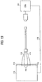
- FIG. 13 is a perspective view of the regenerator, for use in a Stirling cycle based system, of the fifth embodiment.
- This regenerator 1 is produced by winding up a resin film 2 into a cylindrical shape. With respect to the direction of the flow of the working gas indicated by an arrow 20, the regenerator 1, at its upstream-side end, communicates with the compression space 9 (see Fig. 3) and, at its downstream-side end, communicates with the expansion space 10 (see Fig. 3).
- top-side ribs 3a and a plurality of back-side ribs 3b are formed integrally at regular intervals and parallel to one another.
- the top-side ribs 3a and the back-side ribs 3b are inclined in opposite directions relative to the axis of the regenerator 1.
- the top-side ribs 3a and the back-side ribs 3b are formed, relative to the axis, at inclination angles that decrease stepwise toward the end at which the regenerator 1 communicates with the expansion space 10.
Landscapes
- Engineering & Computer Science (AREA)
- Chemical & Material Sciences (AREA)
- Mechanical Engineering (AREA)
- General Engineering & Computer Science (AREA)
- Combustion & Propulsion (AREA)
- Analytical Chemistry (AREA)
- Power Engineering (AREA)
- Physics & Mathematics (AREA)
- Thermal Sciences (AREA)
- Heat-Exchange Devices With Radiators And Conduit Assemblies (AREA)
- Laminated Bodies (AREA)
- Printing Methods (AREA)
Abstract
Description
- The present invention relates to a regenerator for use in a Stirling refrigerator, i.e. a refrigerator based on the principle of the Stirling cycle, for the purpose of accumulating the heat of working gas.
- Figs. 1 and 2 show a conventional regenerator designed for use in a Stirling cycle based system. This
regenerator 1 is produced by forming irregularities on the surface of aresin film 2 by bonding a plurality ofextra-fine spacers 4 at regular intervals and parallel to one another, and then winding theresin film 2 up into a cylindrical shape. - Fig. 3 shows an example of a Stirling refrigerator of a free piston type provided with a
regenerator 1 as described just above. This Stirling refrigerator has acylinder 8 filled with working gas such as helium, apiston 5 and adisplacer 7 for dividing the space inside thecylinder 8 into a compression space 9 and anexpansion space 10, a linear motor 6 for driving the reciprocating movement of thepiston 5,plate springs 11 and 12 for supporting thepiston 5 and the displacer 7 in such a way as to permit, by resilience, their reciprocating movement, a heat absorber 14 provided at theexpansion space 10 so as to absorb heat from the outside, and a heat dissipater 13 provided at the compression space 9 so as to dissipate heat to the outside. - Reference numeral 15 represents a heat exchanger for heat dissipation, and
reference numeral 16 represents a heat exchanger for heat absorption. These heat exchangers serve to prompt the exchange of heat between the inside and the outside, and theregenerator 1 is arranged between these exchangers. - In this Stirling refrigerator having the structure described above, when the linear motor 6 is driven, the
piston 5 moves upward inside thecylinder 8, compressing the working gas inside the compression space 9. During this time, although the temperature of the working gas rises, the heat is dissipated through the heat-dissipation heat exchanger 15 and then through the heat dissipater 13 to the outside air, and thus the working gas is cooled, achieving isothermal compression. The working gas compressed inside the compression space 9 is, by its own pressure, transferred through theregenerator 1 into theexpansion space 10. During this time, the heat of the working gas is accumulated in theresin film 2 constituting theregenerator 1, causing the temperature of the working gas to fall. - A predetermined phase difference is kept between the reciprocating movement of the
displacer 7 and that of thepiston 5. When thedisplacer 7 moves downward, the working gas inside theexpansion space 10 expands. During this time, although the temperature of the working gas falls, heat is absorbed from the outside air through the heat absorber 14 and then through the heat-absorption heat exchanger 16, and thus the working gas is heated, achieving isothermal expansion. A while later, when thedisplacer 7 starts moving upward, the working gas inside theexpansion space 10 is transferred through theregenerator 1 back to the compression space 9. During this time, the heat that has previously been accumulated in theregenerator 1 is transferred to the working gas, causing the temperature of the working gas to rise. This sequence of events, called the Stirling cycle, is repeated by the reciprocating movement of thepiston 5 and thedisplacer 7, and, as a result, heat is steadily absorbed through the heat absorber 14 and transferred to the working gas, gradually cooling theabsorber 14. - In this way, in the Stirling refrigerator, by transferring the working gas back and forth between the compression space 9 and the
expansion space 10 through theregenerator 1, heat is absorbed from the outside air so as to achieve the cooling of theabsorber 14. Meanwhile, theregenerator 1 accumulates heat from the working gas in its compressed, and thus hot, state, and transfers the heat back to the working gas in its expanded, and thus cold, state. Here, the larger the amount of heat so accumulated, the higher the heat exchange efficiency, and thus the higher the cooling performance of the Stirling refrigerator. - However, the above-described
conventional regenerator 1 for use in a Stirling cycle based system is very expensive because it requires undue time and labor for its production, which involves the bonding, one by one, of thespacers 4 on the surface of theresin film 2. Moreover, as shown in Fig. 4, the working gas passing through the gaps between different turns of theresin film 2, as it passes from the edge of theregenerator 1 inward, tends to move away from the surfaces of theresin film 2 and concentrate roughly at the center of the gaps, because boundary layers develop (in the figure,arrows 20 indicate the flow of the working gas). This lowers the heat transfer rate between the working gas and theresin film 2. - An object of the present invention is to provide an inexpensive regenerator for use in a Stirling cycle based system by simplifying the production process thereof.
- Another object of the present invention is to achieve satisfactorily high heat accumulation performance.
- To achieve the above objects, according to one aspect of the present invention, a regenerator for use in a Stirling cycle based system, such as is arranged between a compression space and an expansion space of the Stirling cycle based system so as to serve as a flow passage for working gas transferred back and forth between the compression space and the expansion space and simultaneously serve to accumulate the heat of the working gas, is produced by forming a plurality of ribs integrally on a surface of a resin film and winding the resin film up into a cylindrical shape.
- According to another aspect of the present invention, a regenerator for use in a Stirling cycle based system, such as is arranged between a compression space and an expansion space of the Stirling cycle based system so as to serve as a flow passage for working gas transferred back and forth between the compression space and the expansion space and simultaneously serve to accumulate the heat of the working gas, is produced by joining together two or more cores in the direction of the axes of the cores. Here, the cores are each produced by forming a plurality of ribs integrally on a surface of a resin film and winding the resin film up into a cylindrical shape.
- According to still another aspect of the present invention, a regenerator for use in a Stirling cycle based system, such as is arranged between a compression space and an expansion space of the Stirling cycle based system so as to serve as a flow passage for working gas transferred back and forth between the compression space and the expansion space and simultaneously serve to accumulate the heat of the working gas, is produced by forming a plurality of ribs integrally on both surfaces of a resin film and winding the resin film up into a cylindrical shape. Here, the ribs are inclined relative to the axis of the regenerator.
- This and other objects and features of the present invention will become clear from the following description, taken in conjunction with the preferred embodiments with reference to the accompanying drawings in which:
- Fig. 1 is a perspective view of a conventional regenerator for use in a Stirling cycle based system;
- Fig. 2 is an enlarged view of a principal portion of the conventional regenerator;
- Fig. 3 is a sectional view of a typical Stirling refrigerator as seen from the side;
- Fig. 4 is a diagram illustrating the flow of the working gas passing through the inside of the conventional regenerator;
- Fig. 5 is a perspective view of the regenerator, for use in a Stirling cycle based system, of a first embodiment of the invention;
- Fig. 6 is an enlarged view of a principal portion of the regenerator of the first embodiment;
- Fig. 7 is a perspective view of the regenerator, for use in a Stirling cycle based system, of a second embodiment of the invention;
- Fig. 8 is a perspective view of the regenerator, for use in a Stirling cycle based system, of a third embodiment of the invention;
- Fig. 9 is a perspective view of the regenerator, for use in a Stirling cycle based system, of a fourth embodiment of the invention;
- Fig. 10 is an enlarged view of a principal portion of the regenerator of the fourth embodiment;
- Fig. 11 is a diagram illustrating the flow of the working gas passing through the inside of the regenerator of the fourth embodiment;
- Fig. 12 is a diagram showing the result of performance evaluation of the regenerator of the fourth embodiment; and
- Fig. 13 a perspective view of the regenerator, for use in a Stirling cycle based system, of a fifth embodiment of the invention.
-
- Hereinafter, embodiments of the present invention will be described in more detail with reference to the accompanying drawings.
- A first embodiment of the invention will be described below with reference to Figs. 5 and 6. Fig. 5 is a perspective view of the regenerator, for use in a Stirling cycle based system, of the first embodiment, and Fig. 6 is an enlarged view of a principal portion thereof. This
regenerator 1 is produced by winding up aresin film 2 into a cylindrical shape. On the surface of theresin film 2, a plurality ofribs 3 are formed integrally with theresin film 2 at regular intervals and parallel to the axis of theregenerator 1. - The
resin film 2 is preferably made of a material having high specific heat, low heat conductivity, high heat resistance, low moisture absorbency, and other desirable properties, for example polyethylene terephthalate (PET), a polyimide, or the like. Theribs 3 are preferably formed, for example, by applying photo-curing ink to the surface of theresin film 2 and then applying screen printing thereto, or by pressing a heated metal mold against the surface of the resin film 2 (a thermoforming process). - The
regenerator 1 of this embodiment employs aresin film 2 havingribs 3 formed integrally on the surface thereof, and thus can be produced at lower cost and with more ease than a conventional regenerator that requires the bonding of spacers. - A second embodiment of the invention will be described below with reference to Fig. 7. Fig. 7 is a perspective view of the regenerator, for use in a Stirling cycle based system, of the second embodiment. This
regenerator 1 is produced by joining together three cylinder-shaped regenerator cores 1a, 1b, and 1c of identical size in the direction of the axes thereof. The regenerator cores 1a, 1b, and 1c are each produced by forming a plurality ofribs 3 integrally on the surface of aresin film 2 at regular intervals and parallel to the axis of the core and then winding up theresin film 2 into a cylindrical shape. Theribs 3 are formed at the same intervals in all of the regenerator cores 1a, 1b, and 1c. - The
regenerator 1 of this embodiment is produced by joining together shorter regenerator cores 1a, 1b, and 1c, and therefore some of theribs 3 are left discontinuous between adjacent cores. As a result, when the working gas, flowing from the direction indicated by anarrow 20 and then passing between theribs 3 of the regenerator core 1c, flows into the regenerator core 1b, it collides with theribs 3 of the regenerator core 1b and thereby its flow is disturbed. Thus, boundary layers are cut off before developing. The same occurs when the working gas passes from the regenerator core 1b to the regenerator core 1a. - In this way, the development of boundary layers at the seams between the regenerator cores 1a, 1b, and 1c is prevented, and this helps reduce the lowering of the heat transfer rate between the working gas and the
resin film 2. Thus, theregenerator 1 of this embodiment offers much higher heat accumulation performance than a conventional regenerator or the regenerator of the first embodiment where theregenerator 1 is composed of a single core. Moreover, since theribs 3 are formed at regular intervals and parallel to each other, theresin film 2 can be mass-produced with minimal variations in performance among the regenerator cores 1a, 1b, and 1c. - It is to be understood that, although this embodiment deals with a case where the
regenerator 1 is composed of three regenerator cores 1a, 1b, and 1c, it is also possible to use more regenerator cores in expectation of still higher heat accumulation performance. - A third embodiment of the invention will be described below with reference to Fig. 8. Fig. 8 is a perspective view of the regenerator, for use in a Stirling cycle based system, of the third embodiment. This
regenerator 1 is produced, as in the second embodiment, by joining together three cylinder-shaped regenerator cores 1a, 1b, and 1c of identical size in the direction of the axes thereof. Here, theregenerator 1, at its end on the regenerator core 1a side, communicates with the expansion space 10 (see Fig. 3), and, at its end on the regenerator core 1c side, communicates with the compression space 9 (see Fig. 3). - In each of the regenerator cores 1a, 1b, and 1c, a plurality of
ribs 3 are formed integrally at regular intervals and parallel to the axis thereof. Theseribs 3 are formed at intervals that increase stepwise toward theexpansion space 10; that is, they are formed at longer intervals in the regenerator core 1b than in the regenerator core 1c, and at longer intervals in the regenerator core 1a than in the regenerator core 1b. - While the working gas, flowing from the compression space 9 (i.e. from the direction indicated by an arrow 20), is passing through the inside of the
regenerator 1, its heat is absorbed by the heat accumulation effect of theregenerator 1, and thus, as the working gas approaches theexpansion space 10, its temperature gradually falls. According as the working gas becomes colder, its density becomes higher, and thus its flowability becomes lower. Therefore, according as the working gas approaches theexpansion space 10, its flow becomes less smooth. This is the reason that, in this embodiment, theribs 3 are formed at intervals that increase toward theexpansion space 10. This helps make almost uniform the flow resistance against the working gas throughout theregenerator 1 and thereby achieve optimal flowability and uniform flow-rate distribution of the working gas. Thus, theregenerator 1 of this embodiment, where also the development of boundary layers is prevented by the joining together of the regenerator cores 1a, 1b, and 1c, offers even higher heat accumulation performance. - A fourth embodiment of the invention will be described below with reference to Figs. 9 and 10. Fig. 9 is a perspective view of the regenerator, for use in a Stirling cycle based system, of the fourth embodiment, and Fig. 10 is an enlarged view of a principal portion thereof. This
regenerator 1 is produced by winding up aresin film 2 into a cylindrical shape. On both the top and bottom surfaces of theresin film 2, a plurality of top-side ribs (indicated by solid lines 3a in Fig. 9) and a plurality of back-side ribs (indicated by dotted lines 3b in Fig. 9), respectively, are formed integrally at regular intervals and parallel to one another. The top-side ribs 3a and the back-side ribs 3b are inclined in opposite directions relative to the axis of theregenerator 1. Thus, when theresin film 2 is wound up, overlapping turns thereof make contact with one another at the intersections between the top-side ribs 3a of one turn and the back-side ribs 3b of another, and this helps secure gaps that serve as flow passages for the working gas. - As shown in Fig. 11, when the working gas, flowing from the direction indicated by an
arrow 20, passes through the gaps between different turns of theresin film 2, it collides with the top-side ribs 3a and the back-side ribs 3b protruding from below and from above, and thereby its flow is disturbed, causing eddies to appear. As a result, the boundary layers that have been developing from the edge of theregenerator 1 are cut off by the top-side ribs 3a and the back-side ribs 3b. This helps improve the heat transfer rate between the working gas and theresin film 2. Thus, theregenerator 1 of this embodiment, where the top-side ribs 3a and the back-side ribs 3b also serve to secure a wider heat transfer surface area, offers far higher heat accumulating performance. - Moreover, the top-side ribs 3a, and also the back-side ribs 3b, are formed at regular intervals and parallel to one another, and therefore the intersections at which the top-side ribs 3a and the back-side ribs 3b make contact with each other are distributed evenly over the
entire resin film 2. Thus, theregenerator 1 of this embodiment offers stable heat accumulation performance with almost no variations. - Next, the result of performance evaluation conducted with an actually produced sample of the
regenerator 1 for use in a Stirling cycle based system of the fourth embodiment described above will be presented. The table below lists the specifications of the ribbed resin film employed in this regenerator.Film Material Polyethylene terephthalate Thickness 70 (µm) Ribs Material UV ink Formation process Screen printing Width 100 (µm) Height 35 (µm) Pitch 2 (mm) Angle relative to winding direction 15 (deg.) - A resin film having the above-listed specifications was wound up into a cylindrical shape to produce a regenerator for use in a Stirling cycle based system. This regenerator was fitted inside the cylinder of a Stirling refrigerator, and the working gas was transferred back and forth between the compression space and the expansion space at varying reciprocating flow rates G (L/m) to determine the regenerator efficiency η. In addition, for comparison, the same performance evaluation was conducted also with a conventional regenerator (see Fig. 1) produced using a resin film having spacers bonded on the surface thereof
- The regenerator efficiency η mentioned above serves as an index for evaluating the heat accumulation performance of a regenerator designed for use in a Stirling cycle based system, and is given by the following formula:
- Thin represents the temperature of the working gas immediately before the working gas compressed in the compression space flows into the regenerator;
- Thout represents the temperature of the working gas immediately after the working gas flows out of the regenerator into the expansion space;
- Tcin represents the temperature of the working gas immediately before the working gas flows out of the expansion space into the regenerator; and
- Tcout represents the temperature of the working gas immediately after the working gas flows out of the regenerator into the compressed space.
-
- In a Stirling cycle based system, the following relations hold:
- Fig. 12 shows the result of the performance evaluation described above. In this figure,
reference numeral 30 indicates a graph of the regenerator efficiency of a regenerator that adopts a structure according to the present invention, and reference numeral 31 indicates a graph of the regenerator efficiency of a regenerator that adopts a conventional structure. As shown in this figure, even if the reciprocating flow rate varies, the regenerator that adopts a structure according to the present invention offers higher regenerator efficiency and thus higher heat accumulation performance than the regenerator that adopts a conventional structure. - A fifth embodiment of the invention will be described below with reference to Fig. 13. Fig. 13 is a perspective view of the regenerator, for use in a Stirling cycle based system, of the fifth embodiment. This
regenerator 1 is produced by winding up aresin film 2 into a cylindrical shape. With respect to the direction of the flow of the working gas indicated by anarrow 20, theregenerator 1, at its upstream-side end, communicates with the compression space 9 (see Fig. 3) and, at its downstream-side end, communicates with the expansion space 10 (see Fig. 3). - On both the top and bottom surfaces of the
resin film 2, a plurality of top-side ribs 3a and a plurality of back-side ribs 3b, respectively, are formed integrally at regular intervals and parallel to one another. The top-side ribs 3a and the back-side ribs 3b are inclined in opposite directions relative to the axis of theregenerator 1. Moreover, the top-side ribs 3a and the back-side ribs 3b are formed, relative to the axis, at inclination angles that decrease stepwise toward the end at which theregenerator 1 communicates with theexpansion space 10. - As described previously, according as the working gas approaches the
expansion space 10, its temperature falls, and its density becomes higher. By forming the top-side ribs 3a and the back-side ribs 3b at inclination angles that decrease stepwise in accordance with the increase in the density of the working gas, it is possible to reduce the flow resistance against the working gas in a portion of theregenerator 1 near theexpansion space 10, and thereby readily achieve optimal flowability and uniform flow-rate distribution of the working gas. - It is to be understood that, although this embodiment deals with a case where the inclination angles of the ribs are changed in three steps, it is also possible to change them in more steps to gain the above-noted advantages to a greater extent.
Claims (21)
- A regenerator (1) for use in a Stirling cycle based system, the regenerator (1) being arranged between a compression space (9) and an expansion space (10) of the Stirling cycle based system so as to serve as a flow passage for working gas transferred back and forth between the compression space (9) and the expansion space (10) and simultaneously serve to accumulate heat of the working gas,
wherein the regenerator (1) is produced by forming a plurality of ribs (3) integrally on a surface of a resin film (2) and winding the resin film (2) up into a cylindrical shape. - A regenerator (1) for use in a Stirling cycle based system as claimed in claim 1,
wherein the ribs (3) are formed at regular intervals and parallel to an axis of the regenerator (1). - A regenerator (1) for use in a Stirling cycle based system as claimed in claim 1,
wherein the resin film (2) is made of polyethylene terephthalate. - A regenerator (1) for use in a Stirling cycle based system as claimed in claim 1,
wherein the resin film (2) is made of a polyimide. - A regenerator (1) for use in a Stirling cycle based system as claimed in claim 1,
wherein the ribs (3) are formed by applying photo-curing ink to the surface of the resin film (2) and then applying screen printing thereto. - A regenerator (1) for use in a Stirling cycle based system as claimed in claim 1,
wherein the ribs (3) are formed by pressing a heated metal mold against the surface of the resin film (2). - A regenerator (1) for use in a Stirling cycle based system, the regenerator (1) being arranged between a compression space (9) and an expansion space (10) of the Stirling cycle based system so as to serve as a flow passage for working gas transferred back and forth between the compression space (9) and the expansion space (10) and simultaneously serve to accumulate heat of the working gas,
wherein the regenerator (1) is produced by joining together two or more cores (1a, 1b, 1c) in a direction of axes of the cores (1a, 1b, 1c), the cores (1a, 1b, 1c) being each produced by forming a plurality of ribs (3) integrally on a surface of a resin film (2) and winding the resin film (2) up into a cylindrical shape. - A regenerator (1) for use in a Stirling cycle based system as claimed in claim 7,
wherein the ribs (3) are formed at regular intervals and parallel to the axes of the cores (1a, 1b, 1c). - A regenerator (1) for use in a Stirling cycle based system as claimed in claim 7,
wherein the resin film (2) is made of polyethylene terephthalate. - A regenerator (1) for use in a Stirling cycle based system as claimed in claim 7,
wherein the resin film (2) is made of a polyimide. - A regenerator (1) for use in a Stirling cycle based system as claimed in claim 7,
wherein the ribs (3) are formed by applying photo-curing ink to the surface of the resin film (2) and then applying screen printing thereto. - A regenerator (1) for use in a Stirling cycle based system as claimed in claim 7,
wherein the ribs (3) are formed by pressing a heated metal mold against the surface of the resin film (2). - A regenerator (1) for use in a Stirling cycle based system as claimed in claim 7,
wherein the ribs (3) are formed at intervals that increase toward the expansion space (10). - A regenerator (1) for use in a Stirling cycle based system, the regenerator (1) being arranged between a compression space (9) and an expansion space (10) of the Stirling cycle based system so as to serve as a flow passage for working gas transferred back and forth between the compression space (9) and the expansion space (10) and simultaneously serve to accumulate heat of the working gas,
wherein the regenerator (1) is produced by forming a plurality of ribs (3a, 3b) integrally on both surfaces of a resin film (2) and winding the resin film (2) up into a cylindrical shape, the ribs (3a, 3b) being inclined relative to an axis of the regenerator (1). - A regenerator (1) for use in a Stirling cycle based system as claimed in claim 14,
wherein the ribs (3a, 3b) are inclined in opposite directions on one and the other surfaces of the resin film (2). - A regenerator (1) for use in a Stirling cycle based system as claimed in claim 14,
wherein the ribs (3a, 3b) are formed at regular intervals and parallel to one another. - A regenerator (1) for use in a Stirling cycle based system as claimed in claim 14,
wherein the resin film (2) is made of polyethylene terephthalate. - A regenerator (1) for use in a Stirling cycle based system as claimed in claim 14,
wherein the resin film (2) is made of a polyimide. - A regenerator (1) for use in a Stirling cycle based system as claimed in claim 14,
wherein the ribs (3a, 3b) are formed by applying photo-curing ink to the surfaces of the resin film (2) and then applying screen printing thereto. - A regenerator (1) for use in a Stirling cycle based system as claimed in claim 14,
wherein the ribs (3a, 3b) are formed by pressing a heated metal mold against the surfaces of the resin film (2). - A regenerator (1) for use in a Stirling cycle based system as claimed in claim 14,
wherein the ribs (3a, 3b) are formed at inclination angles that decrease toward the expansion space (10).
Applications Claiming Priority (2)
| Application Number | Priority Date | Filing Date | Title |
|---|---|---|---|
| JP2132199 | 1999-01-29 | ||
| JP02132199A JP3583637B2 (en) | 1999-01-29 | 1999-01-29 | Regenerator for Stirling engine |
Publications (4)
| Publication Number | Publication Date |
|---|---|
| EP1024277A2 true EP1024277A2 (en) | 2000-08-02 |
| EP1024277A3 EP1024277A3 (en) | 2001-06-27 |
| EP1024277A9 EP1024277A9 (en) | 2004-09-08 |
| EP1024277B1 EP1024277B1 (en) | 2005-03-30 |
Family
ID=12051901
Family Applications (1)
| Application Number | Title | Priority Date | Filing Date |
|---|---|---|---|
| EP00101787A Expired - Lifetime EP1024277B1 (en) | 1999-01-29 | 2000-01-28 | Regenerator for a stirling cycle based system |
Country Status (5)
| Country | Link |
|---|---|
| US (1) | US6474075B1 (en) |
| EP (1) | EP1024277B1 (en) |
| JP (1) | JP3583637B2 (en) |
| KR (1) | KR100352961B1 (en) |
| DE (1) | DE60019006T2 (en) |
Families Citing this family (15)
| Publication number | Priority date | Publication date | Assignee | Title |
|---|---|---|---|---|
| JP3690980B2 (en) * | 2000-11-30 | 2005-08-31 | シャープ株式会社 | Stirling agency |
| JP2002295914A (en) * | 2001-03-30 | 2002-10-09 | Ekuteii Kk | Sheet type cold storage material, method for producing the same, and regenerator and refrigerator using the same |
| US6854509B2 (en) * | 2001-07-10 | 2005-02-15 | Matthew P. Mitchell | Foil structures for regenerators |
| JP2003065620A (en) * | 2001-08-22 | 2003-03-05 | Sharp Corp | Regenerator for Stirling machine, Stirling refrigerator using the regenerator, and heat regeneration system for flowing gas |
| US6694730B2 (en) * | 2002-05-30 | 2004-02-24 | Superconductor Technologies, Inc. | Stirling cycle cryocooler with improved magnet ring assembly and gas bearings |
| KR20040033764A (en) * | 2002-10-15 | 2004-04-28 | 주명자 | Stirling machinery regenerator |
| EP1580497B1 (en) * | 2002-10-31 | 2008-04-30 | Sharp Kabushiki Kaisha | Regenerator, method for manufacturing regenerator, system for manufacturing regenerator and stirling refrigerating machine |
| US6688113B1 (en) * | 2003-02-11 | 2004-02-10 | Superconductor Technologies, Inc. | Synthetic felt regenerator material for stirling cycle cryocoolers |
| US20050056036A1 (en) * | 2003-09-17 | 2005-03-17 | Superconductor Technologies, Inc. | Integrated cryogenic receiver front-end |
| US8096118B2 (en) | 2009-01-30 | 2012-01-17 | Williams Jonathan H | Engine for utilizing thermal energy to generate electricity |
| LT5969B (en) | 2012-03-09 | 2013-11-25 | Uab "Modernios E-Technologijos" | Regenerator with direct heat exchange for multi-cylinder stirling cycle device |
| US20140264979A1 (en) * | 2013-03-13 | 2014-09-18 | Transitions Opticals, Inc. | Method of preparing photochromic-dichroic films having reduced optical distortion |
| US20140265010A1 (en) * | 2013-03-13 | 2014-09-18 | Transitions Optical, Inc. | Method of preparing photochromic-dichroic films having reduced optical distortion |
| JP6386230B2 (en) * | 2014-02-03 | 2018-09-05 | 東邦瓦斯株式会社 | Thermal accumulator for thermoacoustic devices |
| EP3117090A1 (en) * | 2014-03-12 | 2017-01-18 | NV Bekaert SA | Regenerator for a thermal cycle engine |
Family Cites Families (8)
| Publication number | Priority date | Publication date | Assignee | Title |
|---|---|---|---|---|
| NL6401013A (en) | 1964-02-07 | 1965-08-09 | ||
| GB1354502A (en) | 1970-08-28 | 1974-06-05 | Ici Ltd | Heat exchangers |
| JPS62177186A (en) * | 1986-01-29 | 1987-08-04 | Ishikawajima Harima Heavy Ind Co Ltd | Manufacturing method of plate fin type heat exchanger |
| US4866943A (en) * | 1988-10-17 | 1989-09-19 | Cdc Partners | Cyrogenic regenerator |
| GB9104156D0 (en) | 1991-02-27 | 1991-04-17 | Rolls Royce & Ass | Heat exchanger |
| US5429177A (en) * | 1993-07-09 | 1995-07-04 | Sierra Regenators, Inc. | Foil regenerator |
| US5445216A (en) | 1994-03-10 | 1995-08-29 | Cannata; Antonio | Heat exchanger |
| BE1011595A3 (en) | 1997-12-09 | 1999-11-09 | Ewa Nova Bvba Besloten Vennoot | Improved heat exchanger and method to realise such a heat exchanger |
-
1999
- 1999-01-29 JP JP02132199A patent/JP3583637B2/en not_active Expired - Fee Related
-
2000
- 2000-01-12 US US09/481,395 patent/US6474075B1/en not_active Expired - Fee Related
- 2000-01-28 DE DE60019006T patent/DE60019006T2/en not_active Expired - Lifetime
- 2000-01-28 EP EP00101787A patent/EP1024277B1/en not_active Expired - Lifetime
- 2000-01-28 KR KR1020000004160A patent/KR100352961B1/en not_active Expired - Fee Related
Non-Patent Citations (1)
| Title |
|---|
| None |
Also Published As
| Publication number | Publication date |
|---|---|
| JP3583637B2 (en) | 2004-11-04 |
| US6474075B1 (en) | 2002-11-05 |
| DE60019006T2 (en) | 2006-03-30 |
| DE60019006D1 (en) | 2005-05-04 |
| EP1024277A9 (en) | 2004-09-08 |
| JP2000220897A (en) | 2000-08-08 |
| KR100352961B1 (en) | 2002-09-18 |
| EP1024277B1 (en) | 2005-03-30 |
| KR20000053649A (en) | 2000-08-25 |
| EP1024277A3 (en) | 2001-06-27 |
Similar Documents
| Publication | Publication Date | Title |
|---|---|---|
| EP1024277B1 (en) | Regenerator for a stirling cycle based system | |
| CA1317772C (en) | Condenser with small hydraulic diameter flow path | |
| US6779342B2 (en) | Stirling engine | |
| EP1422484B1 (en) | Regenerator, and heat regenerative system for fluidized gas using the regenerator | |
| CN100473935C (en) | Involute foil regenerator | |
| KR102682206B1 (en) | Battery Cooling Module based on a Pulsating Heat Pipe and Battery Unit Including The Same | |
| JPH07198284A (en) | Heat exchanger | |
| CN113329593A (en) | Integrated low-temperature semiconductor chip system | |
| JP2003166766A (en) | Heat exchanger for pulse pipe refrigerator | |
| JP2004132696A (en) | Regenerator for Stirling engine | |
| JP3563679B2 (en) | Heat exchanger and heat exchanger body for Stirling refrigerator | |
| KR100391948B1 (en) | Stirling machinery | |
| JP3263566B2 (en) | Gap heat exchanger for Stirling equipment | |
| CN113994158B (en) | Method for manufacturing heat storage device | |
| KR20060045109A (en) | Regenerator of cryogenic chiller and its manufacturing method and cryogenic chiller using the same | |
| JP2006258382A (en) | Stirling engine regenerator and Stirling refrigerator | |
| JPH0451662B2 (en) | ||
| KR20020090622A (en) | Stirling machinery | |
| JP2006207851A (en) | Regenerator, manufacturing method thereof, Stirling engine, Stirling cooler | |
| JPH09310929A (en) | Regenerater of hot-gas engine of external combustion type | |
| JPH09113047A (en) | Stirling apparatus | |
| KR20000014367A (en) | Heat exchanger of stirring machine |
Legal Events
| Date | Code | Title | Description |
|---|---|---|---|
| PUAI | Public reference made under article 153(3) epc to a published international application that has entered the european phase |
Free format text: ORIGINAL CODE: 0009012 |
|
| AK | Designated contracting states |
Kind code of ref document: A2 Designated state(s): DE FR GB SE |
|
| AX | Request for extension of the european patent |
Free format text: AL;LT;LV;MK;RO;SI |
|
| PUAL | Search report despatched |
Free format text: ORIGINAL CODE: 0009013 |
|
| AK | Designated contracting states |
Kind code of ref document: A3 Designated state(s): AT BE CH CY DE DK ES FI FR GB GR IE IT LI LU MC NL PT SE |
|
| AX | Request for extension of the european patent |
Free format text: AL;LT;LV;MK;RO;SI |
|
| RIC1 | Information provided on ipc code assigned before grant |
Free format text: 7F 02G 1/057 A, 7F 28D 9/04 B |
|
| 17P | Request for examination filed |
Effective date: 20010905 |
|
| AKX | Designation fees paid |
Free format text: DE FR GB SE |
|
| RBV | Designated contracting states (corrected) |
Designated state(s): DE FR GB SE |
|
| GRAP | Despatch of communication of intention to grant a patent |
Free format text: ORIGINAL CODE: EPIDOSNIGR1 |
|
| GRAS | Grant fee paid |
Free format text: ORIGINAL CODE: EPIDOSNIGR3 |
|
| GRAA | (expected) grant |
Free format text: ORIGINAL CODE: 0009210 |
|
| AK | Designated contracting states |
Kind code of ref document: B1 Designated state(s): DE FR GB SE |
|
| REG | Reference to a national code |
Ref country code: GB Ref legal event code: FG4D |
|
| REF | Corresponds to: |
Ref document number: 60019006 Country of ref document: DE Date of ref document: 20050504 Kind code of ref document: P |
|
| REG | Reference to a national code |
Ref country code: SE Ref legal event code: TRGR |
|
| ET | Fr: translation filed | ||
| PLBE | No opposition filed within time limit |
Free format text: ORIGINAL CODE: 0009261 |
|
| STAA | Information on the status of an ep patent application or granted ep patent |
Free format text: STATUS: NO OPPOSITION FILED WITHIN TIME LIMIT |
|
| 26N | No opposition filed |
Effective date: 20060102 |
|
| PGFP | Annual fee paid to national office [announced via postgrant information from national office to epo] |
Ref country code: SE Payment date: 20091218 Year of fee payment: 11 |
|
| PGFP | Annual fee paid to national office [announced via postgrant information from national office to epo] |
Ref country code: FR Payment date: 20100208 Year of fee payment: 11 |
|
| PGFP | Annual fee paid to national office [announced via postgrant information from national office to epo] |
Ref country code: GB Payment date: 20100202 Year of fee payment: 11 Ref country code: DE Payment date: 20100121 Year of fee payment: 11 |
|
| REG | Reference to a national code |
Ref country code: SE Ref legal event code: EUG |
|
| GBPC | Gb: european patent ceased through non-payment of renewal fee |
Effective date: 20110128 |
|
| REG | Reference to a national code |
Ref country code: FR Ref legal event code: ST Effective date: 20110930 |
|
| PG25 | Lapsed in a contracting state [announced via postgrant information from national office to epo] |
Ref country code: FR Free format text: LAPSE BECAUSE OF NON-PAYMENT OF DUE FEES Effective date: 20110131 |
|
| PG25 | Lapsed in a contracting state [announced via postgrant information from national office to epo] |
Ref country code: GB Free format text: LAPSE BECAUSE OF NON-PAYMENT OF DUE FEES Effective date: 20110128 |
|
| REG | Reference to a national code |
Ref country code: DE Ref legal event code: R119 Ref document number: 60019006 Country of ref document: DE Effective date: 20110802 |
|
| PG25 | Lapsed in a contracting state [announced via postgrant information from national office to epo] |
Ref country code: SE Free format text: LAPSE BECAUSE OF NON-PAYMENT OF DUE FEES Effective date: 20110129 |
|
| PG25 | Lapsed in a contracting state [announced via postgrant information from national office to epo] |
Ref country code: DE Free format text: LAPSE BECAUSE OF NON-PAYMENT OF DUE FEES Effective date: 20110802 |