EP1024042A2 - Foldable top for convertible vehicle - Google Patents
Foldable top for convertible vehicle Download PDFInfo
- Publication number
- EP1024042A2 EP1024042A2 EP99125467A EP99125467A EP1024042A2 EP 1024042 A2 EP1024042 A2 EP 1024042A2 EP 99125467 A EP99125467 A EP 99125467A EP 99125467 A EP99125467 A EP 99125467A EP 1024042 A2 EP1024042 A2 EP 1024042A2
- Authority
- EP
- European Patent Office
- Prior art keywords
- folding
- hood according
- expansion strut
- strut
- tensioning bracket
- Prior art date
- Legal status (The legal status is an assumption and is not a legal conclusion. Google has not performed a legal analysis and makes no representation as to the accuracy of the status listed.)
- Granted
Links
Images


Classifications
-
- B—PERFORMING OPERATIONS; TRANSPORTING
- B60—VEHICLES IN GENERAL
- B60J—WINDOWS, WINDSCREENS, NON-FIXED ROOFS, DOORS, OR SIMILAR DEVICES FOR VEHICLES; REMOVABLE EXTERNAL PROTECTIVE COVERINGS SPECIALLY ADAPTED FOR VEHICLES
- B60J7/00—Non-fixed roofs; Roofs with movable panels, e.g. rotary sunroofs
- B60J7/08—Non-fixed roofs; Roofs with movable panels, e.g. rotary sunroofs of non-sliding type, i.e. movable or removable roofs or panels, e.g. let-down tops or roofs capable of being easily detached or of assuming a collapsed or inoperative position
- B60J7/12—Non-fixed roofs; Roofs with movable panels, e.g. rotary sunroofs of non-sliding type, i.e. movable or removable roofs or panels, e.g. let-down tops or roofs capable of being easily detached or of assuming a collapsed or inoperative position foldable; Tensioning mechanisms therefor, e.g. struts
- B60J7/1226—Soft tops for convertible vehicles
- B60J7/1265—Soft tops for convertible vehicles characterised by kinematic movements, e.g. using parallelogram linkages
Landscapes
- Engineering & Computer Science (AREA)
- Mechanical Engineering (AREA)
- Body Structure For Vehicles (AREA)
- Rear-View Mirror Devices That Are Mounted On The Exterior Of The Vehicle (AREA)
- Tents Or Canopies (AREA)
Abstract
Description
Die Erfindung bezieht sich auf ein Faltverdeck für ein Cabriolet-Fahrzeug
in einer Ausbildung gemäß dem Oberbegriff
des Anspruchs 1.The invention relates to a folding top for a convertible vehicle
in training according to the generic term
of
Die Erfindung befaßt sich mit dem Problem, ein Cabriolet-Fahrzeug mit einem Faltverdeck der gemäß DE 295 13 595.6 bekannten Art zu schaffen, dessen Verdeckkinematik mit geringem technischem Aufwand bei der Öffnungs- bzw. Schließbewegung des Verdecks eine verminderte Beeinträchtigung von Fahrzeuginsassen ermöglicht und dabei insgesamt einen verbesserten Bedienkomfort aufweist.The invention addresses the problem of a convertible vehicle with a folding top according to DE 295 13 595.6 to create known type, the top kinematics with little technical effort in the opening or closing movement of the hood a reduced impairment enabled by vehicle occupants and a total of one has improved ease of use.
Die Erfindung löst diese Aufgabe durch ein Faltverdeck mit
den Merkmalen des Anspruchs 1. Hinsichtlich wesentlicher
weiterer Ausgestaltungsmerkmale wird auf die Ansprüche 2
bis 16 verwiesen.The invention solves this problem with a folding roof
the features of
Das erfindungsgemäße Faltverdeck weist im heckseitigen Bereich seiner beiden randseitigen Klappgestänge-Baugruppen jeweils eine aus der an sich bekannten Hauptsäule und einer an dieser außenseitig angelenkten Spreizstrebe bestehende, zweiteilige Gestängegruppe als Verbindungseinheit zur Dachhaut auf. Diese Spreizstrebe ist längsrandseitig mit einem Bereich der Dachhaut so verbunden, daß eine von der Hauptsäule unabhängige Anbindung geschaffen ist und der heckseitige Bereich der Dachhaut auch unabhängig von der Bewegung der Hauptsäule gespannt bzw. entspannt werden kann. Die im heckseitigen Bereich in die Dachhhaut integrierte Heckscheibe kann mit dieser Verdeckkinematik über einen vergrößerten Verstellbereich so verlagert werden, daß die Stützbauteile in eine Hochstellung gelangen und dabei eine über dem Fondbereich des Fahrzeugs als Kopffreiheit wirksame Bahnkurve durchlaufen wird.The folding top according to the invention has in the rear area its two edge-side folding link assemblies one each from the main pillar known per se and one existing on this externally articulated strut, two-part linkage group as connection unit to the roof skin. This strut is on the longitudinal edge connected to an area of the roof skin so that one of the main pillar is connected independently and the rear area of the roof skin also independent of be tensioned or relaxed during the movement of the main column can. The one integrated into the roof membrane in the rear area Rear window can with this convertible top kinematics an enlarged adjustment range can be shifted that the support components come to a high position and one above the rear of the vehicle as headroom effective trajectory is traversed.
Bei der Öffnungs- bzw. Schließbewegung des Verdecks wirkt die Spreizstrebe mit einem den hinteren Randbereich der Dachhaut erfassenden Verdeckstoff-Spannbügel derart zusammen, daß eine weitgehend spannungsfreie und materialschonende Bewegung des Faltverdecks erreicht ist. Beim Öffnen des Faltverdecks werden der Verdeckspannbügel und die Spreizstrebe entgegen der Fahrtrichtung hochgeschwenkt, wobei der von beiden Bauteilen gehaltene Dachhaut-Heckbereich mit der integrierten Heckscheibe angehoben wird und durch die Bewegung der Spreizstrebe entgegen der Fahrtrichtung auch der vordere Randbereich der Heckscheibe die Hochstellung einnimmt.It works when the convertible top is opened or closed the strut with a the rear edge area of the Roof fabric clamping bracket capturing roof skin together in such a way that a largely tension-free and gentle on the material Movement of the folding top is reached. When opening of the folding top are the top tensioning bracket and the Spreading strut swung up against the direction of travel, where the roof skin rear area held by both components with the integrated rear window raised is and by the movement of the strut against the Direction of travel also the front edge area of the rear window takes the superscript.
Bei diesem Öffnungsvorgang des Faltverdecks bleibt ein im Fondbereich des Fahrzeug sitzender Passagier von der Bewegung der Heckscheibe unbeeinflußt, da deren vorderer Randbereich auf einer sich vom oberen Bereich des Innenraums bis hinter die Kopfstützen erstreckenden Bewegungsbahn geführt werden kann. Damit ist eine bisher als nachteilig empfundene Verlagerung von Verdeckteilen in das Gesichtsfeld des Insassen vermieden, gleichzeitig für große Personen im Fondbereich eine Gefährdung bei der Verdeckbewegung ausgeschlossen und mit dieser Verdeckkinematik der Bedienkomfort insgesamt verbessert.During this opening process of the folding top, an remains in the Rear area of the vehicle seated passenger from the movement the rear window unaffected, since its front edge area on one itself from the top of the interior led to the trajectory extending behind the headrests can be. So far, one has been disadvantageous perceived displacement of convertible top parts into the visual field of the occupant avoided, at the same time for tall people in the rear area there is a danger of the convertible top moving excluded and with this soft top kinematics the ease of use improved overall.
Weitere Einzelheiten und vorteilhafte Wirkungen der Erfindung ergeben sich aus der nachfolgenden Beschreibung und der Zeichnung, in der ein Ausführungsbeispiel des Gegenstands der Erfindung näher veranschaulicht ist. In der Zeichnung zeigen:
- Fig. 1
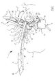
- eine Seitenansicht des ohne Dachhaut dargestellten Faltverdecks in Schließstellung,
- Fig. 2
- eine Seitenansicht ähnlich Fig. 1 in einer ersten Öffnungsphase bei Verstellung eines Verdeckstoff-Spannbügels und einer Spreizstrebe,
- Fig. 3
- eine zweite Öffnungsphase bei Bewegung des Klappgestänges zu einem heckseitigen Verdeckkasten hin,
- Fig. 4
- eine Seitenansicht mit im Verdeckkasten befindlichen Faltverdeck,
- Fig. 5
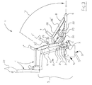
- eine perspektivische Ausschnittsdarstellung des Klappgestänges im Bereich der Hauptsäule in Schließstellung,
- Fig. 6
- eine Perspektivdarstellung ähnlich Fig. 5 während der Öffnungsphase gemäß Fig. 2 mit hochgeschwenktem Verdeckstoff-Spannbügel, und
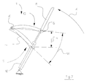
- Fig. 7
- eine Prinzipdarstellung einer zweiten Ausführung der Spreizstrebe mit direkt an dieser angelenktem Verdeckstoff-Spannbügel.
- Fig. 1
- a side view of the folding top shown without roof skin in the closed position,
- Fig. 2
- 2 shows a side view similar to FIG. 1 in a first opening phase when a top fabric tensioning bracket and an expansion strut are adjusted,
- Fig. 3
- a second opening phase when the folding linkage moves towards a rear-side convertible top compartment,
- Fig. 4
- a side view with the folding top located in the top compartment,
- Fig. 5
- 2 shows a perspective cutout view of the folding linkage in the area of the main column in the closed position
- Fig. 6
- a perspective view similar to FIG. 5 during the opening phase of FIG. 2 with the top fabric tensioning bracket pivoted up, and
- Fig. 7
- a schematic diagram of a second embodiment of the expanding strut with a top fabric tensioning bracket articulated directly to this.
In Fig. 1 ist in einer teilweise geschnittenen Seitenansicht
ein insgesamt mit 1 bezeichnetes Faltverdeck für ein
nicht näher dargestelltes Cabriolet-Fahrzeug veranschaulicht,
dessen Dachhaut 2 sich zwischen beidseits der Fahrzeuglängsmittelebene
3 (Fig. 5) symmetrisch gegenüberliegenden
Gestängeschenkeln 4 einer jeweiligen in Schließstellung
im Bereich des Windschutzscheibenrahmens (nicht
dargestellt) festlegbaren Klappgestänge-Baugruppe 5 erstreckt.
Die Dachhaut 3 ist im heckseitigen Bereich des
Faltverdecks 1 zwischen einem Verdeckspannbügel 6 und einem
hinteren Eckspriegel 7 mit einer vorzugsweise aus
Festglas bestehenden Heckscheibe 8 versehen. In Fig. 1 is a partially sectioned side view
a folding top designated with 1 for a
illustrates a convertible vehicle, not shown,
whose
Die beiden Klappgestänge-Baugruppen 5 (von denen in den
Zeichnungen nur jeweils eine dargestellt bzw. nachfolgend
beschrieben ist) weisen bei einer bekannten Verdeckkinematik
zum Fahrzeugheckbereich hin jeweils eine mit einem
Antriebsorgan 9 verbundene und karosserieseitig in einem
Hauptschwenklager 10 abgestützte Hauptsäule 11 auf, in
deren Nahbereich zur Fahrzeuglängs-Mittelebene 3 hin ein
synchron mit der Hauptsäule 11 schwenkbare innere Führungsstange
12 vorgesehen ist (Fig. 5).The two folding linkage assemblies 5 (of which in the
Drawings shown only one or below
described) have a known top kinematics
towards the rear of the vehicle one with one
Die erfindungsgemäß ausgebildete Verdeckkinematik weist
eine Hauptsäule 11 auf, die mit einer außenseitig an dieser
angelengten Spreizstrebe 13 versehen ist, an der
längsrandseitig zumindest bereichsweise die Dachhaut 2 angreift
(nicht dargestellt). Die Seitenansicht gemäß Fig. 1
verdeutlicht, daß die Spreizstrebe 13 in der Schließstellung
des Faltverdecks 1 außenseitig vor der Hauptsäule 11
eine Abdeckstellung mit im wesentlichen paralleler Ausrichtung
zur Hauptsäule 11 einnimmt.The convertible top kinematics designed according to the invention has
a
Die Zusammenschau von Fig. 1 und Fig. 2 verdeutlicht den
Bewegungsablauf in einer ersten Phase bei der Öffnungsbewegung
des Klappgestänges 5, wobei die Spreizstrebe 13 in
dieser Bewegungsphase unabhängig von der Hauptsäule 11 geschwenkt
ist und entgegen der Fahrtrichtung in die dargestellte
Spreizstellung (Fig. 2) verlagert wird. Bei Fortführung
der Öffnungsbewegung des Faltverdecks 1 (Fig. 3,
Fig. 4) wird die Spreizstrebe 13 aus ihrer Spreizstellung
in die parallele Abdeckstellung außenseitig vor die Hauptsäule
11 zurückgeführt (Fig. 3) und danach werden die
Spreizstrebe 13 und die Hauptsäule 11 bei gleichzeitiger
Schwenkbewegung mit den Teilen des Klappgestänges 5 in den
Verdeckkasten 14 des Fahrzeugs eingeklappt (Fig. 4).The overview of Fig. 1 and Fig. 2 illustrates the
Movement sequence in a first phase during the opening movement
of the
In der Bewegungsphase gemäß Fig. 2 ist die Spreizstrebe 13
in ihrer Spreizstellung über jeweilige zur Hauptsäule 11
gerichtete Verbindungsglieder gehalten, die als eine Möglichkeit
der Einbindung der Spreizstrebe 13 in die Verdeckkinematik
in einer perspektivischen Heckansicht gemäß
Fig. 6 näher dargestellt sind. Dabei wird deutlich, daß
zwischen der Hauptsäule 11 und der Spreizstrebe 13 ein mit
einem vorderen Gelenkhebel 15 und einem hinteren Gelenkhebel
16 versehene Anlenkung vorgesehen ist, die insgesamt
eine Viergelenkkette A, B, C, D nach Art einer Parallelogramm-Steuerung
bildet.The
Die vorbeschriebene Ausführung der Klappgestänge-Baugruppe
5 mit der Hauptsäule 11 und der Spreizstrebe 13 als Verbindungseinheit
zur Dachhaut 2 ermöglicht deren bereichsweise
vertikale Verlagerung, derart, daß die Heckscheibe 8
und der diese einfassende hintere Bereich der Dachhaut 2
auf einer erhöhten Bewegungsbahn R über einem Passagier P
bewegt werden können. Diese Bewegungsphase ist in Fig. 2
verdeutlicht. Die im wesentlichen maßstabsgerechte Darstellung
zeigt mit der Bewegungsbahn R (Strich-Punkt-Linie)
und dem Bewegungspfeil R' die möglichen Schwenkpositionen
der Heckscheibe 8 beim Öffnungsvorgang, während
dem mittels der erfindungsgemäßen Verdeckkinematik mit der
Spreizstrebe 13 der vordere Scheibenrand 17 der Heckscheibe
8 nicht mehr bis nach vorn in das Gesichtsfeld des Passagiers
P verlagert wird und dieser auch während dem gesamten
Öffnungs-bzw. Schließzyklus (Fig. 1 bis Fig. 4) unbeeinflußt
von der Bewegung des Verdecks 1 im Fahrzeug
verbleiben kann.The previously described version of the
Für eine zwangsgesteuerte Bewegung der Spreizstrebe 13
mittels der Verdeckkinematik ist die Spreizstrebe 13 im
Bereich der Anlenkungsteile 15, 16 so in das Klappgestänge
5 integriert, daß eine im Bereich des Haupt-Antriebsorgans
9 erzeugte Stellbewegung des Faltverdecks 1 über konstruktiv
auswählbare Verbindungsbauteile, beispielsweise über
einen der Gestängeschenkel 4, einen der Eckspriegel 7
und/oder den heckseitigen Verdeckspannbügel 6, auf die
Spreizstrebe 13 übertragen werden kann.For a positively controlled movement of the
In bevorzugter Ausführung ist eine Zwangssteuerung der
Spreizstrebe 13 mittels des an diesem angreifenden Verdeckspannbügels
6 vorgesehen. Ebenso ist denkbar, daß die
Spreizstrebe 13 zur Verlagerung in die vorbeschriebene
Entspannungsstellung der Dachhaut 2 (Fig. 2) mit einem separaten
Antriebsorgan (nicht dargestellt) versehen ist. In a preferred embodiment, forced control is the
Spreader
In Fig. 7 ist in einer Prinzipdarstellung eine konstruktiv
einfache Ausführung der Verdeckkinematik mit der Spreizstrebe
13 und dem Verdeckspannbügel 6 dargestellt. Der
Verdeckspannbügel 6 greift an einer insgesamt mit S bezeichneten
Schwenk-Hub-Baugruppe in einem Schwenkgelenk G
an, das gemeinsam mit dem Verdeckspannbügel 6 in eine einen
vertikalen Abstand H zum Hauptschwenklager 10 (bzw.
zur nicht dargestellten Karosseriebrüstung) aufweisende
Hochstellung verlagerbar ist. Der Verdeckspannbügel 6 wird
während der Höhenverlagerung (Abstand H) entgegen der
Fahrtrichtung hochgeschwenkt (Pfeil K), wobei der Verdeckspannbügel
6 im Bereich der Schwenk-Hub-Baugruppe S
mit einem von einem Hydraulikzylinder 18 gebildeten Huborgan
zusammenwirkt.In Fig. 7 is a constructive principle
simple implementation of the top kinematics with the expanding
Das Schwenkgelenk G ist dabei als endseitige Verbindung
zwischen dem Verdeckspannbügel 6 und der Spreizstrebe 13
vorgesehen, so daß diese in der ersten Öffnungsphase des
Faltverdecks 1 zwangsgesteuert unter Schwenkung um das als
fester Drehpunkt dargestellte Gelenk A' (in Fig. 6 als beweglicher
Schenkel 15 mit Gelenkpunkten A und B ausgeführt)
in die einen Winkel W definierende Spreizstellung
zur Hauptsäule 11 verlagert wird. Über eine entsprechende
Bemessung des Abstands H mittels einer fahrzeugspezifischen
Dimensionierung der Teile der Schwenk-Hub-Baugruppe
S kann diese unterschiedliche Anforderungen an die Bewegungsbahn
der Heckscheibe 8 und/oder die geforderte Kopffreiheit
über dem Fahrgastraum erfüllen.The swivel joint G is an end connection
between the convertible
In der detaillierter dargestellten Ausführungsform des
Faltverdecks 1 mit der Spreizstrebe 13 gemäß Fig. 1 bis 6
ist diese an ihrem rückseitigen Ende über eine mehrgliedrige
Gelenkkette E mit dem den heckseitigen Bereich der
Dachhaut 2 erfassenden Verdeckspannbügel 6 (Fig. 5, Fig.
6) verbunden. Der Verdeckspannbügel 6 weist dabei einen
abgewinkelt und in Schließstellung (Fig. 1) nach oben gerichteten
Stützschenkel 20 auf, der zum Hauptlager 10 hin
im Bereich der Hauptsäule 11 mit einer Schwingstrebe 21
jeweilige Gelenkpunkte L, L' bildet und karosserieseitig
über eine Stützstrebe 21' angelenkt ist (Fig. 6).In the more detailed embodiment of the
Damit weist der Verdeckspannbügel 6 im Gelenkpunkt L einen
im Abstand H' über der Karosseriebrüstung liegenden Drehpunkt
auf, mit dem eine dem Abstand H gemäß Fig. 7 bei der
Öffnungsbewegung entsprechende Höhenverlagerung als festes
Maß in der Konstruktion enthalten ist, wobei für die Verlagerung
des Verdeckspannbügels 6 in die aufgeschwenkte
Position dessen Anlenkpunkt L in seiner Höhenlage in der
Karosserie so angeordnet ist, daß ein über der Karosseriebrüstung
befindlicher Abstützungsbereich erreicht ist
und sich mit diesem zwangsläufig die erhöhte Bewegungsbahn
R ergibt. The convertible
Beim Hochschwenken (bzw. Absenken) des Verdeckspannbügels
6 ist gleichzeitig die Zwangssteuerung im Bereich E' der
Verbindung von Verdeckspannbügel 6 und Spreizstrebe 13
wirksam (Fig. 6), so daß diese beiden Bauteile gemeinsam
die eine Entspannung der Dachhaut 2 im Bereich der Eckspriegel
7, 7', 7'' bewirkende Hochstellung (Fig. 2) einnehmen.
Die Verbindung E' zwischen dem Verdeckspannbügel 6
und der Spreizstrebe 13 ist von zwei Führungsstangen 24
und 24' gebildet, die über ein Gelenk F verbunden sind.
Die Führungsstange 24' greift dabei an der Spreizstrebe 13
an, wobei insbesondere eine drehfeste Verbindung vorgesehen
ist.When swiveling (or lowering) the convertible
In zweckmäßiger Ausführung ist für die Verlagerung des
Verdeckspannbügels 6 in die Öffnungsstellung ein Anriebsorgan
22 in Form eines Hydraulikzylinders vorgesehen,
der unabhängig vom Hauptantrieb 9 wirksam ist. Ebenso ist
denkbar, mit dem Haupt-Antriebsorgan 9 ein zum Verdeckspannbügel
6 hin verlaufendes Antriebsgestänge vorzusehen
(nicht dargestellt), das jedoch im Bereich des Hauptschwenklagers
10 einen zusätzlichen Bewegungsfreiraum erfordert.In a practical version is for the relocation of the
Convertible
Die Dachhaut 2 weist in ihrem heckseitigen Bereich zwischen
dem Eckspriegel 7 und dem Verdeckspannbügel 6 die
Heckscheibe 8 auf, die bei der Öffnungs- bzw. Schließbewegung
des Faltverdecks 1 auf der von der Spreizstrebe 13
und der jeweiligen Schwenkbaugruppe (S in Fig. 7; E in
Fig. 6) des Verdeckspannbügels 6 definierten Bahnkurve R
so geführt ist, daß der Innenraum des Fahrzeugs mit dem
Passagier P weitgehend unbeeinflußt ist.The
Am Verdeckspannbügel 6 ist eine an sich bekannte und die
Dachhaut 2 in Schließstellung straffende Spanneinheit mit
einer hinteren Spannstrebe 23 und einer vorderen Spannstrebe
25 vorgesehen, die ihrerseits mit der Klappgestänge-Baugruppe
5 verbunden ist. Diese beiden Spannstreben 23
und 25 sind aus der in Fig. 1 dargestellten Totpunkt-Stellung
mittels des Antriebszylinders 22 dann verlagerbar,
wenn dieser zur Bewegung des Verdeckspannbügels 6 die
vorbeschriebene Öffnungsbewegung ausführt. Dabei erfolgt
eine Schwenkbewegung um das zwischen den Spannstreben 23
und 25 vorgesehene Gelenk T.On the convertible
An die hintere Spannstrebe 23 ist die Heckscheibe 8 über
einen Winkelhebel 26 so angelenkt, daß die Heckscheibe 8
zwangsgeführt mit der Bewegung der Spannstrebe 23 in die
in Fig. 2 dargestellte Hochstellung gelangt und hier über
den Winkelteil 26' eine stabile Abstützung der im wesentlichen
senkrecht ausgerichteten Heckscheibe 8 erreicht
ist.The
In zweckmäßiger Ausführung weist die Verdeckkinematik im
Bereich der Spreizstrebe 13 bzw. des Verdeckspannbügels 6
eine am Hauptschwenklager 10 abgestützte Gasdruckfeder 27
auf, so daß die heckseitigen Bauteile des Klappgestänges 5
in der Öffnungsstellung (Fig. 2) gegen eine ungewollte Abwärtsbewegung
gesichert sind, der Verdeckkastendeckel
(nicht dargestellt) ungehindert geöffnet werden kann und
danach die Verlagerung des Faltverdecks 2 in die Ablagestellung
(Fig. 4) im Verdeckkasten 14 möglich ist.In a practical version, the convertible top kinematics in
Area of the
Beim Öffnen des Faltverdecks 2 aus der Schließstellung gemäß
Fig. 1 wird zuerst der Bereich der Verdeckspitze 28
von dem nicht dargestellten Windschutzscheibenrahmen entriegelt
und danach stellt sich der Verdeckstoff-Spannbügel
6 bis in die nahezu senkrechte Stellung (Fig. 2) über den
Bereich der Kopfstütze 29 auf, wobei eine Schwenkbewegung
um den Drehpunkt L erfolgt. Gleichzeitig wird durch Überwindung
der Totpunkt-Stellung der beiden Spannstreben 23
und 25 die Verdeckspitze 28 angehoben. Die Heckscheibe 8
wird über die vorbeschriebene und dargestellte Verdeckkinematik
in eine zur Ebene des Verdeckstoff-Spannbügels 6
im wesentlichen parallele Lage verbracht und dieser befindet
sich hinter dem Kopfbereich eines Fondpassagiers P.When opening the folding top 2 from the closed position according to
1 shows the area of the top 28
unlocked from the windshield frame, not shown
and then the convertible top tensioning bracket opens
6 to the almost vertical position (Fig. 2) on the
Area of the
Die Spreizstrebe 13 wird bei diesem Bewegungsablauf über
ihre Anbindungsteile zum Verdeckstoff-Spannbügel 6 zwangsgesteuert
angehoben und dadurch wird der heckseitige Verdeckstoff
(nicht dargestellt) der Dachhaut 2 mittels der
Spreizstrebe so nachgeführt, daß keine zusätzlichen Spannungen
in der Dachhaut 2 auftreten. Die im Bereich jeweiliger
Verbindungsansätze 30, 30' (Fig. 6) an der Spreizstrebe
13 angelenkten Eckspriegel 7, 7' bzw. 7" folgen
der vorbeschriebenen Bewegung ebenfalls, wobei eine Entlastung
der Dachhaut 2 erfolgt.The
Nach Erreichen der Öffnungstellung gemäß Fig. 2 wird nunmehr
der nicht näher dargestellte Deckel über dem Verdeckkasten
14 (Fig. 4) geöffnet und es erfolgt eine Absenkung
des Verdeckstoff-Spannbügels 6 (Pfeil V in Fig. 3) in
Richtung zum Verdeckkasten 14 hin, wobei die Spreizstrebe
13 wieder in ihre Überdeckungsstellung zur Hauptsäule 11
gebracht wird. Bei Fortführung dieser Ablegebewegung des
Faltverdecks 1 schwenken die Hauptsäule 11 und die Spreizstrebe
13 nunmehr gemeinsam um den Verbindungspunkt X am
Hauptlager 10 bis in die Ablagestellung im Verdeckkasten
14 (Fig. 4), und der Verdeckkastendeckel kann automatisch
geschlossen werden.After reaching the open position according to FIG. 2, now
the lid, not shown, above the convertible top compartment
14 (Fig. 4) opened and there is a lowering
of the top fabric tensioning bracket 6 (arrow V in Fig. 3) in
Towards the convertible
Bei der Rückführung des Faltverdecks 1 in die Schließstellung
(Fig. 1) erfolgt der vorbeschriebenen Bewegungsablauf
in umgekehrter Reihenfolge, wobei die Spreizstellung von
Hauptsäule 11 und Spreizstrebe 13 auch bei diesem Bewegungsablauf
nur in der Hochstellungs-Lage des Verdeckstoff-Spannbügels
6 vorgesehen ist.When the
Claims (16)
Applications Claiming Priority (2)
| Application Number | Priority Date | Filing Date | Title |
|---|---|---|---|
| DE29901589U | 1999-01-30 | ||
| DE29901589U DE29901589U1 (en) | 1999-01-30 | 1999-01-30 | Folding top for a convertible vehicle |
Publications (3)
| Publication Number | Publication Date |
|---|---|
| EP1024042A2 true EP1024042A2 (en) | 2000-08-02 |
| EP1024042A3 EP1024042A3 (en) | 2001-11-14 |
| EP1024042B1 EP1024042B1 (en) | 2003-05-07 |
Family
ID=8068682
Family Applications (1)
| Application Number | Title | Priority Date | Filing Date |
|---|---|---|---|
| EP99125467A Expired - Lifetime EP1024042B1 (en) | 1999-01-30 | 1999-12-21 | Foldable top for convertible vehicle |
Country Status (2)
| Country | Link |
|---|---|
| EP (1) | EP1024042B1 (en) |
| DE (2) | DE29901589U1 (en) |
Cited By (4)
| Publication number | Priority date | Publication date | Assignee | Title |
|---|---|---|---|---|
| EP1314601A1 (en) * | 2001-11-27 | 2003-05-28 | CTS Fahrzeug-Dachsysteme GmbH | Openable vehicle roof with a folding top |
| US6886880B2 (en) | 2002-09-11 | 2005-05-03 | Wilhelm Karmann Gmbh | Foldable tops for convertible vehicles |
| WO2005039911A1 (en) * | 2003-10-24 | 2005-05-06 | Wilhelm Karmann Gmbh | Cabriolet car |
| WO2005095137A1 (en) * | 2004-03-31 | 2005-10-13 | Wilhelm Karmann Gmbh | Folding top for a convertible, and convertible comprising a folding top |
Families Citing this family (11)
| Publication number | Priority date | Publication date | Assignee | Title |
|---|---|---|---|---|
| DE10029472B4 (en) * | 2000-06-15 | 2004-11-11 | Wilhelm Karmann Gmbh | Convertible car |
| DE10032378C2 (en) * | 2000-07-06 | 2002-10-24 | Webasto Vehicle Sys Int Gmbh | Convertible vehicle roof |
| DE10144583B4 (en) * | 2001-09-11 | 2005-03-17 | Edscha Cabrio-Dachsysteme Gmbh | Hood for a convertible vehicle |
| DE10160240B4 (en) * | 2001-12-07 | 2005-04-07 | Webasto Ag | Folding hood for a motor vehicle |
| DE20210763U1 (en) | 2002-07-17 | 2003-11-27 | Wilhelm Karmann Gmbh | Convertible car |
| DE102004044029A1 (en) * | 2004-09-09 | 2006-03-16 | Wilhelm Karmann Gmbh | Convertible car |
| DE102005038703B4 (en) * | 2005-08-15 | 2007-09-06 | Webasto Ag | Folding hood of a convertible vehicle |
| DE102006006686A1 (en) * | 2006-02-14 | 2007-08-23 | Bayerische Motoren Werke Ag | Motor vehicle`s e.g. cabriolet vehicle, folding top, has link mechanism formed by four-link with levers, and column units horizontally arranged on top of each other with edge region in opened position of top in downwardly aligned manner |
| DE102007041296B4 (en) * | 2007-08-31 | 2010-11-18 | Webasto Ag | Folding hood for a convertible vehicle |
| DE102007059036B4 (en) * | 2007-12-06 | 2010-10-07 | Webasto Ag | Vehicle with a soft top roof |
| DE102012025397B4 (en) * | 2012-12-24 | 2021-02-11 | Audi Ag | Folding top for a convertible vehicle |
Citations (1)
| Publication number | Priority date | Publication date | Assignee | Title |
|---|---|---|---|---|
| DE29513595U1 (en) | 1995-08-24 | 1995-10-19 | Karmann Gmbh W | Folding top for a convertible vehicle |
Family Cites Families (6)
| Publication number | Priority date | Publication date | Assignee | Title |
|---|---|---|---|---|
| DE3901051A1 (en) * | 1988-03-31 | 1989-10-19 | Daimler Benz Ag | SWIVELING ASSISTANCE OF A ROOF SKIN BRACKET THAT MAKES THE LOWER ENCLOSURE OF A FOLDING COVER |
| DE4441668C1 (en) * | 1994-11-23 | 1995-11-23 | Porsche Ag | Folding top for motor vehicles, esp. cars |
| DE59604731D1 (en) * | 1995-06-22 | 2000-04-27 | Karmann Gmbh W | Folding top for a convertible vehicle |
| DE29510118U1 (en) * | 1995-06-22 | 1995-08-31 | Karmann Gmbh W | Folding top for a convertible vehicle |
| DE29516415U1 (en) * | 1995-10-17 | 1995-12-07 | Karmann Gmbh W | Cabriolet vehicle |
| DE29713555U1 (en) * | 1997-07-30 | 1998-12-17 | Scharwaechter Gmbh Co Kg | Folding top for a convertible vehicle |
-
1999
- 1999-01-30 DE DE29901589U patent/DE29901589U1/en not_active Expired - Lifetime
- 1999-12-21 EP EP99125467A patent/EP1024042B1/en not_active Expired - Lifetime
- 1999-12-21 DE DE59905439T patent/DE59905439D1/en not_active Expired - Lifetime
Patent Citations (1)
| Publication number | Priority date | Publication date | Assignee | Title |
|---|---|---|---|---|
| DE29513595U1 (en) | 1995-08-24 | 1995-10-19 | Karmann Gmbh W | Folding top for a convertible vehicle |
Cited By (7)
| Publication number | Priority date | Publication date | Assignee | Title |
|---|---|---|---|---|
| EP1314601A1 (en) * | 2001-11-27 | 2003-05-28 | CTS Fahrzeug-Dachsysteme GmbH | Openable vehicle roof with a folding top |
| US6729673B2 (en) | 2001-11-27 | 2004-05-04 | Cts Fahrzeug-Dachsysteme Gmbh | Removable vehicle roof with folding top |
| US6886880B2 (en) | 2002-09-11 | 2005-05-03 | Wilhelm Karmann Gmbh | Foldable tops for convertible vehicles |
| WO2005039911A1 (en) * | 2003-10-24 | 2005-05-06 | Wilhelm Karmann Gmbh | Cabriolet car |
| US7517000B2 (en) | 2003-10-24 | 2009-04-14 | Wilhelm Karmann Gmbh | Cabriolet car |
| WO2005095137A1 (en) * | 2004-03-31 | 2005-10-13 | Wilhelm Karmann Gmbh | Folding top for a convertible, and convertible comprising a folding top |
| US7500709B2 (en) | 2004-03-31 | 2009-03-10 | Wilhelm Karmann Gmbh | Folding top for a convertible and convertible comprising a folding top |
Also Published As
| Publication number | Publication date |
|---|---|
| DE29901589U1 (en) | 2000-05-25 |
| EP1024042B1 (en) | 2003-05-07 |
| DE59905439D1 (en) | 2003-06-12 |
| EP1024042A3 (en) | 2001-11-14 |
Similar Documents
| Publication | Publication Date | Title |
|---|---|---|
| EP0749859B1 (en) | Softtop for convertible vehicle | |
| EP1164041B1 (en) | Convertible vehicle | |
| EP1128973B1 (en) | Folding top for a motor vehicle | |
| EP1101642B1 (en) | Folding soft top for convertible vehicle | |
| EP1024042B1 (en) | Foldable top for convertible vehicle | |
| EP0760301B1 (en) | Foldable top for convertible vehicle | |
| DE102005047846B3 (en) | Vehicle roof for cabriolet vehicle with pivotable roof cap has cover rod with 2 lateral, multi-part roof frames that fold in transverse direction; roof cap is joined to lateral roof frames by rotary joint and pivots through 180 degrees | |
| EP1164040A2 (en) | Convertible vehicle | |
| EP1184218A1 (en) | Retractable rear window, particularly solid glass pane for a foldable roof in a motor vehicle | |
| DE19963149A1 (en) | Cabriolet vehicle with a fold-out roof | |
| DE19939954B4 (en) | Faltschiebedachanordnung | |
| DE3523433C1 (en) | Folding roof for vehicles, especially for passenger cars | |
| DE10029471B4 (en) | Convertible car | |
| DE19911541A1 (en) | Folding collapsible hood for motor vehicles | |
| EP1038707A2 (en) | Convertible vehicle equipped with a lowerable rear window | |
| EP1112877A2 (en) | Foldable top for convertible vehicle | |
| EP0678411B1 (en) | Foldable vehicle roof | |
| EP1067000B1 (en) | Movable vehicle roof | |
| DE10247725B4 (en) | Convertible vehicle with retractable top | |
| DE102006006686A1 (en) | Motor vehicle`s e.g. cabriolet vehicle, folding top, has link mechanism formed by four-link with levers, and column units horizontally arranged on top of each other with edge region in opened position of top in downwardly aligned manner | |
| DE102018117521A1 (en) | Vehicle body with rigid hood element and openable rear window | |
| EP0429777A2 (en) | Collapsible hood for a motor car | |
| EP0885760B1 (en) | Convertible for motorvehicle | |
| DE4307158C1 (en) | Folding roof for cabriolet - has angled locating hole for angled plug type catch at bottom of rear frame in erected position | |
| DE19749552C2 (en) | Cabriolet vehicle |
Legal Events
| Date | Code | Title | Description |
|---|---|---|---|
| PUAI | Public reference made under article 153(3) epc to a published international application that has entered the european phase |
Free format text: ORIGINAL CODE: 0009012 |
|
| AK | Designated contracting states |
Kind code of ref document: A2 Designated state(s): AT BE CH CY DE DK ES FI FR GB GR IE IT LI LU MC NL PT SE Kind code of ref document: A2 Designated state(s): DE FR GB IT |
|
| AX | Request for extension of the european patent |
Free format text: AL;LT;LV;MK;RO;SI |
|
| PUAL | Search report despatched |
Free format text: ORIGINAL CODE: 0009013 |
|
| AK | Designated contracting states |
Kind code of ref document: A3 Designated state(s): AT BE CH CY DE DK ES FI FR GB GR IE IT LI LU MC NL PT SE |
|
| AX | Request for extension of the european patent |
Free format text: AL;LT;LV;MK;RO;SI |
|
| 17P | Request for examination filed |
Effective date: 20011220 |
|
| 17Q | First examination report despatched |
Effective date: 20020226 |
|
| AKX | Designation fees paid |
Free format text: DE FR GB IT |
|
| GRAH | Despatch of communication of intention to grant a patent |
Free format text: ORIGINAL CODE: EPIDOS IGRA |
|
| GRAH | Despatch of communication of intention to grant a patent |
Free format text: ORIGINAL CODE: EPIDOS IGRA |
|
| GRAA | (expected) grant |
Free format text: ORIGINAL CODE: 0009210 |
|
| AK | Designated contracting states |
Designated state(s): DE FR GB IT |
|
| REG | Reference to a national code |
Ref country code: GB Ref legal event code: FG4D Free format text: NOT ENGLISH |
|
| REF | Corresponds to: |
Ref document number: 59905439 Country of ref document: DE Date of ref document: 20030612 Kind code of ref document: P |
|
| GBT | Gb: translation of ep patent filed (gb section 77(6)(a)/1977) | ||
| ET | Fr: translation filed | ||
| PLBE | No opposition filed within time limit |
Free format text: ORIGINAL CODE: 0009261 |
|
| STAA | Information on the status of an ep patent application or granted ep patent |
Free format text: STATUS: NO OPPOSITION FILED WITHIN TIME LIMIT |
|
| 26N | No opposition filed |
Effective date: 20040210 |
|
| PGFP | Annual fee paid to national office [announced via postgrant information from national office to epo] |
Ref country code: IT Payment date: 20110219 Year of fee payment: 12 |
|
| PG25 | Lapsed in a contracting state [announced via postgrant information from national office to epo] |
Ref country code: IT Free format text: LAPSE BECAUSE OF NON-PAYMENT OF DUE FEES Effective date: 20111221 |
|
| PGFP | Annual fee paid to national office [announced via postgrant information from national office to epo] |
Ref country code: GB Payment date: 20121218 Year of fee payment: 14 |
|
| PGFP | Annual fee paid to national office [announced via postgrant information from national office to epo] |
Ref country code: FR Payment date: 20130123 Year of fee payment: 14 |
|
| REG | Reference to a national code |
Ref country code: GB Ref legal event code: 732E Free format text: REGISTERED BETWEEN 20131114 AND 20131120 |
|
| REG | Reference to a national code |
Ref country code: FR Ref legal event code: TP Owner name: VALMET AUTOMOTIVE OY, FI Effective date: 20131209 |
|
| REG | Reference to a national code |
Ref country code: DE Ref legal event code: R082 Ref document number: 59905439 Country of ref document: DE Representative=s name: KRONTHALER, SCHMIDT & COLL. PATENTANWALTSKANZL, DE Effective date: 20131128 Ref country code: DE Ref legal event code: R081 Ref document number: 59905439 Country of ref document: DE Owner name: VALMET AUTOMOTIVE OY, FI Free format text: FORMER OWNER: WILHELM KARMANN GMBH, 49084 OSNABRUECK, DE Effective date: 20131128 |
|
| PGFP | Annual fee paid to national office [announced via postgrant information from national office to epo] |
Ref country code: DE Payment date: 20131217 Year of fee payment: 15 |
|
| GBPC | Gb: european patent ceased through non-payment of renewal fee |
Effective date: 20131221 |
|
| REG | Reference to a national code |
Ref country code: FR Ref legal event code: ST Effective date: 20140829 |
|
| PG25 | Lapsed in a contracting state [announced via postgrant information from national office to epo] |
Ref country code: GB Free format text: LAPSE BECAUSE OF NON-PAYMENT OF DUE FEES Effective date: 20131221 Ref country code: FR Free format text: LAPSE BECAUSE OF NON-PAYMENT OF DUE FEES Effective date: 20131231 |
|
| REG | Reference to a national code |
Ref country code: DE Ref legal event code: R119 Ref document number: 59905439 Country of ref document: DE |
|
| PG25 | Lapsed in a contracting state [announced via postgrant information from national office to epo] |
Ref country code: DE Free format text: LAPSE BECAUSE OF NON-PAYMENT OF DUE FEES Effective date: 20150701 |