EP1023870B1 - Vorrichtung zur Ortsbestimmung von endokardialen Elektroden - Google Patents
Vorrichtung zur Ortsbestimmung von endokardialen Elektroden Download PDFInfo
- Publication number
- EP1023870B1 EP1023870B1 EP99830032A EP99830032A EP1023870B1 EP 1023870 B1 EP1023870 B1 EP 1023870B1 EP 99830032 A EP99830032 A EP 99830032A EP 99830032 A EP99830032 A EP 99830032A EP 1023870 B1 EP1023870 B1 EP 1023870B1
- Authority
- EP
- European Patent Office
- Prior art keywords
- electrode
- further electrode
- electrode means
- electrodes
- heart
- Prior art date
- Legal status (The legal status is an assumption and is not a legal conclusion. Google has not performed a legal analysis and makes no representation as to the accuracy of the status listed.)
- Expired - Lifetime
Links
Images

Classifications
-
- A—HUMAN NECESSITIES
- A61—MEDICAL OR VETERINARY SCIENCE; HYGIENE
- A61B—DIAGNOSIS; SURGERY; IDENTIFICATION
- A61B5/00—Measuring for diagnostic purposes; Identification of persons
- A61B5/68—Arrangements of detecting, measuring or recording means, e.g. sensors, in relation to patient
- A61B5/6846—Arrangements of detecting, measuring or recording means, e.g. sensors, in relation to patient specially adapted to be brought in contact with an internal body part, i.e. invasive
- A61B5/6847—Arrangements of detecting, measuring or recording means, e.g. sensors, in relation to patient specially adapted to be brought in contact with an internal body part, i.e. invasive mounted on an invasive device
- A61B5/6852—Catheters
- A61B5/6858—Catheters with a distal basket, e.g. expandable basket
-
- A—HUMAN NECESSITIES
- A61—MEDICAL OR VETERINARY SCIENCE; HYGIENE
- A61B—DIAGNOSIS; SURGERY; IDENTIFICATION
- A61B5/00—Measuring for diagnostic purposes; Identification of persons
- A61B5/06—Devices, other than using radiation, for detecting or locating foreign bodies ; determining position of probes within or on the body of the patient
- A61B5/061—Determining position of a probe within the body employing means separate from the probe, e.g. sensing internal probe position employing impedance electrodes on the surface of the body
-
- A—HUMAN NECESSITIES
- A61—MEDICAL OR VETERINARY SCIENCE; HYGIENE
- A61B—DIAGNOSIS; SURGERY; IDENTIFICATION
- A61B5/00—Measuring for diagnostic purposes; Identification of persons
- A61B5/24—Detecting, measuring or recording bioelectric or biomagnetic signals of the body or parts thereof
- A61B5/25—Bioelectric electrodes therefor
- A61B5/279—Bioelectric electrodes therefor specially adapted for particular uses
- A61B5/28—Bioelectric electrodes therefor specially adapted for particular uses for electrocardiography [ECG]
- A61B5/283—Invasive
- A61B5/287—Holders for multiple electrodes, e.g. electrode catheters for electrophysiological study [EPS]
-
- A—HUMAN NECESSITIES
- A61—MEDICAL OR VETERINARY SCIENCE; HYGIENE
- A61B—DIAGNOSIS; SURGERY; IDENTIFICATION
- A61B5/00—Measuring for diagnostic purposes; Identification of persons
- A61B5/06—Devices, other than using radiation, for detecting or locating foreign bodies ; determining position of probes within or on the body of the patient
Definitions
- the present invention relates in general to techniques for operating on the heart which are performed transvenously with the use of catheters.
- the device concerned has been clinically evaluated and has demonstrated its usefulness in reducing exposure to X-rays so that it is possible to return to a specific anatomical site of interest.
- a system based on sonomicrometry recently proposed for the same purpose consists of a scanning catheter fitted with a piezoelectric transducer which can send ultrasound pulses to seven reference sensors fitted on the epicardial surface of a sheep's heart.
- the work "Application of sonomicrometry and multidimensional scaling to cardiac catheter tracking" by Scott A. Meyer and Patrick D. Wolf in IEEE transactions on Biomedical Engineering, Vol. 44, No. 11 November 1997 may usefully be consulted.
- the present invention relates to a device having the features set forth in the preamble of claim 1, which is known, e.g., from EP-A-0 835 634, and fits into the line of research which is directed towards locating the pole of a catheter operating in an endocardial site whilst avoiding fluoroscopic location.
- Another document of general interest for the invention is WO-A-94/06349.
- the solution according to the invention is based - in the currently preferred embodiment - on the principle of the vectorial de-composition of an electric field onto three axes, the electric field being generated by pulses below the stimulation threshold, delivered to the endocardial surface by the pole of a scanning catheter.
- the device according to the invention which is intended preferably for temporary use in acute situations, preferably comprises a four-pole, triaxial geometric reference system, associated with a lead having at least one core for scanning the endocardial surface, as well as an external unit for processing data in real time.
- the device again preferably, is for use in combination with a pulse generator for generating direct-current pulses of programmable frequency and duration, and with a system for displaying and printing maps of the endocardial surface or of the physiological signals detected thereon.
- the system is based upon the detection, within a heart chamber, of the vectorial projections, onto a triaxial spatial reference system, of the electrical potential generated between a pole or electrode of a scanning lead (which is positioned at different sites of the endocardium by the operator) and a central pole acting as an origin of the triaxial reference system.
- the reference lead is also positioned inside the same heart chamber or in any case in a position such as to lead to little distortion of the electric field between the reference lead and the scanning pole.
- the external data-processing unit analyzes the three vectorial components of the potential. This is done with reference to the inclination of the axes which, although they are fixed, are not necessarily perpendicular.
- the relative position of the scanning pole which is guided by the operator so as to describe the endocardial surface under investigation, can thus be calculated by a suitable algorithm.
- External electrical stimulation or electrotonic inhibition devices and/or devices for measuring electro-physiological quantities may optionally be connected to the scanning pole, enabling the respective data to be transmitted to the processing unit, possibly for association with the respective spatial position. This enables three-dimensional maps or two-dimensional developments of the parameter investigated to be displayed.
- a lead of a different type for example, having radio-frequency ablation electrodes, optical fibres for endoscopy and/or for topical application of radiation, or devices for performing microscopic surgical operations.
- a lead may nevertheless have a conductive pole with the same characteristics as the previous scanning lead to enable the lead to be positioned and a display to be provided on the previously-constructed map, by similar methods.
- This stability can also be achieved actively, for example, by associating with each of the axes respective pole tubules made of a material and by techniques similar to those used for balloon catheters for angioplasty treatments (PTCA).
- PTCA balloon catheters for angioplasty treatments
- These soft tubules can easily be housed inside a retractable sheath and can subsequently become stiff after being pressurized by a suitable gas or liquid. The reverse operation enables the reference lead to be recovered in each of the systems described.
- the currently preferred embodiment provides for the production of a three-dimensional positioning system
- the invention may also be implemented - in simplified versions - by means of two-dimensional reference systems or, potentially, even one-dimensional systems.
- the greater ease of implementation compensates for the reduced richness of the data.
- the reference system does not necessarily have to be a perpendicular Cartesian system.
- Three-dimensional reference systems of different types, for example polar or cylindrical systems, may in fact be used within the scope of the invention.
- All four of the electrodes in question are electrically conductive in the sense that they have at least one electrically-conductive portion (pole) .
- This pole is connected to a corresponding polarization conductor or line which extends from the electrode towards the other components of the device shown in Figure 1 which are usually situated in a region outside the body.
- the electrodes 1 to 4 to be brought to respective predetermined potential levels and/or enables their relative positions and, in particular, the position of the electrode 1 relative to the other electrodes 2, 3 and 4 constituting the reference system, to be assessed by means of any variations of the aforementioned relative potentials (in practice, the potential differences existing between the electrode 1 and the other electrodes 2, 3 and 4).
- the “metrics" of the respective space can be established clearly from the respective potentials detected between the electrodes 2, 3 and 4, which act as reference elements, since the relative positions, which can be established, for example, by providing for a predetermined opened-out geometrical arrangement (see, for example, Figure 3), are known.
- the problem of locating the electrode 1 can be brought down to the geometrical problem (the solution of which is known, irrespective of the type of reference system) of determining the coordinates of a point relative to a three-dimensional reference system (for example, a perpendicular Cartesian system), the distance of the electrode from each of the reference electrodes (which can be inferred from the respective potential difference) being known.
- the geometrical problem the solution of which is known, irrespective of the type of reference system
- a three-dimensional reference system for example, a perpendicular Cartesian system
- the reference to a perpendicular Cartesian system is mainly theoretical. In most cases, the three reference electrodes 2, 3 and 4 do not precisely define a geometrical arrangement of this type. Any multidimensional reference system (and the coordinates of a point in the system) can nevertheless be brought back to a perpendicular Cartesian reference system and to the coordinates thereof by algorithmic means.
- the electrode 1 (which is generally identified as the “scanning” electrode) can in fact adopt very different functional characteristics in dependence on the specific requirements of the endocardial treatment to be performed.
- Respective units for processing/conditioning the signals coming from the various electrodes 1 to 4 are indicated 5 to 8 and each comprises, in the currently preferred embodiment, a filter 5a-8a having the main function of rejecting noise and interference, and an amplifier unit 5b-8b.
- the signal output by the respective amplifier 5b constitutes a set of endocardial scanning signals to be sent to an analog/digital conversion circuit 9 in dependence on subsequent processing by a timing and algorithmic processing unit 10.
- This latter unit comprises basically:
- the latter may advantageously be constituted by a video unit 11a (for displaying visual data in real time) and/or by a printer 11b (for generating graphical information), the information being inherent in the data resulting from the endocardial scanning.
- the unit 10 also sends control signals (of generally known type and usually relating to an initiation or trigger signal, to amplitude and to width) towards a signal generator unit 13 (of known type, which may vary according to the nature of the electrode 1), on one or more lines, generally indicated 10a.
- control signals of generally known type and usually relating to an initiation or trigger signal, to amplitude and to width
- signal generator unit 13 of known type, which may vary according to the nature of the electrode 1
- the signals produced by the unit 13 are intended to be sent to the electrode 1 through the catheter which connects the electrode 1 to the portions of the device which are located outside the body.
- the signals in question are preferably constituted by subthreshold stimulation signals (which are thus not able to induce undesired contraction of the heart muscle) which can be "picked up" by the reference leads 2 to 4.
- the respective signals picked up are passed through the filter and amplification units 6 to 8 and are transferred, preferably via respective sample-and-hold units, indicated 14 to 16, to the conversion unit 10 for transfer to the processing unit 11.
- the lines generally indicated 17 identify lines by means of which the unit 10 transfers to the units 14 to 16 signals for driving the sampling function relating to each of the reference electrodes 2 to 4.
- the unit 10 transfers respective gain-control signals (in known manner), by means of respective lines indicated 19 and 20, to the amplifier 5b associated with the electrode 1 so as to perform the automatic gain-control function (known per se ), as well as to the amplifiers 6b-8b.
- the signals transmitted are signals relating to the gains of the test pulses.
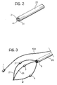
- Figures 2 and 3 show the probe portion of the device according to the invention; in practice this is the head comprising the electrodes 2 to 4 which are intended to be inserted into one of the heart chambers by catheterization so that the scanning electrode 1, which is also inserted in the corresponding chamber by catheterization, can be located.
- the probe portion carrying the electrodes 2 to 4 is shown in the contracted, insertion position ( Figure 2) and in the opened-out or unfolded position of use ( Figure 3) in which the electrodes have been brought to the spread-out position by respective support elements 21, 31, and 41 of known type made, for example, of a material with a shape memory.
- FIG 2 shows the unit used for catheterization.
- This unit comprises, basically, a sheath 20 which can be retracted onto the body of the insertion catheter (which is not shown in detail but is of known type) as shown in Figure 3 in order to achieve a dual effect of uncovering and releasing the elements 21, 31 and 41.
- the three electrodes 2, 3 and 4 open out so as to be arranged in a spread-out configuration; they can thus constitute, in accordance with the criteria described above, the three axes of a reference system usable to identify and/or to display externally the position of the lead 1.
- a further reference electrode G to which the potentials of the electrodes 2, 3 and 4 are in fact related, as is also that of the electrode 1, with regard to the determination of the potential established between the electrodes.
- this reference electrode is in fact identified by the earth or ground of the circuit.
- the position of the electrode 1 prefferably, it has been found preferable to arrange for the position of the electrode 1 to be detected by generating the respective signals in synchronism with the heart movement (deduced, for example, from an external electrocardiographic signal) so as to perform the detection in successive heart cycles, with the benefit of a substantially identical position of the heart muscle in the successive cycles.
- the necessary synchronization in order for the function of locating the electrode 1 to be performed at a predetermined stage (for example, the stage of maximum fullness, that is, the end of the diastole, or the stage of maximum emptiness, that is, the end of the systole) of the heart cycle can easily be performed by means of the unit 10.
Claims (11)
- Einrichtung zur Lokalisierung einer Elektrode (1), welche bei endokardialer Behandlung verwendet wird, die aufweist:weitere Elektrodenmittel (2 bis 4), welche zusammen im Herz mit der Elektrode (1) positioniert werden können, wobei die weiteren Elektrodenmittel (2 bis 4) dazu in der Lage sind, eine geometrische Anordnung einzunehmen, welche ein System von räumlichen Koordinaten vorgibt,Polarisationsmittel (13) zur Zufuhr jeweiliger elektrischer Signale an wenigstens eine der Elektroden (1) und der weiteren Elektrodenmittel (2 bis 4),Detektormittel (5 bis 8), welche mit der Elektrode (1) und den weiteren Elektrodenmitteln (2 bis 4) zur Detektion des Potentials verbunden sind, welches zwischen der Elektrode (1) und den weiteren Elektrodenmitteln (2 bis 4) als ein Ergebnis der Anwendung der elektrischen Signale aufgebaut ist, undMessmittel (9, 10, 14 bis 16) empfindlich für das Potential und dazu in der Lage auf der Basis des Potentials die Lage der Elektrode (1) relativ zu dem System räumlicher Koordinaten, welches durch die weiteren Elektrodenmittel (2 bis 4) vorgegeben wird, zu bestimmen, dadurch gekennzeichnet, dass die Polarisationsmittel so aufgebaut sind, dass sie die Elektrode (1) und die weiteren Elektrodenmittel (2 bis 4) auf jeweilige vorbestimmte Potentialniveaus bringen, um Potentialdifferenzen zwischen der Elektrode (1) und den weiteren Elektrodenmitteln (2 bis 4) zu erzeugen und ebenso zwischen den weiteren Elektrodenmitteln (2 bis 4), und dadurch, dass die Einrichtung wenigstens eine weitere Referenzelektrode (G) aufweist, zu welcher die Potentiale der Elektrode (1) und der weiteren Elektrodenmittel (2 bis 4) in Bezug stehen, bei der Bestimmung der Potentiale, die zwischen der Elektrode (1) und den weiteren Elektrodenmitteln (2 bis 4) bestehen, ebenso wie zwischen den weiteren Elektrodenmitteln (2 bis 4), wobei die relativen Positionen der Elektroden (1 bis 4) durch Variationen von vorbestimmten Potentialniveaus bestimmt werden.
- Vorrichtung nach Anspruch 1, dadurch gekennzeichnet, dass die weiteren Elektrodenmittel (2 bis 4) eine Vielzahl von Elektroden (2 bis 4) beinhalten, welche sich in verschiedenen Richtungen erstrecken können, so dass jede der Elektroden aus der Vielzahl (2 bis 4) wenigstens einen jeweiligen Bestandteil des geometrischen Referenzsystems kennzeichnet.
- Vorrichtung nach Anspruch 2, dadurch gekennzeichnet, dass die Vielzahl drei Elektroden (2 bis 4) beinhaltet.
- Vorrichtung nach irgendeinem der vorhergehenden Ansprüche, dadurch gekennzeichnet, dass die Polarisationsmittel (13) elektrische Signale als elektrische Signale der Intensität erzeugen, welche unterhalb der Herzmuskelstimulationsgrenze liegt.
- Vorrichtung nach irgendeinem der Ansprüche 1 bis 4, dadurch gekennzeichnet, dass die elektrischen Signale gepulste Signale sind.
- Vorrichtung nach Anspruch 5, dadurch gekennzeichnet, dass die Polarisationsmittel (13) wenigstens einen der Parameter variieren können, die durch die Pulsamplitude und die Pulsbreite gegeben sind.
- Vorrichtung nach irgendeinem der vorhergehenden Ansprüche, dadurch gekennzeichnet, dass die Elektrode (1) zugeordnete endokardiale Betriebsmittel aufweist, die aus einer Gruppe gewählt werden, die sich zusammensetzt aus:Ablationselektrodenoptische Fasern zur Endoskopie,optische Fasern zur oberflächigen Anwendung von Laserstrahlung,Einrichtungen zur Durchführung mikroskopischer, chirurgischer Eingriffe.
- Vorrichtung nach irgendeinem der vorhergehenden Ansprüche, dadurch gekennzeichnet, dass die weiteren Elektrodenmittel (2 bis 4) zugeordnete Rückhaltemittel (20) aufweisen, welche die weiteren Elektrodenmittel in einer kontrahierten Lage während der Einfügung in eine Herzkammer halten, wobei die Rückhaltemittel (20) wenigstens lokal lösbar von den weiteren Elektrodemitteln (2 bis 4) vorgesehen sind, um es den weiteren Elektrodenmitteln (2 bis 4) zu gestatten, sich gemäß der geometrischen Anordnung, welche das System von räumlichen Koordinaten vorgibt, zu öffnen.
- Vorrichtung nach Anspruch 8, dadurch gekennzeichnet, dass die Rückhaltemittel einen Mantel (20) umfassen, welcher die weiteren Elektrodenmittel (2 bis 4) in der zusammengezogenen Lage beschränkt, und welcher zurückgezogen werden kann, um es den weiteren Elektrodenmitteln (2 bis 4) zu gestatten, sich aufzuöffnen.
- Vorrichtung nach irgendeinem der Ansprüche 1 bis 7, dadurch gekennzeichnet, dass sie weitere positive Aufrichtungsmittel aufweist, die mit den weiteren Elektrodemitteln (2 bis 4) in Verbindung stehen, wobei die Aufrichtungsmittel dazu in der Lage sind, wahlweise aktiviert zu werden, um die weiteren Elektrodenmitteln (2 bis 4) zu der geometrischen Anordnung zu öffnen, welche das geometrische System von räumlichen Koordinaten vorgibt.
- Vorrichtung nach irgendeinem der vorhergehenden Ansprüche, dadurch gekennzeichnet, dass es weiter Mittel (10) zur Synchronisation mit einem externen elektrokardiographischen Signal aufweist, um die Lage der Elektrode (1) relativ zum System von räumlichen Koordinaten zu einer vorbestimmten Stufe von aufeinanderfolgenden Herzzyklen zu bestimmen.
Priority Applications (4)
| Application Number | Priority Date | Filing Date | Title |
|---|---|---|---|
| DE69920395T DE69920395T2 (de) | 1999-01-28 | 1999-01-28 | Vorrichtung zur Ortsbestimmung von endokardialen Elektroden |
| ES99830032T ES2227996T3 (es) | 1999-01-28 | 1999-01-28 | Dispositivo para localizar electrodos enodcardiacos. |
| EP99830032A EP1023870B1 (de) | 1999-01-28 | 1999-01-28 | Vorrichtung zur Ortsbestimmung von endokardialen Elektroden |
| US09/301,183 US6318375B1 (en) | 1999-01-28 | 1999-04-28 | Device for locating endocardial electrodes |
Applications Claiming Priority (1)
| Application Number | Priority Date | Filing Date | Title |
|---|---|---|---|
| EP99830032A EP1023870B1 (de) | 1999-01-28 | 1999-01-28 | Vorrichtung zur Ortsbestimmung von endokardialen Elektroden |
Publications (2)
| Publication Number | Publication Date |
|---|---|
| EP1023870A1 EP1023870A1 (de) | 2000-08-02 |
| EP1023870B1 true EP1023870B1 (de) | 2004-09-22 |
Family
ID=8243243
Family Applications (1)
| Application Number | Title | Priority Date | Filing Date |
|---|---|---|---|
| EP99830032A Expired - Lifetime EP1023870B1 (de) | 1999-01-28 | 1999-01-28 | Vorrichtung zur Ortsbestimmung von endokardialen Elektroden |
Country Status (4)
| Country | Link |
|---|---|
| US (1) | US6318375B1 (de) |
| EP (1) | EP1023870B1 (de) |
| DE (1) | DE69920395T2 (de) |
| ES (1) | ES2227996T3 (de) |
Families Citing this family (30)
| Publication number | Priority date | Publication date | Assignee | Title |
|---|---|---|---|---|
| WO2002089901A2 (en) * | 2001-05-03 | 2002-11-14 | Quetzal Biomedical, Inc. | Method and apparatus for determining spatial relation of multiple implantable electrodes |
| US20060173300A1 (en) * | 2005-01-11 | 2006-08-03 | Aga Medical Corp. | Open structure sizing device |
| US7908005B2 (en) | 2006-03-27 | 2011-03-15 | St. Jude Medical Ab | Medical system for monitoring and localization of electrode leads in the heart |
| US7515954B2 (en) * | 2006-06-13 | 2009-04-07 | Rhythmia Medical, Inc. | Non-contact cardiac mapping, including moving catheter and multi-beat integration |
| US7505810B2 (en) | 2006-06-13 | 2009-03-17 | Rhythmia Medical, Inc. | Non-contact cardiac mapping, including preprocessing |
| US7729752B2 (en) * | 2006-06-13 | 2010-06-01 | Rhythmia Medical, Inc. | Non-contact cardiac mapping, including resolution map |
| US20080190438A1 (en) * | 2007-02-08 | 2008-08-14 | Doron Harlev | Impedance registration and catheter tracking |
| US8103327B2 (en) | 2007-12-28 | 2012-01-24 | Rhythmia Medical, Inc. | Cardiac mapping catheter |
| US8538509B2 (en) | 2008-04-02 | 2013-09-17 | Rhythmia Medical, Inc. | Intracardiac tracking system |
| US8137343B2 (en) * | 2008-10-27 | 2012-03-20 | Rhythmia Medical, Inc. | Tracking system using field mapping |
| US9398862B2 (en) | 2009-04-23 | 2016-07-26 | Rhythmia Medical, Inc. | Multi-electrode mapping system |
| US8103338B2 (en) | 2009-05-08 | 2012-01-24 | Rhythmia Medical, Inc. | Impedance based anatomy generation |
| US8571647B2 (en) | 2009-05-08 | 2013-10-29 | Rhythmia Medical, Inc. | Impedance based anatomy generation |
| US9131869B2 (en) | 2010-05-11 | 2015-09-15 | Rhythmia Medical, Inc. | Tracking using field mapping |
| US9002442B2 (en) | 2011-01-13 | 2015-04-07 | Rhythmia Medical, Inc. | Beat alignment and selection for cardiac mapping |
| US8428700B2 (en) | 2011-01-13 | 2013-04-23 | Rhythmia Medical, Inc. | Electroanatomical mapping |
| JP6139518B2 (ja) | 2011-07-05 | 2017-05-31 | カーディオインサイト テクノロジーズ インコーポレイテッド | 心電図マッピングのための位置決め |
| US9375163B2 (en) | 2012-11-28 | 2016-06-28 | Biosense Webster (Israel) Ltd. | Location sensing using a local coordinate system |
| US9636032B2 (en) | 2013-05-06 | 2017-05-02 | Boston Scientific Scimed Inc. | Persistent display of nearest beat characteristics during real-time or play-back electrophysiology data visualization |
| JP6182665B2 (ja) | 2013-05-14 | 2017-08-16 | ボストン サイエンティフィック サイムド,インコーポレイテッドBoston Scientific Scimed,Inc. | ベクトル場を用いた電気生理学的マッピング中の活動パターンの表示及び特定のためのカテーテルシステム |
| WO2015057521A1 (en) | 2013-10-14 | 2015-04-23 | Boston Scientific Scimed, Inc. | High resolution cardiac mapping electrode array catheter |
| WO2015158789A1 (en) * | 2014-04-16 | 2015-10-22 | Alma Mater Studiorum - Università di Bologna | Heart valve prosthesis with integrated electronic circuit for measuring intravalvular electrical impedance, and system for monitoring functionality of the prosthesis |
| WO2015187386A1 (en) | 2014-06-03 | 2015-12-10 | Boston Scientific Scimed, Inc. | Electrode assembly having an atraumatic distal tip |
| WO2015187430A2 (en) | 2014-06-04 | 2015-12-10 | Boston Scientific Scimed, Inc. | Electrode assembly |
| US10758144B2 (en) | 2015-08-20 | 2020-09-01 | Boston Scientific Scimed Inc. | Flexible electrode for cardiac sensing and method for making |
| US10405766B2 (en) | 2015-09-26 | 2019-09-10 | Boston Scientific Scimed, Inc. | Method of exploring or mapping internal cardiac structures |
| EP3352662B1 (de) | 2015-09-26 | 2019-08-14 | Boston Scientific Scimed Inc. | Intrakardiale egm-signale zur schlaganpassung und -akzeptanz |
| EP3352648B1 (de) | 2015-09-26 | 2022-10-26 | Boston Scientific Scimed Inc. | Überwachung mit mehreren rhythmusvorlagen |
| EP3353753A1 (de) | 2015-09-26 | 2018-08-01 | Boston Scientific Scimed Inc. | Systeme und verfahren zur anatomischen schalenbearbeitung |
| US10973436B2 (en) | 2016-09-22 | 2021-04-13 | Walter Kusumoto | Pericardiocentesis needle guided by cardiac electrophysiology mapping |
Family Cites Families (10)
| Publication number | Priority date | Publication date | Assignee | Title |
|---|---|---|---|---|
| US5553611A (en) * | 1994-01-06 | 1996-09-10 | Endocardial Solutions, Inc. | Endocardial measurement method |
| EP0661948B1 (de) * | 1992-09-23 | 1997-11-19 | Endocardial Solutions, Inc. | Endokard-mapping system |
| US5297549A (en) * | 1992-09-23 | 1994-03-29 | Endocardial Therapeutics, Inc. | Endocardial mapping system |
| US5662108A (en) * | 1992-09-23 | 1997-09-02 | Endocardial Solutions, Inc. | Electrophysiology mapping system |
| US5722402A (en) * | 1994-10-11 | 1998-03-03 | Ep Technologies, Inc. | Systems and methods for guiding movable electrode elements within multiple-electrode structures |
| US5876336A (en) * | 1994-10-11 | 1999-03-02 | Ep Technologies, Inc. | Systems and methods for guiding movable electrode elements within multiple-electrode structure |
| US5752513A (en) * | 1995-06-07 | 1998-05-19 | Biosense, Inc. | Method and apparatus for determining position of object |
| SE9603314D0 (sv) * | 1996-09-12 | 1996-09-12 | Siemens Elema Ab | Förfarande och anordning för att bestämma läget hos en kateter inuti kroppen hos en patient |
| US5855592A (en) * | 1997-04-24 | 1999-01-05 | Ep Technologies, Inc. | Systems and methods for multi-site cardiac defibrillation using multiple electrode structures |
| US6014579A (en) * | 1997-07-21 | 2000-01-11 | Cardiac Pathways Corp. | Endocardial mapping catheter with movable electrode |
-
1999
- 1999-01-28 ES ES99830032T patent/ES2227996T3/es not_active Expired - Lifetime
- 1999-01-28 DE DE69920395T patent/DE69920395T2/de not_active Expired - Fee Related
- 1999-01-28 EP EP99830032A patent/EP1023870B1/de not_active Expired - Lifetime
- 1999-04-28 US US09/301,183 patent/US6318375B1/en not_active Expired - Fee Related
Also Published As
| Publication number | Publication date |
|---|---|
| ES2227996T3 (es) | 2005-04-01 |
| DE69920395T2 (de) | 2005-10-06 |
| US6318375B1 (en) | 2001-11-20 |
| DE69920395D1 (de) | 2004-10-28 |
| EP1023870A1 (de) | 2000-08-02 |
Similar Documents
| Publication | Publication Date | Title |
|---|---|---|
| EP1023870B1 (de) | Vorrichtung zur Ortsbestimmung von endokardialen Elektroden | |
| EP1240868B1 (de) | Vorrichtung zum Messen einer Mehrzahl von elektrischen Signalen vom Körper eines Patienten | |
| CA2189399C (en) | Catheter mapping system and method | |
| EP1125549B1 (de) | Katheter zur Erzeugung einer elektrischen Darstellung einer Herzkammer | |
| AU2013260655B2 (en) | Lasso catheter with tip electrode | |
| US6957101B2 (en) | Transient event mapping in the heart | |
| US7187964B2 (en) | Cardiac catheter imaging system | |
| EP2151209B1 (de) | Einzelachsensensoren auf flexiblem Träger | |
| KR100786547B1 (ko) | 심장의 전기적인 활동에 대한 빠른 맵핑 | |
| AU715925B2 (en) | Mapping catheter | |
| AU2013260702B2 (en) | Location sensing using a local coordinate system | |
| JP2001504010A (ja) | 体内領域における動作要素の位置決めおよび誘導のためのシステムおよび方法 | |
| US20080221423A1 (en) | Cardiac Catheter Imaging System | |
| EP4137051B1 (de) | Elektro-anatomische kartierung und beschriftung bei elektrophysiologischen verfahren |
Legal Events
| Date | Code | Title | Description |
|---|---|---|---|
| PUAI | Public reference made under article 153(3) epc to a published international application that has entered the european phase |
Free format text: ORIGINAL CODE: 0009012 |
|
| AK | Designated contracting states |
Kind code of ref document: A1 Designated state(s): DE ES FR GB IT NL |
|
| AX | Request for extension of the european patent |
Free format text: AL;LT;LV;MK;RO;SI |
|
| 17P | Request for examination filed |
Effective date: 20010102 |
|
| AKX | Designation fees paid |
Free format text: DE ES FR GB IT NL |
|
| 17Q | First examination report despatched |
Effective date: 20030828 |
|
| GRAP | Despatch of communication of intention to grant a patent |
Free format text: ORIGINAL CODE: EPIDOSNIGR1 |
|
| GRAS | Grant fee paid |
Free format text: ORIGINAL CODE: EPIDOSNIGR3 |
|
| RIN1 | Information on inventor provided before grant (corrected) |
Inventor name: MARCELLI, EMANUELA Inventor name: VALLANA, FRANCO Inventor name: GAGGINI, GUIDO Inventor name: GARBEROGLIO, BRUNO Inventor name: PLICCHI, GIANNI |
|
| GRAA | (expected) grant |
Free format text: ORIGINAL CODE: 0009210 |
|
| AK | Designated contracting states |
Kind code of ref document: B1 Designated state(s): DE ES FR GB IT NL |
|
| REG | Reference to a national code |
Ref country code: GB Ref legal event code: FG4D |
|
| REF | Corresponds to: |
Ref document number: 69920395 Country of ref document: DE Date of ref document: 20041028 Kind code of ref document: P |
|
| REG | Reference to a national code |
Ref country code: ES Ref legal event code: FG2A Ref document number: 2227996 Country of ref document: ES Kind code of ref document: T3 |
|
| PLBE | No opposition filed within time limit |
Free format text: ORIGINAL CODE: 0009261 |
|
| STAA | Information on the status of an ep patent application or granted ep patent |
Free format text: STATUS: NO OPPOSITION FILED WITHIN TIME LIMIT |
|
| RAP4 | Party data changed (patent owner data changed or rights of a patent transferred) |
Owner name: MINISTERO DELL' UNIVERSITA' E DELLA RICERCASCIENTI |
|
| ET | Fr: translation filed | ||
| 26N | No opposition filed |
Effective date: 20050623 |
|
| PGFP | Annual fee paid to national office [announced via postgrant information from national office to epo] |
Ref country code: NL Payment date: 20060103 Year of fee payment: 8 |
|
| PGFP | Annual fee paid to national office [announced via postgrant information from national office to epo] |
Ref country code: FR Payment date: 20060110 Year of fee payment: 8 |
|
| PGFP | Annual fee paid to national office [announced via postgrant information from national office to epo] |
Ref country code: IT Payment date: 20060131 Year of fee payment: 8 |
|
| PGFP | Annual fee paid to national office [announced via postgrant information from national office to epo] |
Ref country code: DE Payment date: 20060209 Year of fee payment: 8 |
|
| PGFP | Annual fee paid to national office [announced via postgrant information from national office to epo] |
Ref country code: ES Payment date: 20060215 Year of fee payment: 8 |
|
| PG25 | Lapsed in a contracting state [announced via postgrant information from national office to epo] |
Ref country code: DE Free format text: LAPSE BECAUSE OF NON-PAYMENT OF DUE FEES Effective date: 20070801 |
|
| GBPC | Gb: european patent ceased through non-payment of renewal fee |
Effective date: 20070128 |
|
| NLV4 | Nl: lapsed or anulled due to non-payment of the annual fee |
Effective date: 20070801 |
|
| REG | Reference to a national code |
Ref country code: FR Ref legal event code: ST Effective date: 20070930 |
|
| PG25 | Lapsed in a contracting state [announced via postgrant information from national office to epo] |
Ref country code: GB Free format text: LAPSE BECAUSE OF NON-PAYMENT OF DUE FEES Effective date: 20070128 |
|
| PG25 | Lapsed in a contracting state [announced via postgrant information from national office to epo] |
Ref country code: NL Free format text: LAPSE BECAUSE OF NON-PAYMENT OF DUE FEES Effective date: 20070801 |
|
| REG | Reference to a national code |
Ref country code: ES Ref legal event code: FD2A Effective date: 20070129 |
|
| PG25 | Lapsed in a contracting state [announced via postgrant information from national office to epo] |
Ref country code: FR Free format text: LAPSE BECAUSE OF NON-PAYMENT OF DUE FEES Effective date: 20070131 |
|
| PG25 | Lapsed in a contracting state [announced via postgrant information from national office to epo] |
Ref country code: ES Free format text: LAPSE BECAUSE OF NON-PAYMENT OF DUE FEES Effective date: 20070129 |
|
| PGFP | Annual fee paid to national office [announced via postgrant information from national office to epo] |
Ref country code: GB Payment date: 20060125 Year of fee payment: 8 |
|
| PG25 | Lapsed in a contracting state [announced via postgrant information from national office to epo] |
Ref country code: IT Free format text: LAPSE BECAUSE OF NON-PAYMENT OF DUE FEES Effective date: 20070128 |