EP1023823A2 - Landwirtschaftliche Verteilmaschine - Google Patents
Landwirtschaftliche Verteilmaschine Download PDFInfo
- Publication number
- EP1023823A2 EP1023823A2 EP00100766A EP00100766A EP1023823A2 EP 1023823 A2 EP1023823 A2 EP 1023823A2 EP 00100766 A EP00100766 A EP 00100766A EP 00100766 A EP00100766 A EP 00100766A EP 1023823 A2 EP1023823 A2 EP 1023823A2
- Authority
- EP
- European Patent Office
- Prior art keywords
- line
- lines
- transmission
- distributor according
- recess
- Prior art date
- Legal status (The legal status is an assumption and is not a legal conclusion. Google has not performed a legal analysis and makes no representation as to the accuracy of the status listed.)
- Granted
Links
Images



Classifications
-
- A—HUMAN NECESSITIES
- A01—AGRICULTURE; FORESTRY; ANIMAL HUSBANDRY; HUNTING; TRAPPING; FISHING
- A01C—PLANTING; SOWING; FERTILISING
- A01C7/00—Sowing
- A01C7/08—Broadcast seeders; Seeders depositing seeds in rows
- A01C7/10—Devices for adjusting the seed-box ; Regulation of machines for depositing quantities at intervals
- A01C7/102—Regulating or controlling the seed rate
- A01C7/105—Seed sensors
-
- A—HUMAN NECESSITIES
- A01—AGRICULTURE; FORESTRY; ANIMAL HUSBANDRY; HUNTING; TRAPPING; FISHING
- A01C—PLANTING; SOWING; FERTILISING
- A01C7/00—Sowing
- A01C7/20—Parts of seeders for conducting and depositing seed
- A01C7/206—Seed pipes
Definitions
- the invention relates to an agricultural distributor according to the preamble of claim 1.
- Such agricultural spreaders are in the Practice known in many ways. With these machines various functions are monitored by sensors or actuated by servomotors. These sensors and actuators are by means of transmission lines with tax evaluation and Control devices connected. These transmission lines are laid along frame parts, lines etc. and attached by means of cords, wires, cable ties etc.
- the invention has for its object a protected Propose routing of transmission lines.
- the Transmission lines at least partially within the pneumatically acted lines are arranged.
- the transmission lines at least in the areas in which they are usually pneumatically applied lines laid outside of these are arranged, protected and can not be damaged become.
- the laying and assembly of the transmission lines much simplified. It is also conceivable the transmission lines within the cavities of frame tubes etc. to arrange.
- the transmission lines are through the vacuum lines to the separating elements led in progress.
- a simple fastening and sealing can be done by the Achieve features of claim 4.
- a secure arrangement of the transmission line in the area of Transition from the inside to the outside of the vacuum line is achieved in that by means of the bandage Transmission line on the outside of the vacuum line and is thus attached to the suction line.
- the connecting piece for the pneumatically acted lines on their the lines assigned side each to the cross section of the transmission line have adapted recess, and that the Transmission lines laid in the cutouts are.
- the pneumatic line on the connecting piece to ensure it is provided that the recess at least around the measure of the diameter of the transmission line over the slide-on area of the pneumatically actuated Line extends.
- a simple arrangement of the recess on the connecting piece can be achieved in that the connecting piece for the pneumatically loaded lines are designed as adapters are, and that the recess in each case in the adapters is arranged.
- the agricultural trained as a precision seeder Distributor has the frame 1, on the precision sowing units 2 and a fertilizer reservoir 3 are arranged. Fertilizer coulters 4 are also arranged on the frame 1, which the material in the fertilizer reservoir 3 is supplied in adjustable amounts. Furthermore is on the frame 1, a vacuum blower 5 arranged, which a Has suction connection housing 7 with connecting piece 8. On these connecting pieces 8 are to the separating organs 9 of the precision seed drill units 2 leading suction hoses 10 connected. Furthermore, each precision sowing unit is 2 a sensor assigned to a monitoring device 11. The from the sensors to the evaluation device of the monitoring device 11 leading transmission lines 12 are within the pneumatically actuated lines 10 are arranged. Here, the transmission lines 12 are through in the walls 13 of the lines 12 drilled holes 14 in the Line 12 introduced.
- Adapter 21 trained connecting piece arranged on the blower nozzle 20 of the suction fan 17 . Furthermore is on the respective reservoir 22 of the precision sowing units 19 also designed as an adapter 21 Connection piece arranged on the intermediate piece 23. Between the two adapters 21 is on the slide-on area 24 pneumatically actuated line arranged. At the end of the Intermediate piece 23, which on the reservoir 22 of the Precision sowing unit 19 is arranged to the Suction kidney of line 18 leading the separation unit arranged.
- the transmission line 25 is arranged in the pneumatically acted line 16, which on the Slide-on areas 24 of the connecting piece 21 is arranged.
- This transmission line 25 is installed on the line 16 before Adapter 21 inserted into this line 16.
- the in Fig.5 to 7 shown adapter 21 pushed on and by suitable fasteners attached.
- the adapter 21, the the connecting pieces for the pneumatically actuated lines 16 form, have on their assigned to the lines 16 One side each to the cross section of the transmission line 25 adapted recess 26.
- This recess 26 is designed as a groove and at its base 27 circular arc designed.
- the recess 26 extends around the dimension A, which corresponds to the diameter D of the transmission line 25 corresponds via the slide-on area 25 of the pneumatic acted upon line 16 as shown in FIGS. 5 and 6.
- the line 16 with the transmission line 25 on the trained as an adapter 21 Slide on the connecting piece, the transmission line 25 and the recess 26 so arranged to each other or be aligned so that the transmission line 25 is located in the recess 26, so that the transmission line 25 laid in the recesses 26 is. It is also possible that after the introduction the transmission line 25 into line 16, line 16 on the slide-on area 24 of the adapter 21 Pushed connecting piece and there by means of hose clamps is clamped before the adapter 21 on the nozzle 20th the blower 16 and on the connecting piece of the intermediate piece 23, which is attached to the reservoir 22, arranged become. In this way, an advantageous pre-assembly of Transmission line 25, adapter 21 and line 16 take place.
Landscapes
- Life Sciences & Earth Sciences (AREA)
- Soil Sciences (AREA)
- Environmental Sciences (AREA)
- Catching Or Destruction (AREA)
- Sowing (AREA)
Abstract
Description
- Fig.1
- eine als Einzelkornsämaschine ausgebildete landwirtschaftliche Verteilmaschine in Prinzipdarstellung,
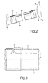
- Fig.2
- eine Unterdruckleitung mit darin verlegter Übertragungsleitung in Teilschnitt und in vergrößertem Maßstab,
- Fig.3
- einen Teilbereich der Übertragungsleitung in der Unterdruckleitung, im Bereich der Durchführung durch die Wandung der Unterdruckleitung mit darüber angeordneter Fixierungsbandage im Teilschnitt und in Prinzipdarstellung,
- Fig.4
- die Anordnung der Übertragungsleitung in der Unterdruckleitung in Prinzipdarstellung,
- Fig.5
- den als Anschlußstutzen ausgebildeten Adapter mit Aussparung in der Draufsicht,
- Fig.6
- den Adapter im Schnitt VI-VI und
- Fig.7
- den Adapter in der Ansicht VII-VII.
Claims (9)
- Landwirtschaftliche Verteilmaschine mit pneumatisch beaufschlagten Leitungen und Übertragungsleitungen aufweisenden Überwachungseinrichtungen, dadurch gekennzeichnet, daß die Übertragungsleitungen (12, 25) zumindest teilweise innerhalb der pneumatisch beaufschlagten Leitungen (10, 16) angeordnet sind.
- Verteilmaschine nach Anspruch 1, dadurch gekennzeichnet, daß die Übertragungsleitungen (12) durch in den Wandungen (13) der Leitungen (10) angebrachten Bohrungen (14) in die Leitungen (10) eingebracht sind.
- Verteilmaschine nach Anspruch 1, wobei die Verteilmaschine als Einzelkornsämaschine ausgebildet ist und von einem Sauggebläse (5) zu Vereinzelungsorganen (9) führenden Unterdruckleitungen (10) aufweist, dadurch gekennzeichnet, daß die Übertragungsleitungen (12) durch die Unterdruckleitung (10) bis zu den Vereinzelungsorganen (9) verlaufend geführt sind.
- Verteilmaschine nach einem oder mehreren der vorstehenden Ansprüche, dadurch gekennzeichnet, daß zum Durchführen der Übertragungsleitung (12) durch die Wandung (13) der Unterdruckleitung (10) jeweils ein dem Durchmesser der Übertragungsleitung (12) entsprechender Durchbruch (14) in der Leitung (12) angebracht ist, daß zum Fixieren der Übertragungsleitung (12) in der Bohrung (14) und an der Leitung (10) eine, vorzugsweise aus einem Schrumpfschlauch bestehende Fixierungsbandage (15) auf der Leitung (10) angeordnet ist, daß die Übertragungsleitung (12) zwischen der Außenwand der Leitung (10) und der Bandage (15) sich befindet.
- Verteilmaschine nach einem oder mehreren der vorstehenden Ansprüche, dadurch gekennzeichnet, daß mittels der Bandage (15) die Übertragungsleitung (12) auf der Außenseite der Unterdruckleitung (10) und somit an der Saugleitung (10) befestigt ist.
- Verteilmaschine nach Anspruch 1, dadurch gekennzeichnet, daß die Anschlußstutzen (21) für die pneumatisch beaufschlagten Leitungen (16) auf ihrer den Leitungen (16) zugeordneten Seite jeweils eine an den Querschnitt der Übertragungsleitungen (25) angepaßte Aussparung (26) aufweisen, daß die Übertragungsleitungen (25) in den Aussparungen (26) verlegt angeordnet sind.
- Verteilmaschine nach einem oder mehreren der vorstehenden Ansprüche, dadurch gekennzeichnet, daß die Aussparung (26) als Nut und an ihrem Grund (27) kreisbogenförmig ausgebildet ist.
- Verteilmaschine nach einem oder mehreren der vorstehenden Ansprüche, dadurch gekennzeichnet, daß die Aussparung (26) sich zumindest um das Maß (A), welches dem Durchmesser (D) der Übertragungsleitung (25) entspricht, über den Aufschubbereich (24) der pneumatisch beaufschlagten Leitung (16) hinauserstreckt.
- Verteilmaschine nach einem oder mehreren der vorstehenden Ansprüche, dadurch gekennzeichnet, daß die Anschlußstutzen (21) für die pneumatisch beaufschlagten Leitungen (16) als Adapter ausgebildet sind, daß die Aussparung (26) jeweils in den Adaptern (22) angeordnet ist.
Applications Claiming Priority (4)
| Application Number | Priority Date | Filing Date | Title |
|---|---|---|---|
| DE19902272 | 1999-01-21 | ||
| DE19902272 | 1999-01-21 | ||
| DE19961703A DE19961703A1 (de) | 1999-01-21 | 1999-12-21 | Landwirtschaftliche Verteilmaschine |
| DE19961703 | 1999-12-21 |
Publications (3)
| Publication Number | Publication Date |
|---|---|
| EP1023823A2 true EP1023823A2 (de) | 2000-08-02 |
| EP1023823A3 EP1023823A3 (de) | 2000-08-23 |
| EP1023823B1 EP1023823B1 (de) | 2003-07-30 |
Family
ID=26051417
Family Applications (1)
| Application Number | Title | Priority Date | Filing Date |
|---|---|---|---|
| EP20000100766 Expired - Lifetime EP1023823B1 (de) | 1999-01-21 | 2000-01-15 | Landwirtschaftliche Verteilmaschine |
Country Status (2)
| Country | Link |
|---|---|
| EP (1) | EP1023823B1 (de) |
| DK (1) | DK1023823T3 (de) |
Cited By (3)
| Publication number | Priority date | Publication date | Assignee | Title |
|---|---|---|---|---|
| DE102010017205A1 (de) | 2010-06-02 | 2011-12-08 | Amazonen-Werke H. Dreyer Gmbh & Co. Kg | Landwirtschaftliche Verteilmaschine |
| US9320192B2 (en) | 2013-11-12 | 2016-04-26 | Dickey-John Corporation | Synchronization of a twin row planting system |
| CN108848782A (zh) * | 2018-07-16 | 2018-11-23 | 山东理工大学 | 一种基于机器视觉的精量播种自动监测及补种装置 |
Families Citing this family (1)
| Publication number | Priority date | Publication date | Assignee | Title |
|---|---|---|---|---|
| CA3121512C (en) * | 2020-07-14 | 2024-03-19 | Greenvalley Equipment (2009) Inc. | Collection device for meter calibration of air seeder tanks |
Family Cites Families (5)
| Publication number | Priority date | Publication date | Assignee | Title |
|---|---|---|---|---|
| US3422776A (en) * | 1967-01-04 | 1969-01-21 | Lester Gregory Jr | Monitor means and counter mechanism for use with seed planters and the like |
| US4159064A (en) * | 1977-08-03 | 1979-06-26 | Dickey-John Corporation | Seed planter monitor |
| NL7800713A (nl) * | 1978-01-20 | 1979-07-24 | Patent Concern Nv | Landbouwmachine of dergelijke inrichting. |
| FR2423963A1 (fr) * | 1978-04-24 | 1979-11-23 | Mezogazdasagi Gepkiserleti Int | Dispositif de controle de distribution de semences, notamment pour les semoirs mecaniques a nombre eleve de rayonneurs |
| DE3803264A1 (de) * | 1988-02-04 | 1989-08-17 | Amazonen Werke Dreyer H | Landwirtschaftliche kombinationssaemaschine |
-
2000
- 2000-01-15 DK DK00100766T patent/DK1023823T3/da active
- 2000-01-15 EP EP20000100766 patent/EP1023823B1/de not_active Expired - Lifetime
Non-Patent Citations (1)
| Title |
|---|
| None |
Cited By (3)
| Publication number | Priority date | Publication date | Assignee | Title |
|---|---|---|---|---|
| DE102010017205A1 (de) | 2010-06-02 | 2011-12-08 | Amazonen-Werke H. Dreyer Gmbh & Co. Kg | Landwirtschaftliche Verteilmaschine |
| US9320192B2 (en) | 2013-11-12 | 2016-04-26 | Dickey-John Corporation | Synchronization of a twin row planting system |
| CN108848782A (zh) * | 2018-07-16 | 2018-11-23 | 山东理工大学 | 一种基于机器视觉的精量播种自动监测及补种装置 |
Also Published As
| Publication number | Publication date |
|---|---|
| EP1023823B1 (de) | 2003-07-30 |
| DK1023823T3 (da) | 2003-08-18 |
| EP1023823A3 (de) | 2000-08-23 |
Similar Documents
| Publication | Publication Date | Title |
|---|---|---|
| EP1164827B1 (de) | Pneumatischer verteiler | |
| DE19522229C2 (de) | Sävorrichtung mit modularem Dosiergerät | |
| EP1135980B1 (de) | Sämaschine und pneumatisches Reduzierelement | |
| DE102010002200A1 (de) | Kalibriervorrichtung | |
| EP1348326A1 (de) | Saemaschine und pneumatische Kupplung | |
| DE102008037782A1 (de) | Pneumatische Sämaschine | |
| DE102008050735A1 (de) | Pneumatische Direktsämaschine | |
| DE3530514C2 (de) | ||
| EP3108171B1 (de) | Schlauchstecksystem einer landwirtschaftlichen verteilmaschine | |
| DE102011053745A1 (de) | Mehrfachdüsenkörper für eine landwirtschaftliche Feldspritze | |
| EP1023823B1 (de) | Landwirtschaftliche Verteilmaschine | |
| DE102015105790A1 (de) | Landwirtschaftliche Einzelkornsämaschine | |
| DE60315559T2 (de) | Vorrichtung zum Melken eines Tieres | |
| DE19961703A1 (de) | Landwirtschaftliche Verteilmaschine | |
| EP0956756B1 (de) | Kombiniertes Normal- und Feinsärad | |
| DE102008016107A1 (de) | Verteiler für eine Verteilmaschine | |
| DE102007047689A1 (de) | Verteilerkopf | |
| DE102004008052B4 (de) | Vorrichtung zum optischen Zählen kleiner Körperchen | |
| DE68916314T2 (de) | Düngerstreuer. | |
| DE102005008290A1 (de) | Pneumatische Verteilmaschine für Saatgut, Dünger oder dergleichen | |
| DE19538626A1 (de) | Landwirtschaftliche Verteilmaschine | |
| DE3627801A1 (de) | Drillmaschine | |
| DE4309462C2 (de) | Säschar | |
| EP1621060B1 (de) | Pneumatische Einzelkornsämaschine | |
| EP3818804B1 (de) | Versorgungseinrichtung für eine kornvereinzelungsvorrichtung |
Legal Events
| Date | Code | Title | Description |
|---|---|---|---|
| PUAI | Public reference made under article 153(3) epc to a published international application that has entered the european phase |
Free format text: ORIGINAL CODE: 0009012 |
|
| PUAL | Search report despatched |
Free format text: ORIGINAL CODE: 0009013 |
|
| AK | Designated contracting states |
Kind code of ref document: A2 Designated state(s): DE DK FR IT NL |
|
| AX | Request for extension of the european patent |
Free format text: AL;LT;LV;MK;RO;SI |
|
| AK | Designated contracting states |
Kind code of ref document: A3 Designated state(s): DE DK FR IT NL |
|
| AX | Request for extension of the european patent |
Free format text: AL;LT;LV;MK;RO;SI |
|
| RIC1 | Information provided on ipc code assigned before grant |
Free format text: 7A 01C 7/20 A, 7A 01C 7/10 B |
|
| 17P | Request for examination filed |
Effective date: 20010113 |
|
| AKX | Designation fees paid |
Free format text: DE DK FR IT NL |
|
| 17Q | First examination report despatched |
Effective date: 20021017 |
|
| GRAH | Despatch of communication of intention to grant a patent |
Free format text: ORIGINAL CODE: EPIDOS IGRA |
|
| GRAH | Despatch of communication of intention to grant a patent |
Free format text: ORIGINAL CODE: EPIDOS IGRA |
|
| GRAA | (expected) grant |
Free format text: ORIGINAL CODE: 0009210 |
|
| AK | Designated contracting states |
Designated state(s): DE DK FR IT NL |
|
| PG25 | Lapsed in a contracting state [announced via postgrant information from national office to epo] |
Ref country code: IT Free format text: LAPSE BECAUSE OF FAILURE TO SUBMIT A TRANSLATION OF THE DESCRIPTION OR TO PAY THE FEE WITHIN THE PRESCRIBED TIME-LIMIT;WARNING: LAPSES OF ITALIAN PATENTS WITH EFFECTIVE DATE BEFORE 2007 MAY HAVE OCCURRED AT ANY TIME BEFORE 2007. THE CORRECT EFFECTIVE DATE MAY BE DIFFERENT FROM THE ONE RECORDED. Effective date: 20030730 Ref country code: NL Free format text: LAPSE BECAUSE OF FAILURE TO SUBMIT A TRANSLATION OF THE DESCRIPTION OR TO PAY THE FEE WITHIN THE PRESCRIBED TIME-LIMIT Effective date: 20030730 |
|
| REG | Reference to a national code |
Ref country code: DK Ref legal event code: T3 |
|
| REF | Corresponds to: |
Ref document number: 50003051 Country of ref document: DE Date of ref document: 20030904 Kind code of ref document: P |
|
| NLV1 | Nl: lapsed or annulled due to failure to fulfill the requirements of art. 29p and 29m of the patents act | ||
| ET | Fr: translation filed | ||
| PLBE | No opposition filed within time limit |
Free format text: ORIGINAL CODE: 0009261 |
|
| STAA | Information on the status of an ep patent application or granted ep patent |
Free format text: STATUS: NO OPPOSITION FILED WITHIN TIME LIMIT |
|
| 26N | No opposition filed |
Effective date: 20040504 |
|
| PGFP | Annual fee paid to national office [announced via postgrant information from national office to epo] |
Ref country code: DK Payment date: 20090123 Year of fee payment: 10 |
|
| REG | Reference to a national code |
Ref country code: DK Ref legal event code: EBP |
|
| PG25 | Lapsed in a contracting state [announced via postgrant information from national office to epo] |
Ref country code: DK Free format text: LAPSE BECAUSE OF NON-PAYMENT OF DUE FEES Effective date: 20100131 |
|
| REG | Reference to a national code |
Ref country code: FR Ref legal event code: PLFP Year of fee payment: 17 |
|
| REG | Reference to a national code |
Ref country code: FR Ref legal event code: PLFP Year of fee payment: 18 |
|
| PGFP | Annual fee paid to national office [announced via postgrant information from national office to epo] |
Ref country code: FR Payment date: 20161215 Year of fee payment: 18 |
|
| PGFP | Annual fee paid to national office [announced via postgrant information from national office to epo] |
Ref country code: DE Payment date: 20180103 Year of fee payment: 19 |
|
| PG25 | Lapsed in a contracting state [announced via postgrant information from national office to epo] |
Ref country code: FR Free format text: LAPSE BECAUSE OF NON-PAYMENT OF DUE FEES Effective date: 20180131 |
|
| REG | Reference to a national code |
Ref country code: FR Ref legal event code: ST Effective date: 20180928 |
|
| REG | Reference to a national code |
Ref country code: DE Ref legal event code: R119 Ref document number: 50003051 Country of ref document: DE |
|
| PG25 | Lapsed in a contracting state [announced via postgrant information from national office to epo] |
Ref country code: DE Free format text: LAPSE BECAUSE OF NON-PAYMENT OF DUE FEES Effective date: 20190801 |