EP1023518B1 - Machine for applying parts to material - Google Patents
Machine for applying parts to material Download PDFInfo
- Publication number
- EP1023518B1 EP1023518B1 EP98951567A EP98951567A EP1023518B1 EP 1023518 B1 EP1023518 B1 EP 1023518B1 EP 98951567 A EP98951567 A EP 98951567A EP 98951567 A EP98951567 A EP 98951567A EP 1023518 B1 EP1023518 B1 EP 1023518B1
- Authority
- EP
- European Patent Office
- Prior art keywords
- parts
- machine
- combination according
- transfer
- transfer tracks
- Prior art date
- Legal status (The legal status is an assumption and is not a legal conclusion. Google has not performed a legal analysis and makes no representation as to the accuracy of the status listed.)
- Expired - Lifetime
Links
- 239000000463 material Substances 0.000 title description 3
- 238000007664 blowing Methods 0.000 claims description 5
- 239000005022 packaging material Substances 0.000 claims description 4
- 238000007599 discharging Methods 0.000 claims description 2
- 230000014759 maintenance of location Effects 0.000 claims 2
- 238000004806 packaging method and process Methods 0.000 description 9
- 239000004033 plastic Substances 0.000 description 6
- 229920003023 plastic Polymers 0.000 description 6
- 238000004519 manufacturing process Methods 0.000 description 3
- 230000008859 change Effects 0.000 description 2
- 238000000034 method Methods 0.000 description 2
- 230000008569 process Effects 0.000 description 2
- 238000003466 welding Methods 0.000 description 2
- 241000282472 Canis lupus familiaris Species 0.000 description 1
- 230000008901 benefit Effects 0.000 description 1
- 238000011109 contamination Methods 0.000 description 1
- 230000009977 dual effect Effects 0.000 description 1
- 239000007788 liquid Substances 0.000 description 1
- 230000007246 mechanism Effects 0.000 description 1
- 230000004044 response Effects 0.000 description 1
Images


Classifications
-
- B—PERFORMING OPERATIONS; TRANSPORTING
- B65—CONVEYING; PACKING; STORING; HANDLING THIN OR FILAMENTARY MATERIAL
- B65B—MACHINES, APPARATUS OR DEVICES FOR, OR METHODS OF, PACKAGING ARTICLES OR MATERIALS; UNPACKING
- B65B61/00—Auxiliary devices, not otherwise provided for, for operating on sheets, blanks, webs, binding material, containers or packages
- B65B61/18—Auxiliary devices, not otherwise provided for, for operating on sheets, blanks, webs, binding material, containers or packages for making package-opening or unpacking elements
- B65B61/186—Auxiliary devices, not otherwise provided for, for operating on sheets, blanks, webs, binding material, containers or packages for making package-opening or unpacking elements by applying or incorporating rigid fittings, e.g. discharge spouts
Definitions
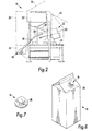
- a fixed mounting block 54 ( Figure 5) is secured to the base 42, and includes a passage 56 formed therethrough for receiving and confining the end portion of the fixed track 34.
- a pair of air manifold blocks 58 are secured to the base 42 on opposite sides of the fixed mounting block 54 and abut against the oppositely disposed side walls of the block 54.
- An air passage 60 is formed through the centre of each block 58, parallel to the track mounting passage 56 in the block 54.
- a source 62 of compressed air is connected by a line 64 to each air passage 60. Suitable valves are included in an air valve pack 66 ( Figure 3) mounted in the housing 20.
Landscapes
- Engineering & Computer Science (AREA)
- Mechanical Engineering (AREA)
- Feeding Of Articles To Conveyors (AREA)
- Auxiliary Devices For And Details Of Packaging Control (AREA)
Description
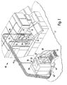
a machine including parts-applying means for applying parts to packaging material on said machine,
a parts-supplying device including parts-supplying means and free-standing relative to said machine, and
transferring means extending from said device to said machine and serving to transfer said parts from said device to said machine,
characterized in that said transferring means comprises pneumatic parts-conveying means and in that said parts-conveying means is communicable with a source of compressed gas for blowing said parts along said parts-conveying means.
The device includes a parts handling bowl which, via centrifugal force created by rotary motion, urges the pour spout fitments toward and through suitable orienting devices to orient the fitments and feed them to a track for transfer to a slide shuttle assembly co-operable with programmable cylinder or servo-driven means for further transfer via the multiple plastics tubes to placement devices which assemble the fitments in any suitable manner onto one or more sets of dual in-line cartons being indexed along conveyors of the packaging machine.
Claims (10)
- In combination,
a machine (10) including parts-applying means (74) for applying parts (18) to packaging material (12) on said machine (10),
a parts-supplying device (16) including parts-supplying means (30) and free-standing relative to said machine (10), and
transferring means (14) extending from said device (16) to said machine (10) and serving to transfer said parts (18) from said device (16) to said machine (10),
characterized in that said transferring means (14) comprises pneumatic parts-conveying means (14) and in that said parts-conveying means (14) is communicable with a source (62) of compressed gas for blowing said parts (18) along said parts-conveying means (14). - A combination according to claim 1, and further comprising
a second machine (10) including second parts-applying means (74) for applying other parts (18) to packaging material (12) on said second machine (10), and
second transferring means (14) extending from said device (16) to said second machine (10) and serving to transfer said other parts (18) from said device (16) to said second machine (10),
said device (16) being free-standing relative to said second machine (10). - A combination according to claim 2, wherein said second transferring means (14) comprises second pneumatic parts-conveying means (14) communicable with said source (62) for blowing said other parts (18) along the second parts-conveying means (14).
- A combination according to any preceding claim, wherein the or each machine (10) comprises a plurality of materials-conveying means arranged to advance respective packaging materials (12) and wherein the or each parts-applying means (74) comprises a plurality of parts applicators (74) associated with the respective materials-conveying means of the machine (10).
- A combination according to any preceding claim, wherein the pneumatic parts-conveying means (14) comprises a plurality of transfer tracks (14) and said device (16) further includes a discharge track (34) for discharging oriented parts (18) and a distributor (40) arranged to receive oriented parts (18) from said discharge track (34) and to distribute them among said transfer tracks (14).
- A combination according to claim 5, wherein said distributor (40) comprises a side shuttle (48).
- A combination according to claim 6, wherein said distributor (40) further comprises fixed passage means (60) to which said source (62) supples said compressed gas and at times directs said gas into selected ones of said transfer tracks (14), retention means (46) attaching said transfer tracks (14) to said slide shuttle (48), and programmed drive means (50) for laterally moving said slide shuttle (48) and thereby bringing entry ends of said transfer tracks (14) selectively into and out of alignment with said passage means (60) to cause parts (18) to be blown through said transfer tracks (14) by said compressed gas to the parts-applying means (74).
- A combination according to claim 7, wherein said fixed passage means (60) comprises a plurality of fixed passages (60) and wherein a plurality of said transfer tracks (14) and said retention means (46) are selectively alternately moved by said programmed drive means (50) into alignment with each of said fixed passages (60).
- A combination according to any one of claims 5 to 8 and further comprising parts-detecting means (72) at the respective transfer tracks (14) at the or each machine (10) and arranged to signal said programmed drive means (46) when any of respective portions of the transfer tracks (14) at the machine (10) are full of parts (18).
- A combination according to any preceding claim, wherein said device (16) further comprises a clean-out track (14') to serve in cleaning-out said parts (18) from said device (16).
Priority Applications (1)
| Application Number | Priority Date | Filing Date | Title |
|---|---|---|---|
| EP02025988A EP1293435A1 (en) | 1997-10-24 | 1998-10-26 | Machine for applying parts to material |
Applications Claiming Priority (3)
| Application Number | Priority Date | Filing Date | Title |
|---|---|---|---|
| US6309697P | 1997-10-24 | 1997-10-24 | |
| US63096P | 1997-10-24 | ||
| PCT/GB1998/003224 WO1999029152A2 (en) | 1997-10-24 | 1998-10-26 | Machine for applying parts to articles |
Related Child Applications (1)
| Application Number | Title | Priority Date | Filing Date |
|---|---|---|---|
| EP02025988A Division EP1293435A1 (en) | 1997-10-24 | 1998-10-26 | Machine for applying parts to material |
Publications (2)
| Publication Number | Publication Date |
|---|---|
| EP1023518A2 EP1023518A2 (en) | 2000-08-02 |
| EP1023518B1 true EP1023518B1 (en) | 2003-08-06 |
Family
ID=22046908
Family Applications (1)
| Application Number | Title | Priority Date | Filing Date |
|---|---|---|---|
| EP98951567A Expired - Lifetime EP1023518B1 (en) | 1997-10-24 | 1998-10-26 | Machine for applying parts to material |
Country Status (5)
| Country | Link |
|---|---|
| US (2) | US6527688B1 (en) |
| EP (1) | EP1023518B1 (en) |
| JP (1) | JP2001525296A (en) |
| DE (1) | DE69817002T2 (en) |
| WO (1) | WO1999029152A2 (en) |
Families Citing this family (4)
| Publication number | Priority date | Publication date | Assignee | Title |
|---|---|---|---|---|
| DE69817002T2 (en) * | 1997-10-24 | 2004-06-03 | Elopak Systems Ag | MACHINE FOR ATTACHING PARTS TO A MATERIAL |
| US6598251B2 (en) | 2001-06-15 | 2003-07-29 | Hon Technology Inc. | Body support system |
| EP1812296B1 (en) | 2004-11-16 | 2009-04-29 | Elopak Systems Ag | Apparatus and method for use in applying fitments to containers |
| ES2410805T3 (en) * | 2009-03-26 | 2013-07-03 | Nestec S.A. | An accessory heater set and an application method of an accessory |
Family Cites Families (31)
| Publication number | Priority date | Publication date | Assignee | Title |
|---|---|---|---|---|
| US458021A (en) * | 1891-08-18 | Road-cart | ||
| US1641672A (en) * | 1923-11-27 | 1927-09-06 | Crown Cork & Seal Co | Apparatus for arranging and feeding articles |
| US4246062A (en) * | 1979-03-26 | 1981-01-20 | Christine William C | Apparatus for attaching a fitment to a pouch |
| DE3163709D1 (en) | 1980-02-22 | 1984-06-28 | Dainippon Printing Co Ltd | Method and apparatus for the fabrication of a bag-in-box package |
| AU559751B2 (en) * | 1982-10-18 | 1987-03-19 | Unitika Ltd. | Filling bags with cap bodies |
| US4548021A (en) * | 1983-06-03 | 1985-10-22 | Adolph Coors Company | Multiple container packaging system |
| US4910864A (en) * | 1986-05-16 | 1990-03-27 | Western Digital Corporation | Pick-up head for component handling machine |
| US4788811A (en) | 1986-05-17 | 1988-12-06 | Dai Nippon Insatsu Kabushiki Kaisha | Process and apparatus for assembling and liquor-charging of packages of paper and the like |
| US4839957A (en) * | 1986-11-19 | 1989-06-20 | Ruvo Automation Corporation | Method of applying a door hinge |
| US4843900A (en) * | 1986-11-19 | 1989-07-04 | Ruvo Automation Corp. | Apparatus for moving a head member |
| US4779397A (en) * | 1987-03-09 | 1988-10-25 | Baxter Travenol Laboratories, Inc. | Apparatus and method for attaching a fitment to a web of film |
| US4955185A (en) * | 1987-03-25 | 1990-09-11 | Bell & Howell Company | Insertion machine |
| US4730437A (en) * | 1987-05-13 | 1988-03-15 | Benno Edward L | Packaging method and machine |
| US4964562A (en) * | 1989-06-27 | 1990-10-23 | International Paper Co. | Gable top container having a pour spout fitment |
| GB8926635D0 (en) | 1989-11-24 | 1990-01-17 | Rutter Raymond | Cap and pour spout applicator |
| US4981408A (en) * | 1989-12-18 | 1991-01-01 | Varian Associates, Inc. | Dual track handling and processing system |
| US5219320A (en) * | 1991-02-20 | 1993-06-15 | Capitol Spouts, Inc. | Method of and apparatus for attaching a spout to a planar portion of a container |
| US5484374A (en) | 1991-10-25 | 1996-01-16 | Nimco Corporation | Method and apparatus for attaching a spout to a container |
| US5365433A (en) * | 1992-07-24 | 1994-11-15 | Steinberg Geoffrey D | System for automatically programming a functional database |
| US5624528A (en) * | 1992-09-30 | 1997-04-29 | Tetra Rex Packaging Systems, Inc. | Apparatus for attaching a spout to a carton |
| FR2696991B1 (en) * | 1992-10-16 | 1995-01-13 | Socar | Process and chain for the manufacture of a goatskin for liquid product, and for the filling and placing of the addition in a distribution box. |
| US5247778A (en) * | 1992-12-29 | 1993-09-28 | Tisma Machinery Corporation | Self cleaning stabilizing or anti-inertia mount for high speed automatic packaging machine |
| US5267934A (en) | 1993-04-12 | 1993-12-07 | Elopak Systems A.G. | Carton pour spout fitment applicator |
| US5435803A (en) | 1993-07-01 | 1995-07-25 | Elopak Systems A.G. | Container fitment applicator |
| US5473857A (en) * | 1993-11-16 | 1995-12-12 | International Paper Company | System integration for hot melt sealing of fitments in-line with form/fill/seal machine |
| US5819504A (en) * | 1996-09-20 | 1998-10-13 | Tetra Laval Holdings & Finance, S.A. | Process and apparatus for applying fitments to a carton |
| US5862648A (en) * | 1997-04-01 | 1999-01-26 | R.A. Jones & Co. Inc. | Partition feeder |
| DE69817002T2 (en) * | 1997-10-24 | 2004-06-03 | Elopak Systems Ag | MACHINE FOR ATTACHING PARTS TO A MATERIAL |
| JP2000000900A (en) * | 1998-06-15 | 2000-01-07 | Shikoku Kakoki Co Ltd | Apparatus for sealing container pouring cylinder |
| US6085489A (en) * | 1998-06-22 | 2000-07-11 | Nimco Corporation | Spout mandrel with energy ring |
| US6205746B1 (en) * | 1999-01-28 | 2001-03-27 | Tetra Laval Holdings & Finance, Sa | Post-processing fitment applicator |
-
1998
- 1998-10-26 DE DE69817002T patent/DE69817002T2/en not_active Expired - Lifetime
- 1998-10-26 US US09/529,928 patent/US6527688B1/en not_active Expired - Fee Related
- 1998-10-26 WO PCT/GB1998/003224 patent/WO1999029152A2/en active IP Right Grant
- 1998-10-26 EP EP98951567A patent/EP1023518B1/en not_active Expired - Lifetime
- 1998-10-26 JP JP2000523841A patent/JP2001525296A/en active Pending
-
2003
- 2003-01-22 US US10/348,694 patent/US20030181304A1/en not_active Abandoned
Also Published As
| Publication number | Publication date |
|---|---|
| DE69817002T2 (en) | 2004-06-03 |
| WO1999029152A3 (en) | 1999-08-12 |
| EP1023518A2 (en) | 2000-08-02 |
| US6527688B1 (en) | 2003-03-04 |
| WO1999029152A2 (en) | 1999-06-17 |
| US20030181304A1 (en) | 2003-09-25 |
| DE69817002D1 (en) | 2003-09-11 |
| JP2001525296A (en) | 2001-12-11 |
Similar Documents
| Publication | Publication Date | Title |
|---|---|---|
| US7972088B2 (en) | Conveyor for a preparation machine used to orient objects | |
| EP0619267B1 (en) | Apparatus for filling a container | |
| CN102602693A (en) | Device and method for transporting items | |
| JPH08217223A (en) | Automatic device for adjusting position of container and supplying it in line | |
| JP3943174B2 (en) | Discharge hopper that receives upper and lower articles at the same time and method for classifying upper and lower articles | |
| US5489019A (en) | Feed tray for singularizing objects | |
| US20020134056A1 (en) | Packaging apparatus and method | |
| EP1023518B1 (en) | Machine for applying parts to material | |
| CA2430200A1 (en) | High speed bagging system and method | |
| US5183143A (en) | Apparatus and methods for conveying materials | |
| KR101753145B1 (en) | Arrangement apparatus of liquid storage pouch | |
| US6439367B1 (en) | Bowl diverter | |
| KR920009504A (en) | Collating apparatus | |
| CN214638337U (en) | Supply package system and cross area letter sorting system | |
| EP1293435A1 (en) | Machine for applying parts to material | |
| US5353850A (en) | Apparatus for distributedly filling particulate or granular material into containers | |
| US6050062A (en) | Multiple magazine for a packaging machine | |
| KR19990029408A (en) | Apparatus for sorting or selectively collecting flat products individually transported by conveyors | |
| JPH0761410A (en) | Boxing machine for conical material | |
| EP0431084B1 (en) | Method and apparatus for compiling deformable, substantially cylindrical bodies, particularly tampons and for packing them | |
| EP0712783A1 (en) | Automatic modular packaging machine | |
| JP3420693B2 (en) | Automatic packaging machine for loading small quantities of small products into cartons in desired positions | |
| US5491959A (en) | Drop packers | |
| JP3751395B2 (en) | Article supply apparatus and method for packaging machine | |
| JPS6312421A (en) | Boxing and delivery device for fruit |
Legal Events
| Date | Code | Title | Description |
|---|---|---|---|
| PUAI | Public reference made under article 153(3) epc to a published international application that has entered the european phase |
Free format text: ORIGINAL CODE: 0009012 |
|
| 17P | Request for examination filed |
Effective date: 20000427 |
|
| AK | Designated contracting states |
Kind code of ref document: A2 Designated state(s): DE GB IT SE |
|
| 17Q | First examination report despatched |
Effective date: 20001219 |
|
| RIC1 | Information provided on ipc code assigned before grant |
Free format text: 7B 65B 61/18 A |
|
| GRAG | Despatch of communication of intention to grant |
Free format text: ORIGINAL CODE: EPIDOS AGRA |
|
| GRAG | Despatch of communication of intention to grant |
Free format text: ORIGINAL CODE: EPIDOS AGRA |
|
| GRAG | Despatch of communication of intention to grant |
Free format text: ORIGINAL CODE: EPIDOS AGRA |
|
| GRAH | Despatch of communication of intention to grant a patent |
Free format text: ORIGINAL CODE: EPIDOS IGRA |
|
| GRAH | Despatch of communication of intention to grant a patent |
Free format text: ORIGINAL CODE: EPIDOS IGRA |
|
| GRAA | (expected) grant |
Free format text: ORIGINAL CODE: 0009210 |
|
| AK | Designated contracting states |
Designated state(s): DE GB IT SE |
|
| REG | Reference to a national code |
Ref country code: GB Ref legal event code: FG4D |
|
| REF | Corresponds to: |
Ref document number: 69817002 Country of ref document: DE Date of ref document: 20030911 Kind code of ref document: P |
|
| REG | Reference to a national code |
Ref country code: SE Ref legal event code: TRGR |
|
| PLBE | No opposition filed within time limit |
Free format text: ORIGINAL CODE: 0009261 |
|
| STAA | Information on the status of an ep patent application or granted ep patent |
Free format text: STATUS: NO OPPOSITION FILED WITHIN TIME LIMIT |
|
| 26N | No opposition filed |
Effective date: 20040507 |
|
| PGFP | Annual fee paid to national office [announced via postgrant information from national office to epo] |
Ref country code: SE Payment date: 20091014 Year of fee payment: 12 Ref country code: DE Payment date: 20091026 Year of fee payment: 12 |
|
| PGFP | Annual fee paid to national office [announced via postgrant information from national office to epo] |
Ref country code: IT Payment date: 20091029 Year of fee payment: 12 Ref country code: GB Payment date: 20091022 Year of fee payment: 12 |
|
| GBPC | Gb: european patent ceased through non-payment of renewal fee |
Effective date: 20101026 |
|
| PG25 | Lapsed in a contracting state [announced via postgrant information from national office to epo] |
Ref country code: GB Free format text: LAPSE BECAUSE OF NON-PAYMENT OF DUE FEES Effective date: 20101026 |
|
| REG | Reference to a national code |
Ref country code: DE Ref legal event code: R119 Ref document number: 69817002 Country of ref document: DE Effective date: 20110502 |
|
| PG25 | Lapsed in a contracting state [announced via postgrant information from national office to epo] |
Ref country code: SE Free format text: LAPSE BECAUSE OF NON-PAYMENT OF DUE FEES Effective date: 20101027 |
|
| PG25 | Lapsed in a contracting state [announced via postgrant information from national office to epo] |
Ref country code: IT Free format text: LAPSE BECAUSE OF NON-PAYMENT OF DUE FEES Effective date: 20101026 |
|
| PG25 | Lapsed in a contracting state [announced via postgrant information from national office to epo] |
Ref country code: DE Free format text: LAPSE BECAUSE OF NON-PAYMENT OF DUE FEES Effective date: 20110502 |