EP1023512B1 - Lock managing a parameter related to the surroundings - Google Patents
Lock managing a parameter related to the surroundings Download PDFInfo
- Publication number
- EP1023512B1 EP1023512B1 EP98954325A EP98954325A EP1023512B1 EP 1023512 B1 EP1023512 B1 EP 1023512B1 EP 98954325 A EP98954325 A EP 98954325A EP 98954325 A EP98954325 A EP 98954325A EP 1023512 B1 EP1023512 B1 EP 1023512B1
- Authority
- EP
- European Patent Office
- Prior art keywords
- parameter
- locking system
- enclosure
- lock
- measurement data
- Prior art date
- Legal status (The legal status is an assumption and is not a legal conclusion. Google has not performed a legal analysis and makes no representation as to the accuracy of the status listed.)
- Expired - Lifetime
Links
- 238000012545 processing Methods 0.000 claims abstract description 49
- 238000005259 measurement Methods 0.000 claims abstract description 28
- 230000007246 mechanism Effects 0.000 claims abstract description 19
- 230000004044 response Effects 0.000 claims abstract description 17
- 230000000694 effects Effects 0.000 claims description 15
- 238000004891 communication Methods 0.000 claims description 10
- 230000001902 propagating effect Effects 0.000 claims description 3
- 230000001766 physiological effect Effects 0.000 claims description 2
- 238000011161 development Methods 0.000 claims 4
- 238000000034 method Methods 0.000 claims 3
- 230000008901 benefit Effects 0.000 description 15
- 230000002547 anomalous effect Effects 0.000 description 12
- 230000002159 abnormal effect Effects 0.000 description 11
- 230000003595 spectral effect Effects 0.000 description 8
- 230000008859 change Effects 0.000 description 4
- 238000001514 detection method Methods 0.000 description 4
- 238000010586 diagram Methods 0.000 description 4
- 238000009434 installation Methods 0.000 description 4
- 230000001681 protective effect Effects 0.000 description 4
- 230000035939 shock Effects 0.000 description 4
- 238000006243 chemical reaction Methods 0.000 description 3
- 230000001066 destructive effect Effects 0.000 description 3
- 230000006870 function Effects 0.000 description 3
- 230000001932 seasonal effect Effects 0.000 description 3
- 238000007493 shaping process Methods 0.000 description 3
- 239000007789 gas Substances 0.000 description 2
- 230000006872 improvement Effects 0.000 description 2
- 238000010348 incorporation Methods 0.000 description 2
- 230000008439 repair process Effects 0.000 description 2
- 230000002123 temporal effect Effects 0.000 description 2
- 230000002747 voluntary effect Effects 0.000 description 2
- 238000004378 air conditioning Methods 0.000 description 1
- QVGXLLKOCUKJST-UHFFFAOYSA-N atomic oxygen Chemical compound [O] QVGXLLKOCUKJST-UHFFFAOYSA-N 0.000 description 1
- 230000002457 bidirectional effect Effects 0.000 description 1
- 238000004880 explosion Methods 0.000 description 1
- 239000002360 explosive Substances 0.000 description 1
- 239000011521 glass Substances 0.000 description 1
- 230000003100 immobilizing effect Effects 0.000 description 1
- 238000002347 injection Methods 0.000 description 1
- 239000007924 injection Substances 0.000 description 1
- 239000000463 material Substances 0.000 description 1
- 239000002184 metal Substances 0.000 description 1
- 238000012986 modification Methods 0.000 description 1
- 230000004048 modification Effects 0.000 description 1
- 238000012544 monitoring process Methods 0.000 description 1
- 239000001301 oxygen Substances 0.000 description 1
- 229910052760 oxygen Inorganic materials 0.000 description 1
- 230000003449 preventive effect Effects 0.000 description 1
- 230000003252 repetitive effect Effects 0.000 description 1
- 230000011664 signaling Effects 0.000 description 1
- 230000005236 sound signal Effects 0.000 description 1
- 238000005728 strengthening Methods 0.000 description 1
- 230000004083 survival effect Effects 0.000 description 1
- 239000002341 toxic gas Substances 0.000 description 1
- 238000012546 transfer Methods 0.000 description 1
Images


Classifications
-
- G—PHYSICS
- G08—SIGNALLING
- G08B—SIGNALLING OR CALLING SYSTEMS; ORDER TELEGRAPHS; ALARM SYSTEMS
- G08B29/00—Checking or monitoring of signalling or alarm systems; Prevention or correction of operating errors, e.g. preventing unauthorised operation
- G08B29/18—Prevention or correction of operating errors
- G08B29/20—Calibration, including self-calibrating arrangements
- G08B29/22—Provisions facilitating manual calibration, e.g. input or output provisions for testing; Holding of intermittent values to permit measurement
-
- G—PHYSICS
- G07—CHECKING-DEVICES
- G07C—TIME OR ATTENDANCE REGISTERS; REGISTERING OR INDICATING THE WORKING OF MACHINES; GENERATING RANDOM NUMBERS; VOTING OR LOTTERY APPARATUS; ARRANGEMENTS, SYSTEMS OR APPARATUS FOR CHECKING NOT PROVIDED FOR ELSEWHERE
- G07C9/00—Individual registration on entry or exit
- G07C9/00174—Electronically operated locks; Circuits therefor; Nonmechanical keys therefor, e.g. passive or active electrical keys or other data carriers without mechanical keys
- G07C9/00896—Electronically operated locks; Circuits therefor; Nonmechanical keys therefor, e.g. passive or active electrical keys or other data carriers without mechanical keys specially adapted for particular uses
- G07C9/00912—Electronically operated locks; Circuits therefor; Nonmechanical keys therefor, e.g. passive or active electrical keys or other data carriers without mechanical keys specially adapted for particular uses for safes, strong-rooms, vaults or the like
Definitions
- the present invention relates to the field of access door locks intended to equip security enclosures such as safes and strong rooms.
- the invention relates more particularly an access door lock fitted to a security enclosure, this lock can manage the evolution of a parameter linked to the environment of said pregnant.
- An access door to a safe enclosure or vault conventionally includes a "linkage”, that is to say a set consisting of rods and bars forming a control system capable of lock or unlock the access door.
- this door further comprises a lock provided a bolt, this bolt being able, on command, to release or lock the linkage so that when controls the linkage drive to achieve a locking or unlocking the access door, this locking or unlocking is or is not allowed.
- the first type of protective device which is commonly used in the field of safes and vaults, is usually called "detector”.
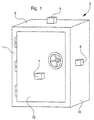
- Figure 1 shows an enclosure 1 of a safe 3 equipped with three detectors 5 to 7 connected to a alarm system (not shown). Detectors 5 and 6 are placed respectively on walls 9 and 10 of enclosure 1, and detector 7 is placed on a door access 12 to the safe 3. Such detectors are arranged to be able to measure a parameter related to the enclosure, for example a vibration or an elevation of temperature, and to be able to send a signal in response can trigger, via the alarm system, the supply an alarm signal, for example a telephone call.
- a parameter related to the enclosure for example a vibration or an elevation of temperature
- detectors 5 to 7 are arranged to detect a vibration propagating on one of the walls 9 or 10, and on the door 12. Let’s consider also the case where door 12 is the subject of a attempted break-in, and that this attempt causes propagation of a vibration on this door.
- the equipment described in connection with FIG. 1 then makes it possible to remotely report the existence of an abnormal situation in the environment of the enclosure.
- Document FR 2,694,650 describes a system comprising a sensor capable of detecting waves from air mass movements due to the opening of a door or a window in an enclosed space. This system can receive the signal from the sensor, compare this signal to memorized signals and, in the event of recognition of these signals, provide an alarm control signal corresponding to the opening of the door or window.
- Document DE-A-44 38 168 describes a lock of a access door, comprising: a mechanism capable of controlling locking and / or unlocking the door access; specific sensors or transducers to detect a hole through the lock, or an opening in the access door; and an alarm system comprising a unit which may, in response to detection of one sensors, activate an alarm siren.
- detectors work is independent of phenomena occurring in the environment of the enclosure, such as a rise in temperature linked to an expected seasonal climatic phenomenon.
- Another disadvantage of the detector in Figure 1 is that it should be placed on one of the walls of the enclosure, making the detector visible from outside, so that it can be subject to fraudulent manipulation.
- the second type of protective devices is commonly called "informer".
- FIG. 2A represents a rear front view of a access door 18 allowing access to a safe such than that shown in Figure 1, a panel of this door having been removed to allow the structure to be seen internal of such a door.
- the door 18 is conventionally fitted with locks 20, a linkage 22 and an informer 24, the operation will be explained below.
- the informer 24 includes a mechanism 26 capable of immobilizing the linkage 22, this mechanism being independent of the lock 20.
- the informer 24 further comprises a device of arming 28 suitable for maintaining this mechanism in a so-called retaining position.
- the mechanism 26 consists of two locks 29 which are arranged to be able to immobilize the linkage 22, so that when you want to train then the linkage 22 for unlocking the access door, this unlocking is no longer allowed, like a blockage caused by the bolt of the lock from this door.
- the arming device 28 can be consisting of a glass plate connected to latches and preloaded springs, these components being arranged so that the informer is kept in a pre-stressed position, or retaining position.
- the existing informers are essentially thermal informers capable of triggering following a anomalous evolution of the ambient temperature of the environment in which these informers are arranged. he there are also shock informers suitable for trigger following a shock applied to the protected wall by such a informer.
- Figure 2B illustrates the operation of the informer 24, in the event that door 18 is the subject of an attempt burglary.
- this attempt breaking has the effect of releasing the device armament 28 relative to its retaining position, and activate the informer 24.
- the various components, and including locks 29, which were originally prestressed are moved to a position where they immobilize the linkage 22. Consequently, the door 18 remains in the locked position, preventing any no one to open the safe. In other words, the attempted break-in is made unsuccessful.
- the document EP 0.686.744 describes a system of lock to prevent a door from opening enclosed space where the atmosphere can be harmful to humans.
- this system can detect the concentration of oxygen in the confined space, and provide a signal proportional to this concentration. If the latter is included in a predetermined range, the system can control the locking the access door.
- the third type of known protective device has intended to neutralize an aggressor, when he attempts a break-in on the enclosure.
- a device may release toxic gas, electric shock or jet of flames. In general, the installation of such devices is legally prohibited.
- the Applicant of the present invention has observed that many of the security enclosure protection only provide late reporting of a break-in including the enclosure is the object, that is to say after the break-in was successful, often after several hours of work on the enclosure.
- the break-in can be: an explosion of the enclosure continued to the massive injection of an explosive gas into the environment of the enclosure; or a tearing of the enclosure following a repetitive hammering.
- An object of the present invention is to provide a lock overcoming the aforementioned drawbacks and, more specifically, an enclosure access door lock security, this lock can manage the evolution of a parameter derived from a phenomenon occurring in the environment of the enclosure.
- Another object of the present invention is to provide a lock that can determine the nature of the phenomenon to the origin of an abnormal evolution of the detected parameter and, in response to this determination, order the locking or unlocking the access door.
- Another object of the present invention is to provide a lock that can adapt to changing parameters linked to the surrounding environment, so as to avoid locking or unlocking the access door, following an abnormal evolution of the parameter, caused by normal activity in the environment of the enclosure.
- Another object of the present invention is to provide a lock that meets the usual concerns of rationality and cost.
- the subject of the invention is an access door lock a security enclosure arranged in an environment.
- This lock includes a mechanism that can control, in response to a setpoint, locking and / or unlocking of said door, storage means may contain reference data relating to a parameter linked to this environment, in particular thresholds predetermined depending on said environment, and / or the material arrangement of said enclosure, and / or daily activity in said environment.
- This lock further includes a processing unit capable of receive measurement data of said parameter provided by a transducer, as well as said data of reference, determine if it is normal for the phenomenon to the origin of an anomalous evolution of said parameter had place and, depending on the result of this determination, providing said control instruction to said mechanism.
- the lock can provide the locking control on its own and / or unlocking, from the measured values of the parameter, which achieves centralized management of this control, and gives the lock management autonomy of the evolution of the parameter.
- the lock according to the present invention corresponds to a new type of protection device against attempts break-in on the enclosure, making it possible to detect a anomalous evolution of a parameter linked to the environment, to analyze this evolution, and to order in response the locking and / or unlocking the access door.
- the access door when locked by the lock does not requires no destructive intervention to be able to new access to the enclosure, unlike classical informers described above in relation to Figures 2A and 2B.
- the access door can be unlocked by a locker provided by a code specific, this instruction being provided from the exterior, for example through a connection to a portable processing unit.
- Another advantage of such an arrangement is that the lock may cause locking and / or unlocking the access door without using an additional connection to the linkage of this door.
- An advantage of being able to contain such data reference is to allow a programmer to adapt the lock to the environment of the enclosure, so as to avoid unnecessary unlocking or locking of the access door, following an anomalous evolution of the parameter measured, caused by normal activity in the environment of the enclosure or by a phenomenon local climate change.
- Such lock can advantageously provide an order as preventive, from the detection of the first steps of a anomalous evolution of the parameter.
- the unity of treatment of the lock according to the present invention is arranged to produce, among a plurality of signatures, an identification of the signature which corresponds to data relating to the measurement of the parameter, which advantage of determining the nature of a phenomenon to the origin of an anomalous evolution of the parameter, before decide whether the access door should be locked or unlocked. This allows in particular to avoid a door lock accidentally released of access, for example under the influence of a harmless shock, without that no attempted break-in has actually taken place location.
- the means of memorizing the lock according to the present invention may receive and contain data relating to the measurement of the parameter, so as to update a log events retracing the history of the lock, which has the advantage of providing monitoring of the measured values of the parameter, i.e. to allow a posteriori a analysis of events in the history of the lock, especially those relating to possible break-ins.
- Another advantage linked to the arrangement of such means of memorization is to guarantee the survival of the data contained in the event log, since this the latter is contained in the lock itself.
- the lock according to the present invention incorporates the transducer, which has for the advantage of strengthening the autonomy of the lock.
- the latter thus includes a restricted number components which, arranged in a monolithic manner, perform the locking and locking functions unlocking of the access door, as well as that of management of the evolution of the parameter, which responds to usual concerns of rationality and cost.
- Another advantage linked to the incorporation of transducer in the lock is to guarantee discretion and the camouflage of the protection device produced by the lock, especially the fact that the transducer is not more visible outside the enclosure.
- the lock according to the present invention may include an interface for communication linked to the processing unit, which has the advantage of allowing an outside user to the enclosure to remotely monitor this enclosure, without that it is necessary to place a video camera proximity to the enclosure, this camera being difficult to install and expensive.
- the user can have remote knowledge of an anomalous evolution of the parameter measured and, thus, predict the future evolution of this parameter, in order to determine if this evolution derives an involuntary phenomenon (for example a seasonal temperature increase) or voluntary (e.g. attempted break-in brought on the enclosure).
- the lock according to the present invention can provide signaling to the user at the start of an attempt break-in on the enclosure, which also allows avoid inadvertent locking or unlocking from the access door.
- Another advantage linked to the arrangement of such communication interface is to remotely get a followed by the measured values of the parameter, these values can be recorded in an event log which is offset from the enclosure.
- This newspaper can thus constitute a memory of the lock, which can be analyzed a posteriori to identify the author (s) of an attempted break-in.
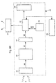
- FIG. 3A represents a diagram in the form of blocks of a first embodiment of a lock according to the present invention, designated by the reference 31.
- the lock 31 is intended to equip an access door a safety enclosure (not shown in FIG. 3A) arranged in an environment.
- This lock includes a mechanism 33 which can control, in response to a setpoint control, locking and / or unlocking said access door.
- a mechanism 33 which can control, in response to a setpoint control, locking and / or unlocking said access door.
- the command setpoint can thus order the locking or release of the linkage from the access door.
- the lock 31 further comprises a unit of processing 37 connected to mechanism 33 and capable of managing a change of state of lock 31 (i.e. a locking or unlocking the access door), and guarantee the current state.
- a processing unit 37 the component sold under the name "H83834" by the company "Hitachi", this component being arranged and programmed as described in more detail below.
- the processing unit 37 is connected to a transducer 35 arranged to provide measurement values X0 of a parameter X linked to the environment of the enclosure, this parameter being able to evolve following a phenomenon producing in the enclosure environment.
- the parameter X in the current case of an enclosure provided with metal walls, the parameter X can be the ambient temperature outside or at inside the enclosure, this temperature can be thermally conducted by these walls.
- the transducer 35 used in lock 31 includes a ohmic resistance varying according to the temperature, such resistance being known to those skilled in the art. In the preferred case where the access door is equipped with a electronic lock, said resistance is arranged on the electronic circuit which supports this lock.
- the parameter X can be a vibration likely to propagate on a wall of the enclosure.
- the transducer 35 comprises a accelerometer such as that marketed under the reference “ADXLOS" by the company “Analog Device”.
- ADXLOS the reference
- said accelerometer is fitted on the electronic circuit which supports this lock.
- the parameter X can be the presence of a foreign body enjoying a physiological activity emitting signals having a wavelength belonging to the infrared domain.
- the transducer 35 comprises a detector of presence known per se, arranged so as to be able detect, for example, the presence of a locked up person in the enclosure, and provide in response a logic signal to the processing unit 37, the latter being able to warn of such presence a user outside of the enclosure.
- the unit of processing 37 is arranged to receive data relating to the measurement of parameter X, in particular the measured values X0 supplied by the transducer 35.
- the lock 31 further comprises means for shaping 39 connected to the transducer 35, and a analog-digital converter 41 connected to the means 39 and the processing unit 37.
- the shaping means 39 are arranged in such a way so that they can receive from transducer 35 them measured values X0, and provide first data designated X1 from the measurement of parameter X, as this is described below.
- the means of placing shaped 39 include bandpass filters programmable known per se.
- the analog-digital converter 41 is arranged so that it can receive in analog form X1 data, convert that data to digital form in second data designated X2, and provide to the processing unit 37 the data X2.
- analog-to-digital converter 41 we used as analog-to-digital converter 41 the analog-to-digital converter integrated in the component "H83834" already described above.
- measured values X0 can be processed by the processing unit 37.
- the lock 31 includes storage means 43 which can contain third data or relative reference data at parameter X, this data being preprogrammed during installation of the speaker in an environment specific.
- the reference X3 will designate this reference data.
- these data constitute thresholds predetermined depending on the environment and / or the physical arrangement of the enclosure, and / or activity daily in the environment.
- the predetermined thresholds may include minimum and / or maximum values of parameter X, and / or minimum and / or maximum values of its variation over a predetermined period.
- ily activity corresponds to a succession of first time slots during which the access door can be unlocked or locked, by providing the lock 31 with access codes, and second schedules during which the door access cannot be unlocked.
- the storage means 43 are connected to the processing unit 37, so that this unit can access X3 data.
- storage means 43 the EEPROM memory marketed under the name "X24325S” by the company "XICOR".
- the processing unit 37 can be arranged to compare the predetermined thresholds with the X2 data, way to determine if an abnormal evolution of the parameter X is within the range delimited by said value minimum and / or said maximum value. According to the result of this comparison, the processing unit 37 can provide mechanism 33 with the locking instruction or unlocking. In other words, the processing unit 37 checks whether the measured values X0, after setting form and conversion, are within a range in which the values of parameter X, or those of its variations, are considered normal, i.e. occurring during normal activity in the environment of the enclosure.
- Lock 31 is particularly suitable for management of the air temperature present in the environment of the enclosure, as illustrated by in more detail below.
- the lock 31 incorporates, preferably all the components connected to the treatment 37. This incorporation is illustrated in figure 3A and following, by a line shown in dotted lines. However, as an alternative embodiment, it goes from so that the transducer 35 can be arranged close to the lock according to the present invention, without being there incorporated.
- FIG. 3B represents a diagram in the form of blocks of a second embodiment of a lock according to the present invention, designated by the reference 44. It will be noted that objects represented in FIG. 3B and designated by the same references as objects represented in FIG. 3A are substantially identical to those described in relation to FIG. 3A.
- the storage means 43 of the lock 44 contain fourth data designated X4 comprising a plurality of predetermined data or signatures, each signature corresponding to data representing the effect on the parameter X of a phenomenon known.
- this condition may be voluntary in nature (e.g. piercing of the access door, or a change in the bolt position lock following picking of this lock) or involuntary (for example an industrial activity producing near the enclosure, or activity atmospheric temperature change).
- Signatures can be stored for this purpose during the installation of lock 44, like the data X3.
- these signatures can understand the vibrations specific to the operation of a air conditioning, or the use of a jackhammer near the enclosure.
- the storage means 43 may contain as signatures the X2 data from the measurement of parameter X.
- the processing unit 37 of the lock 44 is also arranged so that it can achieve, among the signatures contained in the means of memorization 43, an identification of the signature which is substantially equal to the X2 data from the transducer 35.
- the processing unit 37 checks whether the variation over a predetermined period of time measured parameter X, after formatting and conversion, is substantially equal to one of the signatures known by the lock 44.
- the processing unit 37 supplies the mechanism 33 an instruction likely to command a locking and / or unlocking the access door. In other words, the processing unit 37 can thus determine if an abnormal evolution of the measured parameter X is related to a known phenomenon, i.e. if it is normal that this phenomenon took place.
- Lock 44 is particularly suitable for management of the vibration likely to spread on the enclosure walls, as shown so more detailed below.
- the lock 31, as well as the lock 44 may include a communication interface 45 connected to the processing unit 37, this interface comprising data display means allowing, where appropriate, display of the lockout setpoint or release provided to mechanism 33, and / or display X0 measurement data.
- Communication interface 45 may also include means for introducing data, so the processing unit 37 can establish one-way communication or bidirectional with a user outside the environment of the enclosure. So the unity of processing 37 can transfer to this user the measured values of parameter X and, where applicable, the locking and / or locking instruction supplied to mechanism 33.
- the external user can remotely interrogate the processing unit 37 to provide a new lockout or unlocking to validate or invalidate the one provided in response to measured values X0. He can also modify the X3 data contained in the means of memorization 43.
- This improved embodiment of the lock 31, as well as lock 44, is particularly suitable for managing the presence of a person in the enclosure. Indeed, consider the case where the enclosure is provided a conventional presence detector. Suppose then, after locking the access door, a person is locked in the enclosure. The arrangement described above allows in this case to detect the presence of this person, and allows to provide in response the display of a message to the external user, via the interface communication 45. In this case, this user can remotely decide to unlock (or lock) the access door, to allow (or not allow) the release of the person locked in the enclosure.
- the lock 31, as well as the lock 44 may further comprise means 47 for provide alarm signals.
- these means are arranged so that they provide alarm signals, when they receive alarm control signals.
- these means consist of at least one bistable relay known per se, to which is connected, by example, a telephone transmitter or a transmitter sound.
- the supply means 47 are connected to the processing unit 37, so that this unit can provide alarm control signals, depending results from said comparison and / or said identification of the data coming from the transducer 35, this comparison and this identification being carried out by the processing unit 37.
- a programmer can enter a range of temperature or a range of temperature gradient, in the storage means 43, via the interface of communication 45 and the processing unit 37.
- a range is defined by said minimum value and / or said maximum value so that when an evolution of the ambient temperature corresponds to values included in this range, this evolution is considered to be normal.
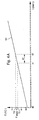
- FIG. 4A represents a curve Experimental 51 illustrating the evolution of temperature T during the designated time t, the temperature T being the ambient temperature linked to the environment of the enclosure.
- the transducer 35 continuously supplies a value of the temperature T at processing unit 37 which analyzes periodically the values supplied by the transducer 35.
- the temperature T thus measured is worth T1 then, at an instant t2, it is worth T2, the interval of time between instants t1 and t2 corresponding to a predetermined measurement period ⁇ t.
- the reference Tmax designates the maximum temperature value T, above which it is considered to reflect an abnormal situation.
- the temperature T measured at time t1 is less than the value Tmax, while the temperature T measured at time t2 is greater than this value. Consequently, the processing unit 37 can order the alarm means 47 to supply alarm signals, to signal to a data subject the existence of an abnormal situation in the environment of the enclosure, linked to an abnormal rise in its temperature room.
- FIG. 4B represents an experimental curve 55 illustrating the evolution of the temperature T during the designated time t. So in this example, at an instant t3, the temperature T thus measured is worth T3 then, at an instant t4, it is worth T4, the interval of time between instants t3 and t4 corresponding to a predetermined measurement period ⁇ t.
- the reference ⁇ T designates the temperature difference between two measurements consecutive.
- the processing unit 37 determines the temperature gradient between times t3 and t4, that is to say the ratio ⁇ T / ⁇ t.
- Figure 4B illustrates the case where the temperature gradient is included in said beach, this situation being represented during the period delimited by the initial instant- t0 and an instant t5 (see arrow A). Now suppose that said gradient is located outside of said range. This situation is illustrated in FIG. 4B and, more particularly, in the period starting at time t5 (see arrow B). In Consequently, the processing unit 37 controls the means alarm 47 the supply of alarm signals, for report to a data subject the existence of a abnormal situation in the environment of the enclosure, linked to an abnormal rise in the temperature gradient ambient T.
- a programmer can introduce signatures in the storage means 43, via the communication interface 45 and the processing unit 37.
- Figure 5A represents a curve 61 illustrating the evolution of the first vibration X0 measured over time t.
- the transducer 35 provides a sample of the time course of the first vibration X0.
- the sample in FIG. 5A corresponds to a time window of 100 ms.
- the processing unit 37 determines the spectral image of this sample.
- FIG. 5B represents a curve 63 illustrating a spectral image of the sample represented in FIG. 5A. Then the processing unit 37 analyzes this image to extract three main frequencies corresponding to the three maximum amplitudes of said spectral image.
- the references A1 to A3 denote the three main amplitudes, and the references F1 to F3 denote the three corresponding frequencies.
- Table 1 represents the three main amplitudes Ai and the associated frequencies Fi, resulting from experimental results carried out by the Applicant of the present invention, in relation to FIGS. 5A and 5B.
- i 1 2 3 Have 1.00 0.68 0.38 Fi (Hz) 51 680 650
- the processing unit 37 checks whether the three couples (Fi, Ai) do not correspond to one known signature (i.e. to couples previously introduced by the programmer, during the installation of the system, or in past experiences).
- the unit of processing 37 does not control the supply of signals alarm.
- the unit of processing 37 orders in response the supply of alarm signals, via the supply means 47.
- the programmer or a authorized user must provide a response in response at lock 44.
- This instruction validates if the processing unit 37 must consider said evolution as the effect of a normal or abnormal situation, in introducing as a signature in the means of memorization 43 the three couples (Fi, Ai).
- lock 44 is thus provided with a memory or learning function allowing to acquire data coming under its experience, within a specific environment in which this lock is arranged. This gives it advantageously the faculty of an interpretation "intelligent" events that disturb it in the part of his daily exercise.
- the Applicant of the present invention experimentally produced a second vibration X0 using the same vibrating drill as that used in connection with FIGS. 5A and SE, but applied to a different location.
- the references used to describe the first vibration X0 will also be used for describe the second vibration X0.
- FIGS. 5C and 5D represent the experimental results linked to the second vibration X0, and table 2 represents the three main amplitudes Ai and the associated frequencies Fi, linked to the second vibration X0.
- i 1 2 3 Have 1.00 0.67 0.35 Fi (Hz) 52 680 650
- the time sample of the second vibration X0 has a waveform 65 different from that of the sample represented in FIG. 5A (i.e. the curve 61).
- the spectral image of the second vibration X0 has a form wave 66 identical to that shown in Figure 5B.
- the first and second vibrations X0 made by the Applicant of the present invention provide two different time samples (shown in Figures 5A and 5C, respectively) which have two identical spectral images (shown in figures 5B and 5D, respectively).
- the first and second vibration X0 come from the same phenomenon (the application of an electric drill on a wall of the enclosure), this phenomenon being associated with a signature specific corresponding to the spectral images of the figures 5B and 5D.
- the Applicant of the present invention has experimentally performed a third vibration X0 at using a grinder applied to said wall.
- a grinder applied to said wall Through for the sake of simplicity, the references used to describe the first and second vibrations X0 will be used also to describe the third vibration X0.
- Figures 5E and 5F show the results experimental linked to the third vibration X0.
- the time sample of the third vibration X0 has a waveform 69 which is significantly different from that of the samples shown in Figures 5A and 5C (i.e. curves 61 and 65 respectively).
- the third vibration X0 has a spectral image which has a substantially 70 waveform different from that shown in Figure 5B (i.e. curve 63).
- the third vibration X0 is associated with a signature different from that associated at the first and second vibrations X0, which confirms the existence of a signature specific to the grinder, and a signature specific to the electric drill. Therefore, the processing unit 37 orders in response the supply alarm signals, via the supply means 47.
- a lock can be provided according to the present invention capable of managing the evolution of a sound signal neighboring the enclosure, or that of the fraction molar of a gas present in the environment of this pregnant.
- a lock can be provided according to the present invention capable of managing changes in several parameters related to the environment of the enclosure equipped with a lock according to the present invention, by connecting to said unit of processing this lock of the appropriate transducers in parallel.
Landscapes
- Physics & Mathematics (AREA)
- General Physics & Mathematics (AREA)
- Engineering & Computer Science (AREA)
- Computer Security & Cryptography (AREA)
- Lock And Its Accessories (AREA)
Abstract
Description
La présente invention _concerne le domaine des serrures de porte d'accès destinées à équiper des enceintes de sécurité telles que des coffres-forts et des chambres fortes. L'invention concerne plus particulièrement une serrure de porte d'accès équipant une enceinte de sécurité, cette serrure pouvant gérer l'évolution d'un paramètre lié à l'environnement de ladite enceinte.The present invention relates to the field of access door locks intended to equip security enclosures such as safes and strong rooms. The invention relates more particularly an access door lock fitted to a security enclosure, this lock can manage the evolution of a parameter linked to the environment of said pregnant.
Face à la sophistication croissante des agressions commises sur des enceintes de sécurité, on cherche pour protéger de telles enceintes à pouvoir détecter des situations anomales induites par des perturbations de natures de plus en plus diversifiées.Faced with the growing sophistication of attacks committed on security enclosures, we are looking for protect such enclosures to be able to detect anomalous situations induced by disturbances of increasingly diverse natures.
Une porte d'accès d'une enceinte de coffre-fort ou de chambre forte comprend classiquement une "tringlerie", c'est-à-dire un ensemble constitué de tringles et de barres formant un système de commande susceptible de verrouiller ou de déverrouiller la porte d'accès. En général, cette porte comprend en outre une serrure munie d'un pêne, ce pêne pouvant, sur commande libérer ou bloquer la tringlerie, de telle sorte que, lorsqu'on commande l'entraínement de la tringlerie pour réaliser un verrouillage ou un déverrouillage de la porte d'accès, ce verrouillage ou ce déverrouillage est ou n'est pas permis.An access door to a safe enclosure or vault conventionally includes a "linkage", that is to say a set consisting of rods and bars forming a control system capable of lock or unlock the access door. In general, this door further comprises a lock provided a bolt, this bolt being able, on command, to release or lock the linkage so that when controls the linkage drive to achieve a locking or unlocking the access door, this locking or unlocking is or is not allowed.
De façon générale, il existe trois types de dispositifs de protection adaptés pour protéger des enceintes contre des tentatives d'effraction.Generally speaking, there are three types of protective devices suitable for protecting pregnant against attempted break-ins.
Le premier type de dispositif de protection qui est communément utilisé dans le domaine des coffres-forts et des chambres fortes, est usuellement appelé "détecteur".The first type of protective device which is commonly used in the field of safes and vaults, is usually called "detector".
La figure 1 représente une enceinte 1 d'un coffre-fort
3 équipé de trois détecteurs 5 à 7 reliés à un
système d'alarme (non représenté). Les détecteurs 5 et 6
sont placés respectivement sur des parois 9 et 10 de
l'enceinte 1, et le détecteur 7 est placé sur une porte
d'accès 12 du coffre-fort 3. De tels détecteurs sont
agencés pour pouvoir mesurer un paramètre lié à
l'enceinte, par exemple une vibration ou une élévation de
température, et pour pouvoir émettre en réponse un signal
pouvant déclencher, via le système d'alarme, la fourniture
d'un signal d'alarme, par exemple un appel téléphonique.Figure 1 shows an
Considérons le cas où les détecteurs 5 à 7 sont
agencés pour détecter une vibration se propageant sur
l'une des parois 9 ou 10, et sur la porte 12. Considérons
également le cas où la porte 12 est l'objet d'une
tentative d'effraction, et que cette tentative provoque la
propagation d'une vibration sur cette porte. L'équipement
décrit en relation avec la figure 1 permet alors de
signaler à distance l'existence d'une situation anormale
dans l'environnement de l'enceinte.Consider the case where
Dans le domaine des systèmes d'alarme, il existe bon nombre de détecteurs dont le fonctionnement est proche de celui décrit en relation avec la figure 1.In the area of alarm systems, there are good number of detectors operating close to that described in relation to FIG. 1.
Le document FR 2.694.650 décrit un système comprenant un capteur pouvant détecter les ondes issues des mouvements de masse d'air dus à l'ouverture d'une porte ou d'une fenêtre dans un espace clos. Ce système peut recevoir le signal du capteur, comparer ce signal à des signaux mémorisés et, dans le cas où il y a reconnaissance de ces signaux, fournir un signal de commande d'une alarme correspondant à l'ouverture de la porte ou de la fenêtre.Document FR 2,694,650 describes a system comprising a sensor capable of detecting waves from air mass movements due to the opening of a door or a window in an enclosed space. This system can receive the signal from the sensor, compare this signal to memorized signals and, in the event of recognition of these signals, provide an alarm control signal corresponding to the opening of the door or window.
Le document DE-A-44 38 168 décrit une serrure d'une porte d'accès, comprenant : un mécanisme pouvant commander le verrouillage et/ou le déverrouillage de la porte d'accès; des capteurs ou transducteurs propres à détecter un perçage à travers la serrure, ou une ouverture de la porte d'accès; et un système d'alarme comprenant une unité de traitement pouvant, en réponse à une détection de l'un des capteurs, activer une sirène d'alarme.Document DE-A-44 38 168 describes a lock of a access door, comprising: a mechanism capable of controlling locking and / or unlocking the door access; specific sensors or transducers to detect a hole through the lock, or an opening in the access door; and an alarm system comprising a unit which may, in response to detection of one sensors, activate an alarm siren.
Un inconvénient de tels détecteurs réside dans le fait que, en cas de tentative d'effraction, le détecteur n'est pas en mesure de provoquer le verrouillage de la porte.One drawback of such detectors lies in the causes the detector to attempt to break in is unable to lock the door.
Un autre inconvénient de tels détecteurs réside dans le fait que leur fonctionnent est indépendant des phénomènes se produisant dans l'environnement de l'enceinte, telle qu'une élévation de la température liée à un phénomène climatique saisonnier attendu. Another disadvantage of such detectors lies in the fact that they work is independent of phenomena occurring in the environment of the enclosure, such as a rise in temperature linked to an expected seasonal climatic phenomenon.
Un autre inconvénient du détecteur de la figure 1 réside dans le fait qu'il doit être placé sur l'une des parois de l'enceinte, ce qui rend le détecteur visible de l'extérieur, de telle sorte qu'il peut faire l'objet de manipulations frauduleuses.Another disadvantage of the detector in Figure 1 is that it should be placed on one of the walls of the enclosure, making the detector visible from outside, so that it can be subject to fraudulent manipulation.
Le deuxième type de dispositifs de protection est communément appelé "délateur".The second type of protective devices is commonly called "informer".
La figure 2A représente une vue de face arrière d'une
porte d'accès 18 permettant l'accès à un coffre-fort tel
que celui représenté en figure 1, un panneau de cette
porte ayant été enlevé pour permettre de voir la structure
interne d'une telle porte.FIG. 2A represents a rear front view of a
La porte 18 est équipée classiquement de serrures 20,
d'une tringlerie 22 et d'un délateur 24 dont le
fonctionnement sera expliqué ci-après. Le délateur 24
comprend un mécanisme 26 susceptible d'immobiliser la
tringlerie 22, ce mécanisme étant indépendant de la
serrure 20. Le délateur 24 comprend en outre un dispositif
d'armage 28 propre à maintenir ce mécanisme dans une
position dite de retenue. Dans l'exemple représenté en
figure 2A, le mécanisme 26 est constitué de deux verrous
29 qui sont agencés pour pouvoir immobiliser la tringlerie
22, de telle sorte que, lorsqu'on désire ensuite entraíner
la tringlerie 22 pour réaliser un déverrouillage de la
porte d'accès, ce déverrouillage n'est plus permis, à
l'instar d'un blocage provoqué par le pêne de la serrure
de cette porte. Le dispositif d'armage 28 peut être
constitué d'une plaque de verre reliée à des verrous et à
des ressorts précontraints, ces composants étant agencés
de telle sorte que le délateur est maintenu dans une
position précontrainte, ou position de retenue.The
Les délateurs existant sont essentiellement des délateurs thermiques propres à se déclencher suite à une évolution anomale de la température ambiante de l'environnement dans lequel sont agencés ces délateurs. Il existe également des délateurs à choc propres à se déclencher suite à un choc appliqué sur la paroi protégée par un tel délateur. The existing informers are essentially thermal informers capable of triggering following a anomalous evolution of the ambient temperature of the environment in which these informers are arranged. he there are also shock informers suitable for trigger following a shock applied to the protected wall by such a informer.
La figure 2B illustre le fonctionnement du délateur
24, dans le cas où la porte 18 est l'objet d'une tentative
d'effraction.Figure 2B illustrates the operation of the
Comme le représente la figure 2B, cette tentative
d'effraction a pour effet de libérer le dispositif
d'armage 28 par rapport à sa position de retenue, et de
rendre actif le délateur 24. Les différents composants, et
notamment les verrous 29, qui étaient initialement
précontraints sont déplacés dans une position où ils
immobilisent la tringlerie 22. En conséquence, la porte 18
demeure en position de verrouillage, ce qui empêche toute
personne d'ouvrir le coffre-fort. Autrement dit, la
tentative d'effraction est rendue infructueuse.As shown in Figure 2B, this attempt
breaking has the effect of releasing the
Dans le domaine général de la serrurerie, il existe également des délateurs dont le fonctionnement est proche de celui décrit en relation avec les figures 2A et 2B.In the general field of locksmithing, there are also informers whose functioning is close of that described in relation to FIGS. 2A and 2B.
Le document EP 0.686.744 décrit un système de verrouillage pour empêcher l'ouverture d'une porte d'un espace clos où l'atmosphère peut être nocive pour l'homme. ce système peut détecter la concentration de l'oxygène dans l'espace clos, et fournir un signal proportionnel à cette concentration. Si cette dernière est comprise dans une plage prédéterminée, le système peut commander le verrouillage de la porte d'accès.The document EP 0.686.744 describes a system of lock to prevent a door from opening enclosed space where the atmosphere can be harmful to humans. this system can detect the concentration of oxygen in the confined space, and provide a signal proportional to this concentration. If the latter is included in a predetermined range, the system can control the locking the access door.
Un inconvénient de tels délateurs réside dans le fait qu'ils ne réalisent pas une analyse de la nature du phénomène à l'origine de la variation anomale détectée, et qu'ils commandent le verrouillage ou le déverrouillage de la porte, suite à une détection des effets du phénomène, et non des causes qui ont pu induire ce phénomène. Typiquement, leur fonctionnent est indépendant des phénomènes se produisant dans l'environnement de l'enceinte, par exemple une élévation de la température liée à un phénomène climatique saisonnier se produisant naturellement dans cet environnement. Ainsi, suite à une telle élévation de la température, lesdits délateurs réalisent inutilement un verrouillage ou un déverrouillage de la porte, étant donné que le phénomène détecté est issu des forces de la nature.One drawback of such informers is that that they don't do an analysis of the nature of the phenomenon at the origin of the anomalous variation detected, and that they control the locking or unlocking of the door, following a detection of the effects of the phenomenon, and not of the causes which could have induced this phenomenon. Typically, their function is independent of phenomena occurring in the environment of the enclosure, for example a rise in temperature linked to a seasonal climatic phenomenon occurring naturally in this environment. So, following a such temperature rise, said informers unnecessarily lock or unlock of the door, since the detected phenomenon originated forces of nature.
En outre, dans le domaine particulier des coffres-forts et des chambres fortes, un inconvénient majeur du délateur du type de ceux des figures 2A et 2B réside dans le fait que la porte d'accès lorsqu'elle est verrouillée, nécessite une intervention destructrice pour pouvoir à nouveau accéder dans l'enceinte, et pour ramener les différents composants de ce délateur dans leur position initiale de retenue. Cette intervention occasionne des coûts de réparation élevés.In addition, in the particular field of safes and vaults, a major drawback of the type of those of FIGS. 2A and 2B resides in the fact that the access door when it is locked, requires destructive intervention to be able to again enter the enclosure, and to bring the different components of this informer in their position initial retainer. This intervention causes high repair costs.
Un autre inconvénient de ces délateurs réside dans le fait qu'ils peuvent se déclencher accidentellement, par exemple sous l'effet d'un choc anodin sur la porte d'accès, sans qu'aucune tentative d'effraction n'ait effectivement eu lieu. Ce type de déclenchement intempestif occasionne néanmoins une intervention destructrice sur cette porte et, par conséquent, des coûts de réparation élevés. Ceci est d'autant plus préjudiciable que les délateurs de certaines enceintes de coffres-forts de banques sont agencés pour commander, en cas d'effraction détectée, un système qui macule les billets de banque contenus dans l'enceinte.Another disadvantage of these informers is the fact that they can fire accidentally, by example under the effect of a harmless shock on the door access, without any attempted break-in having actually occurred. This type of trigger untimely nevertheless causes an intervention destructive on this door and therefore costs high repair costs. This is all the more harmful that the informers of certain safe enclosures banks are arranged to order, in case of burglary detected, a system which stains the banknotes bank contained in the enclosure.
Le troisième type de dispositif de protection connu a pour but de neutraliser un agresseur, lorsqu'il tente une effraction sur l'enceinte. Typiquement, un tel dispositif peut libérer un gaz toxique, une décharge électrique ou un jet de flammes. En général, l'installation de tels dispositifs est légalement interdite.The third type of known protective device has intended to neutralize an aggressor, when he attempts a break-in on the enclosure. Typically, such a device may release toxic gas, electric shock or jet of flames. In general, the installation of such devices is legally prohibited.
Par ailleurs, la Demanderesse de la présente invention a observé que bon nombre des dispositifs de protection d'enceinte de sécurité ne fournissent que tardivement la signalisation d'une effraction dont l'enceinte fait l'objet, c'est-à-dire après que l'effraction ait réussie, souvent à l'issue de plusieurs heures de travail sur l'enceinte. Par exemple, l'effraction peut être : une explosion de l'enceinte suite à l'injection massive d'un gaz explosif dans l'environnement de l'enceinte ; ou un arrachement de l'enceinte suite à un martèlement répétitif.Furthermore, the Applicant of the present invention has observed that many of the security enclosure protection only provide late reporting of a break-in including the enclosure is the object, that is to say after the break-in was successful, often after several hours of work on the enclosure. For example, the break-in can be: an explosion of the enclosure continued to the massive injection of an explosive gas into the environment of the enclosure; or a tearing of the enclosure following a repetitive hammering.
Un but de la présente invention est de prévoir une serrure palliant les inconvénients susmentionnés et, plus précisément, une serrure de porte d'accès d'une enceinte de sécurité, cette serrure pouvant gérer l'évolution d'un paramètre dérivée d'un phénomène se produisant dans l'environnement de l'enceinte.An object of the present invention is to provide a lock overcoming the aforementioned drawbacks and, more specifically, an enclosure access door lock security, this lock can manage the evolution of a parameter derived from a phenomenon occurring in the environment of the enclosure.
Un autre but de la présente invention est de prévoir une serrure pouvant déterminer la nature du phénomène à l'origine d'une évolution anomale du paramètre détecté et, en réponse à cette détermination, commander le verrouillage ou le déverrouillage de la porte d'accès.Another object of the present invention is to provide a lock that can determine the nature of the phenomenon to the origin of an abnormal evolution of the detected parameter and, in response to this determination, order the locking or unlocking the access door.
Un autre but de la présente invention est de prévoir une serrure pouvant s'adapter aux évolutions de paramètre liées à l'environnement de l'enceinte, de manière à éviter un verrouillage ou un déverrouillage de la porte d'accès, suite à une évolution anomale du paramètre, provoquée par une activité normale dans l'environnement de l'enceinte.Another object of the present invention is to provide a lock that can adapt to changing parameters linked to the surrounding environment, so as to avoid locking or unlocking the access door, following an abnormal evolution of the parameter, caused by normal activity in the environment of the enclosure.
Un autre but de la présente invention est de prévoir une serrure répondant aux préoccupations habituelles de rationalité et de coût.Another object of the present invention is to provide a lock that meets the usual concerns of rationality and cost.
Ces buts, ainsi que d'autres, sont atteints par la
serrure selon la revendication 1.These and other goals are achieved by
lock according to
L'invention a pour objet une serrure de porte d'accès d'une enceinte de sécurité disposée dans un environnement. Cette serrure comprend un mécanisme pouvant commander, en réponse à une consigne, le verrouillage et/ou le déverrouillage de ladite porte, des moyens de mémorisation pouvant contenir des données de référence relatives à un paramètre lié audit environnement, notamment des seuils prédéterminés dépendant dudit environnement, et/ou de l'arrangement matériel de ladite enceinte, et/ou de l'activité journalière dans ledit environnement. Cette serrure comprend en outre une unité de traitement pouvant recevoir des données de mesure dudit paramètre fournies par un transducteur, ainsi que lesdites données de référence, déterminer s'il est normal que le phénomène à l'origine d'une évolution anomale dudit paramètre ait eu lieu et, en fonction du résultat de cette détermination, fournir ladite consigne de commande audit mécanisme.The subject of the invention is an access door lock a security enclosure arranged in an environment. This lock includes a mechanism that can control, in response to a setpoint, locking and / or unlocking of said door, storage means may contain reference data relating to a parameter linked to this environment, in particular thresholds predetermined depending on said environment, and / or the material arrangement of said enclosure, and / or daily activity in said environment. This lock further includes a processing unit capable of receive measurement data of said parameter provided by a transducer, as well as said data of reference, determine if it is normal for the phenomenon to the origin of an anomalous evolution of said parameter had place and, depending on the result of this determination, providing said control instruction to said mechanism.
Un avantage d'un tel agencement est que la serrure peut assurer à elle-seule la commande de verrouillage et/ou de déverrouillage, à partir des valeurs de mesure du paramètre, ce qui réalise une gestion centralisée de cette commande, et confère à la serrure une autonomie de gestion de l'évolution du paramètre. Autrement dit, la serrure selon la présente invention correspond à un type nouveau de dispositif de protection contre des tentatives d'effraction sur l'enceinte, permettant de détecter une évolution anomale d'un paramètre lié à l'environnement, d'analyser cette évolution, et de commander en réponse le verrouillage et/ou le déverrouillage de la porte d'accès.An advantage of such an arrangement is that the lock can provide the locking control on its own and / or unlocking, from the measured values of the parameter, which achieves centralized management of this control, and gives the lock management autonomy of the evolution of the parameter. In other words, the lock according to the present invention corresponds to a new type of protection device against attempts break-in on the enclosure, making it possible to detect a anomalous evolution of a parameter linked to the environment, to analyze this evolution, and to order in response the locking and / or unlocking the access door.
Un autre avantage d'un tel agencement est que la porte d'accès une fois verrouillée par la serrure ne nécessite pas d'intervention destructrice pour pouvoir à nouveau accéder dans l'enceinte, contrairement aux délateurs classiques décrits ci-dessus en relations avec les figures 2A et 2B. En effet, la porte d'accès peut être déverrouillée par une consigne fournie par un code spécifique, cette consigne étant fournie depuis l'extérieur, par exemple par l'intermédiaire d'une connexion à une unité de traitement portable.Another advantage of such an arrangement is that the access door when locked by the lock does not requires no destructive intervention to be able to new access to the enclosure, unlike classical informers described above in relation to Figures 2A and 2B. Indeed, the access door can be unlocked by a locker provided by a code specific, this instruction being provided from the exterior, for example through a connection to a portable processing unit.
Un autre avantage d'un tel agencement est que la serrure peut provoquer un verrouillage et/ou un déverrouillage de la porte d'accès, sans avoir recours à un raccordement supplémentaire à la tringlerie de cette porte.Another advantage of such an arrangement is that the lock may cause locking and / or unlocking the access door without using an additional connection to the linkage of this door.
Un avantage de pouvoir contenir de telles données de référence est de permettre à un programmateur d'adapter la serrure à l'environnement de l'enceinte, de manière à éviter un déverrouillage ou un verrouillage inutile de la porte d'accès, suite à une évolution anomale du paramètre mesuré, provoquée par une activité normale dans l'environnement de l'enceinte ou par un phénomène climatique local. An advantage of being able to contain such data reference is to allow a programmer to adapt the lock to the environment of the enclosure, so as to avoid unnecessary unlocking or locking of the access door, following an anomalous evolution of the parameter measured, caused by normal activity in the environment of the enclosure or by a phenomenon local climate change.
Un autre avantage lié à de telles données de référence est de pouvoir commander le verrouillage et/ou le déverrouillage de la porte, en fonction du seuil prédéterminé, de sorte que cette commande peut avoir lieu dès les prémices de l'effraction. Autrement dit, une telle serrure peut avantageusement fournir une commande à titre préventif, dès la détection des premiers pas d'une évolution anomale du paramètre.Another benefit of such data reference is to be able to control the locking and / or unlocking the door, depending on the threshold predetermined, so this command can take place from the beginning of the break-in. In other words, such lock can advantageously provide an order as preventive, from the detection of the first steps of a anomalous evolution of the parameter.
Selon une autre caractéristique, l'unité de traitement de la serrure selon la présente invention est agencée pour réaliser, parmi une pluralité de signatures, une identification de la signature qui correspond aux données relatives à la mesure du paramètre, ce qui a pour avantage de déterminer la nature d'un phénomène à l'origine d'une évolution anomale du paramètre, avant de décider si la porte d'accès doit être verrouillée ou déverrouillée. Ceci permet notamment d'éviter un déclenchement accidentel du verrouillage de la porte d'accès, par exemple sous l'effet d'un choc anodin, sans qu'aucune tentative d'effraction n'ait effectivement eu lieu.According to another characteristic, the unity of treatment of the lock according to the present invention is arranged to produce, among a plurality of signatures, an identification of the signature which corresponds to data relating to the measurement of the parameter, which advantage of determining the nature of a phenomenon to the origin of an anomalous evolution of the parameter, before decide whether the access door should be locked or unlocked. This allows in particular to avoid a door lock accidentally released of access, for example under the influence of a harmless shock, without that no attempted break-in has actually taken place location.
Selon une autre caractéristique, les moyens de mémorisation de la serrure selon la présente invention peuvent recevoir et contenir les données relatives à la mesure du paramètre, de manière à mettre à jour un journal des événements retraçant l'histoire de la serrure, ce qui a pour avantage de fournir un suivi des valeurs de mesure du paramètre, c'est-à-dire de permettre a posteriori une analyse des événements de l'histoire de la serrure, en particulier ceux relatifs à d'éventuelles effractions.According to another characteristic, the means of memorizing the lock according to the present invention may receive and contain data relating to the measurement of the parameter, so as to update a log events retracing the history of the lock, which has the advantage of providing monitoring of the measured values of the parameter, i.e. to allow a posteriori a analysis of events in the history of the lock, especially those relating to possible break-ins.
Un autre avantage lié à l'agencement de tels moyens de mémorisation est de garantir la survivance des données contenues dans le journal des événements, puisque ce dernier est contenu dans la serrure elle-même.Another advantage linked to the arrangement of such means of memorization is to guarantee the survival of the data contained in the event log, since this the latter is contained in the lock itself.
Un autre avantage lié à l'agencement de tels moyens de mémorisation est que les données relatives à la mesure du paramètre peuvent être utilisées comme des signatures, ce qui a pour avantage de permettre à la serrure de s'adapter elle-même à l'environnement de l'enceinte.Another advantage linked to the arrangement of such means memorization is that the measurement data of the parameter can be used as signatures, which has the advantage of allowing the lock to adapt itself to the environment of the enclosure.
Selon une autre caractéristique, la serrure selon la présente invention incorpore le transducteur, ce qui a pour avantage de renforcer l'autonomie de la serrure. En effet, cette dernière comprend ainsi un nombre restreint de composants qui, agencés de façon monolithique, réalisent les fonctions de verrouillage et de déverrouillage de la porte d'accès, ainsi que celle de gestion de l'évolution du paramètre, ce qui répond aux préoccupations habituelles de rationalité et de coût.According to another characteristic, the lock according to the present invention incorporates the transducer, which has for the advantage of strengthening the autonomy of the lock. In indeed, the latter thus includes a restricted number components which, arranged in a monolithic manner, perform the locking and locking functions unlocking of the access door, as well as that of management of the evolution of the parameter, which responds to usual concerns of rationality and cost.
Un autre avantage lié à l'incorporation du transducteur dans la serrure est de garantir la discrétion et le camouflage du dispositif de protection réalisé par la serrure, notamment le fait que le transducteur ne soit plus visible à l'extérieur de l'enceinte.Another advantage linked to the incorporation of transducer in the lock is to guarantee discretion and the camouflage of the protection device produced by the lock, especially the fact that the transducer is not more visible outside the enclosure.
Selon une autre caractéristique, la serrure selon la présente invention peut comprendre une interface de communication reliée à l'unité de traitement, ce qui a pour avantage de permettre à un utilisateur extérieur à l'enceinte de surveiller à distance cette enceinte, sans qu'il soit nécessaire de placer une caméra vidéo à proximité de l'enceinte, cette caméra étant difficile à installer et coûteuse. En effet, l'utilisateur peut avoir connaissance à distance d'une évolution anomale du paramètre mesuré et, ainsi, prévoir l'évolution à venir de ce paramètre, afin de déterminer si cette évolution dérive d'un phénomène de nature involontaire (par exemple une augmentation de température saisonnière) ou de nature volontaire (par exemple une tentative d'effraction intentée sur l'enceinte). Autrement dit, la serrure selon la présente invention peut fournir une signalisation à l'utilisateur dès les prémices d'une tentative d'effraction sur l'enceinte, ce qui permet également d'éviter un verrouillage ou un déverrouillage intempestif de la porte d'accès.According to another characteristic, the lock according to the present invention may include an interface for communication linked to the processing unit, which has the advantage of allowing an outside user to the enclosure to remotely monitor this enclosure, without that it is necessary to place a video camera proximity to the enclosure, this camera being difficult to install and expensive. Indeed, the user can have remote knowledge of an anomalous evolution of the parameter measured and, thus, predict the future evolution of this parameter, in order to determine if this evolution derives an involuntary phenomenon (for example a seasonal temperature increase) or voluntary (e.g. attempted break-in brought on the enclosure). In other words, the lock according to the present invention can provide signaling to the user at the start of an attempt break-in on the enclosure, which also allows avoid inadvertent locking or unlocking from the access door.
Un autre avantage lié à l'agencement d'une telle interface de communication est d'obtenir à distance un suivi des valeurs de mesure du paramètre, ces valeurs pouvant être enregistrées dans un journal des événements qui est déporté par rapport à l'enceinte. Ce journal peut ainsi constituer une mémoire de la serrure, pouvant être analysée a posteriori pour identifier le ou les auteurs d'une tentative d'effraction.Another advantage linked to the arrangement of such communication interface is to remotely get a followed by the measured values of the parameter, these values can be recorded in an event log which is offset from the enclosure. This newspaper can thus constitute a memory of the lock, which can be analyzed a posteriori to identify the author (s) of an attempted break-in.
Ces buts, caractéristiques et avantages, ainsi que d'autres de la présente invention, apparaítront plus clairement à la lecture de la description détaillée de deux modes de réalisation préférés de l'invention, donné à titre d'exemple uniquement en relation avec les figures jointes, parmi lesquelles :
- la figure 1 déjà citée représente une enceinte d'un coffre-fort équipé de détecteurs classiques;
- la figure 2A déjà citée représente une vue de face arrière d'une porte de coffre-fort équipée d'un "délateur" classique;
- la figure 2B déjà citée illustre le fonctionnement du délateur de la porte de la figure 2A, suite à une tentative d'effraction;
- la figure 3A représente un schéma sous forme de blocs d'un premier mode de réalisation de la serrure selon la présente invention;
- la figure 3B représente un schéma sous forme de blocs d'un deuxième mode de réalisation de la serrure selon la présente invention;
- les figures 4A et 4B illustrent respectivement des première et deuxième évolutions temporelles de la température ambiante liée à l'environnement de la serrure de la figure 3A;
- les figures 5A, 5C et 5E représentent des courbes expérimentales illustrant chacune un échantillon temporel de vibrations provoquées respectivement par des première, deuxième et troisième phénomènes détectés par la serrure de la figure 3B; et
- les figures 5B, 5D et 5F représentent chacune une image spectrale des échantillons représentés respectivement en figure 5A, 5C et 5F.
- FIG. 1, already cited, represents an enclosure of a safe equipped with conventional detectors;
- FIG. 2A, already cited, represents a rear front view of a safe door fitted with a conventional "informer";
- FIG. 2B, already cited, illustrates the operation of the informer of the door of FIG. 2A, following an attempted break-in;
- FIG. 3A represents a block diagram of a first embodiment of the lock according to the present invention;
- FIG. 3B represents a block diagram of a second embodiment of the lock according to the present invention;
- FIGS. 4A and 4B respectively illustrate first and second temporal changes in the ambient temperature linked to the environment of the lock of FIG. 3A;
- FIGS. 5A, 5C and 5E represent experimental curves each illustrating a temporal sample of vibrations caused respectively by first, second and third phenomena detected by the lock of FIG. 3B; and
- FIGS. 5B, 5D and 5F each represent a spectral image of the samples shown in FIGS. 5A, 5C and 5F respectively.
La figure 3A représente un schéma sous forme de blocs
d'un premier mode de réalisation d'une serrure selon la
présente invention, désignée par la référence 31.FIG. 3A represents a diagram in the form of blocks
of a first embodiment of a lock according to the
present invention, designated by the
La serrure 31 est destiné à équiper une porte d'accès
d'une enceinte de sécurité (non représentées en figure 3A)
disposée dans un environnement. Cette serrure comprend un
mécanisme 33 pouvant commander, en réponse à une consigne
de commande, un verrouillage et/ou un déverrouillage de
ladite porte d'accès. De préférence, on réalise
classiquement l'enceinte de sécurité et la porte d'accès,
à l'instar de ceux représentées en figures 1, 2A et 2B. on
utilise en tant que mécanisme 33 le pêne de la serrure 31
de la porte d'accès. La consigne de commande peut ainsi
ordonner le blocage ou la libération de la tringlerie de
la porte d'accès.The
En se référant à nouveau à la figure 3A, on notera
que la serrure 31 comprend en outre une unité de
traitement 37 reliée au mécanisme 33 et pouvant gérer un
changement d'état de la serrure 31 (c'est-à-dire un
verrouillage ou un déverrouillage de la porte d'accès), et
garantir l'état en cours. De préférence, on utilise en
tant qu'unité de traitement 37 le composant commercialisé
sous le nom de "H83834" par la société "Hitachi", ce
composant étant agencé et programmé comme cela est décrit
de façon plus détaillée ci-après.Referring again to Figure 3A, note
that the
L'unité de traitement 37 est connectée à un
transducteur 35 agencé pour fournir des valeurs de mesure
X0 d'un paramètre X lié à l'environnement de l'enceinte,
ce paramètre pouvant évoluer à la suite d'un phénomène se
produisant dans l'environnement de l'enceinte.The
A titre d'exemple de paramètre X, dans le cas courant
d'une enceinte pourvue de parois métalliques, le paramètre
X peut être la température ambiante à l'extérieur ou à
l'intérieur de l'enceinte, cette température pouvant être
conduite thermiquement par ces parois. A cet effet, le
transducteur 35 utilisé dans la serrure 31 comprend une
résistance ohmique variant en fonction de la température,
une telle résistance étant connue de l'homme de l'art.
Dans le cas préféré où la porte d'accès est équipée d'une
serrure électronique, ladite résistance est aménagée sur
le circuit électronique qui supporte cette serrure.As an example of parameter X, in the current case
of an enclosure provided with metal walls, the parameter
X can be the ambient temperature outside or at
inside the enclosure, this temperature can be
thermally conducted by these walls. To this end, the
A titre d'exemple également, le paramètre X peut être
une vibration susceptible de se propager sur une paroi de
l'enceinte. A cet effet, le transducteur 35 comprend un
accéléromètre tel que celui commercialisé sous la
référence "ADXLOS" par la société "Analog Device". Dans le
cas préféré où la porte d'accès est équipée d'une serrure
électronique, ledit accéléromètre est aménagé sur le
circuit électronique qui supporte cette serrure.As an example also, the parameter X can be
a vibration likely to propagate on a wall of
the enclosure. For this purpose, the
A titre d'exemple également, le paramètre X peut être
la présence d'un organisme étranger jouissant d'une
activité physiologique émettant des signaux ayant une
longueur d'onde appartenant au domaine de l'infrarouge. A
cet effet, le transducteur 35 comprend un détecteur de
présence connu en soi, agencé de manière à pouvoir
détecter, par exemple, la présence d'une personne enfermée
dans l'enceinte, et fournir en réponse un signal logique à
l'unité de traitement 37, cette dernière pouvant avertir
d'une telle présence un utilisateur extérieur à
l'enceinte.As an example also, the parameter X can be
the presence of a foreign body enjoying a
physiological activity emitting signals having a
wavelength belonging to the infrared domain. AT
For this purpose, the
En se référant à nouveau à la figure 3A, l'unité de
traitement 37 est agencée pour recevoir des données
relatives à la mesure du paramètre X, notamment les
valeurs de mesure X0 fournies par le transducteur 35. A
cet effet, la serrure 31 comprend en outre des moyens de
mise en forme 39 connectés au transducteur 35, et un
convertisseur analogique-numérique 41 connecté aux moyens
de mise en forme 39 et à l'unité de traitement 37.Referring again to Figure 3A, the unit of
processing 37 is arranged to receive data
relating to the measurement of parameter X, in particular the
measured values X0 supplied by the
Les moyens de mise en forme 39 sont agencés de telle
sorte qu'ils peuvent recevoir du transducteur 35 les
valeurs de mesure X0, et fournir des premières données
désignées X1 issues de la mesure du paramètre X, comme
cela est décrit ci-après. Par exemple, les moyens de mise
en forme 39 comprennent des filtres passe-bande
programmables connus en soi. The shaping means 39 are arranged in such a way
so that they can receive from
Le convertisseur analogique-numérique 41 est agencé
de telle sorte qu'il peut recevoir sous forme analogique
les données X1, convertir ces données sous forme numérique
en des deuxièmes données désignées X2, et fournir à
l'unité de traitement 37 les données X2. De préférence, on
utilise en tant que convertisseur analogique-numérique 41
le convertisseur analogique-numérique intégré dans le
composant "H83834" déjà décrit ci-dessus.The analog-
A l'issue de cette mise en forme et de cette
conversion, les valeurs de mesure X0 peuvent être traitées
par l'unité de traitement 37. A cet effet, la serrure 31
comprend des moyens de mémorisation 43 pouvant contenir
des troisièmes données ou données de référence relatives
au paramètre X, ces données étant préprogrammées lors de
l'installation de l'enceinte dans un environnement
spécifique. Dans la suite de la description, la référence
X3 désignera ces données de références.At the end of this shaping and this
conversion, measured values X0 can be processed
by the
A titre d'exemple, ces données constituent des seuils prédéterminés dépendant de l'environnement et/ou de l'arrangement matériel de l'enceinte, et/ou de l'activité journalière dans l'environnement. Les seuils prédéterminés peuvent comprendre des valeurs minimale et/ou maximale du paramètre X, et/ou des valeurs minimale et/ou maximale de sa variation au cours d'une durée prédéterminée.For example, these data constitute thresholds predetermined depending on the environment and / or the physical arrangement of the enclosure, and / or activity daily in the environment. The predetermined thresholds may include minimum and / or maximum values of parameter X, and / or minimum and / or maximum values of its variation over a predetermined period.
On note que, dans le cadre de la présente
description, « l'activité journalière » correspond à une
succession de premières plages horaires durant lesquelles
la porte d'accès peut être déverrouillée ou verrouillée,
moyennant la fourniture à la serrure 31 de codes d'accès,
et de deuxièmes horaires durant lesquelles la porte
d'accès ne peut être déverrouillée.It is noted that, in the context of this
description, "daily activity" corresponds to a
succession of first time slots during which
the access door can be unlocked or locked,
by providing the
Les moyens de mémorisation 43 sont connectés à
l'unité de traitement 37, de telle sorte que cette unité
peut avoir accès aux données X3. De préférence, on utilise
en tant que moyens de mémorisation 43 la mémoire EEPROM
commercialisée sous le nom de "X24325S" par la société
"XICOR". The storage means 43 are connected to
the
L'unité de traitement 37 peut être agencée pour
comparer les seuils prédéterminés aux données X2, de
manière à déterminer si une évolution anomale du paramètre
X est comprise dans la plage délimitée par ladite valeur
minimale et/ou ladite valeur maximale. En fonction du
résultat de cette comparaison, l'unité de traitement 37
peut fournir au mécanisme 33 la consigne de verrouillage
ou de déverrouillage. Autrement dit, l'unité de traitement
37 vérifie si les valeurs de mesure X0, après mise en
forme et conversion, sont comprises dans une plage dans
laquelle les valeurs du paramètre X, ou celles de ses
variations, sont considérées comme normales, c'est-à-dire
survenant lors d'une activité normale dans l'environnement
de l'enceinte.The
La serrure 31 est particulièrement adaptée à la
gestion de la température de l'air présent dans
l'environnement de l'enceinte, comme cela est illustrée de
façon plus détaillée ci-après.
L'homme de l'art notera que la serrure 31 incorpore,
de préférence, tous les composants reliés à l'unité de
traitement 37. Cette incorporation est illustrée en figure
3A et suivante, par une ligne représentée en pointillée.
Toutefois, à titre de variante de réalisation, il va de
soi que le transducteur 35 peut être agencé à proximité de
la serrure selon la présente invention, sans y être
incorporé.Those skilled in the art will note that the
La figure 3B représente un schéma sous forme de
blocs d'un deuxième mode de réalisation d'une serrure
selon la présente invention, désignée par la référence 44.
On notera que des objets représentés en figure 3B et
désignés par les mêmes références que des objets
représentés en figure 3A sont sensiblement identiques à
ceux décrits en relation avec la figure 3A.FIG. 3B represents a diagram in the form of
blocks of a second embodiment of a lock
according to the present invention, designated by the
En outre, les moyens de mémorisation 43 de la serrure
44 conteniennent des quatrièmes données désignées X4
comprenant une pluralité de données prédéterminées ou
signatures, chaque signature correspondant à des données
représentant l'effet sur le paramètre X d'un phénomène
connu. Dans la présente description, on définit comme
« phénomène » une condition déterminée qui est à l'origine
d'une évolution anomale du paramètre x, cette condition
pouvant être de nature volontaire (par exemple un perçage
de la porte d'accès, ou un changement de position du pêne
de la serrure suite à un crochetage de cette serrure) ou
involontaire (par exemple une activité industrielle se
produisant à proximité de l'enceinte, ou une activité
atmosphérique telles qu'une variation de température).In addition, the storage means 43 of the
A cet effet, des signatures peuvent être mémorisées
lors de l'installation de la serrure 44, à l'instar des
données X3. A titre d'exemple, ces signatures peuvent
comprendre les vibrations propres au fonctionnement d'une
climatisation, ou à l'utilisation d'un marteau-piqueur à
proximité de l'enceinte. A titre d'exemple également, les
moyens de mémorisation 43 peuvent contenir en tant que
signatures les données X2 issues de la mesure du
paramètre X.Signatures can be stored for this purpose
during the installation of
L'unité de traitement 37 de la serrure 44 est
également agencée de telle sorte qu'elle peut réaliser,
parmi les signatures contenues dans les moyens de
mémorisation 43, une identification de la signature qui
est sensiblement égale aux données X2 provenant du
transducteur 35. Typiquement, l'unité de traitement 37
vérifie si la variation sur une durée prédéterminée du
paramètre X mesuré, après mise en forme et conversion, est
sensiblement égale à l'une des signatures connues par la
serrure 44. En fonction du résultat de cette
identification, l'unité de traitement 37 fournit au
mécanisme 33 une consigne susceptible de commander un
verrouillage et/ou un déverrouillage de la porte d'accès.
Autrement dit, l'unité de traitement 37 peut ainsi
déterminer si une évolution anomale du paramètre X mesuré
est liée à un phénomène connu, c'est-à-dire s'il est
normal que ce phénomène ait eu lieu.The
La serrure 44 est particulièrement adaptée à la
gestion de la vibration susceptible de se propager sur les
parois de l'enceinte, comme cela est illustrée de façon
plus détaillée ci-après.
A titre de perfectionnement, comme le représente la
figure 3A ou 3B, la serrure 31, ainsi que la serrure 44,
peut comprendre une interface de communication 45 reliée à
l'unité de traitement 37, cette interface comprenant des
moyens d'affichage de données permettant, le cas échéant,
l'affichage de la consigne de verrouillage ou de
déverrouillage fournie au mécanisme 33, et/ou l'affichage
des données de mesure X0. L'interface de communication 45
peut également comprendre des moyens d'introduction de
données, de sorte que l'unité de traitement 37 peut
établir une communication unidirectionnelle ou
bidirectionnelle avec un utilisateur extérieur à
l'environnement de l'enceinte. Ainsi, l'unité de
traitement 37 peut transférer à cet utilisateur les
valeurs mesurées du paramètre X et, le cas échéant, la
consigne de verrouillage et/ou de verrouillage fournie au
mécanisme 33. De même, l'utilisateur extérieur peut
interroger à distance l'unité de traitement 37 pour
fournir une nouvelle consigne de verrouillage ou de
déverrouillage pour valider ou invalider celle fournie en
réponse aux valeurs de mesure X0. Il peut également
modifier les données X3 contenues dans les moyens de
mémorisation 43.As an improvement, as represented by
FIG. 3A or 3B, the
Ce mode de réalisation perfectionné de la serrure 31,
ainsi que de la serrure 44, est particulièrement adapté à
la gestion de la présence d'une personne dans l'enceinte.
En effet, considérons le cas où l'enceinte est pourvue
d'un détecteur de présence classique. Supposons alors que,
après verrouillage de la porte d'accès, une personne est
enfermée dans l'enceinte. L'agencement décrit ci-dessus
permet dans ce cas de détecter la présence de cette
personne, et permet de fournir en réponse l'affichage d'un
message à l'utilisateur extérieur, via l'interface de
communication 45. Dans ce cas, cet utilisateur peut
décider à distance de déverrouiller (ou de verrouiller) la
porte d'accès, pour permettre (ou ne pas permettre) la
libération de la personne enfermée dans l'enceinte.This improved embodiment of the
On notera que, une fois encore, un tel agencement de la serrure selon la présente invention permet un verrouillage et/ou un déverrouillage de la porte d'accès, en fonction de l'examen de la nature du phénomène qui est à l'origine de l'évolution anomale du paramètre mesuré.It will be noted that, once again, such an arrangement of the lock according to the present invention allows a locking and / or unlocking the access door, based on examining the nature of the phenomenon which is at the origin of the anomalous evolution of the measured parameter.
A titre de perfectionnement également, comme le
représente la figure 3A ou 3B, la serrure 31, ainsi que la
serrure 44, peut comprendre en outre des moyens 47 pour
fournir des signaux d'alarme. Typiquement, ces moyens sont
agencés de sorte qu'ils fournissent des signaux d'alarme,
quand ils reçoivent des signaux de commande d'alarme. De
préférence, ces moyens sont constitués d'au moins un
relais bistable connu en soi, auquel est connecté, par
exemple, un transmetteur téléphonique ou un émetteur
sonore. Les moyens de fourniture 47 sont connectés à
l'unité de traitement 37, de telle sorte que cette unité
peut fournir des signaux de commande d'alarme, en fonction
des résultats issus de ladite comparaison et/ou de ladite
identification des données provenant du transducteur 35,
cette comparaison et cette identification étant effectuées
par l'unité de traitement 37.Also as an improvement, as the
represents FIG. 3A or 3B, the
A titre illustratif uniquement, on va maintenant
décrire un premier mode de fonctionnement relatif à la
serrure 31, c'est-à-dire à la gestion de la température
ambiante, ainsi qu'un deuxième mode de fonctionnement
relatif à la serrure 44, c'est-à-dire à la gestion de la
vibration se propageant sur l'une des parois de
l'enceinte.For illustration only, we will now
describe a first operating mode relating to the
En se référant à nouveau à la figure 3A, considérons le premier mode de fonctionnement relatif à la gestion de la température ambiante de l'environnement.Referring again to Figure 3A, consider the first operating mode relating to the management of the ambient temperature of the environment.
Typiquement, un programmeur peut introduire une plage
de température ou une plage de gradient de température,
dans les moyens de mémorisation 43, via l'interface de
communication 45 et l'unité de traitement 37. Une telle
plage est définie par ladite valeur minimale et/ou ladite
valeur maximale de sorte que, lorsqu'une évolution de la
température ambiante correspond à des valeurs comprises
dans cette plage, cette évolution est considérée comme
normale.Typically, a programmer can enter a range
of temperature or a range of temperature gradient,
in the storage means 43, via the interface of
A titre d'exemple, la figure 4A représente une courbe
expérimentale 51 illustrant l'évolution de la température
T au cours du temps désigné t, la température T étant la
température ambiante liée à l'environnement de l'enceinte.
Le transducteur 35 fournit en permanence une valeur de la
température T à l'unité de traitement 37 qui analyse
périodiquement les valeurs fournies par le transducteur
35. Ainsi, à un instant t1, la température T ainsi mesurée
vaut T1 puis, à un instant t2, elle vaut T2, l'intervalle
de temps entre les instants t1 et t2 correspondant à une
période de mesure prédéterminée Δt.As an example, FIG. 4A represents a
Dans l'exemple représenté en figure 4A, la référence
Tmax désigne la valeur maximale de la température T, au-dessus
de laquelle celle-ci est considérée comme le reflet
d'une situation anormale. Ainsi, la température T mesurée
à l'instant t1 est inférieure à la valeur Tmax, tandis que
la température T mesurée à l'instant t2 est supérieure à
cette valeur. En conséquence, l'unité de traitement 37
peut commander aux moyens d'alarme 47 la fourniture de
signaux d'alarme, pour signaler à une personne concernée
l'existence d'une situation anormale dans l'environnement
de l'enceinte, liée à une hausse anomale de sa température
ambiante.In the example shown in FIG. 4A, the reference
Tmax designates the maximum temperature value T, above
which it is considered to reflect
an abnormal situation. Thus, the temperature T measured
at time t1 is less than the value Tmax, while
the temperature T measured at time t2 is greater than
this value. Consequently, the
A titre d'exemple également, la figure 4B représente
une courbe expérimentale 55 illustrant l'évolution de la
température T au cours du temps désigné t. Ainsi, dans cet
exemple, à un instant t3, la température T ainsi mesurée
vaut T3 puis, à un instant t4, elle vaut T4, l'intervalle
de temps entre les instants t3 et t4 correspondant à une
période de mesure prédéterminée Δt.Also by way of example, FIG. 4B represents
an
Dans l'exemple représenté en figure 4B, la référence
ΔT désigne la différence de température entre deux mesures
consécutives. L'unité de traitement 37 détermine le
gradient de température entre les instants t3 et t4,
c'est-à-dire le rapport ΔT/Δt. La figure 4B illustre le
cas où le gradient de température est compris dans ladite
plage, cette situation étant représentée durant la période
délimitée par l'instant initial- t0 et un instant t5 (voir
flèche A). Supposons maintenant que ledit gradient se
situe en-dehors de ladite plage. Cette situation est
illustrée en figure 4B et, plus particulièrement, dans la
période commençant à l'instant t5 (voir flèche B). En
conséquence, l'unité de traitement 37 commande aux moyens
d'alarme 47 la fourniture de signaux d'alarme, pour
signaler à une personne concernée l'existence d'une
situation anormale dans l'environnement de l'enceinte,
liée à une hausse anomale du gradient de la température
ambiante T.In the example shown in Figure 4B, the reference
ΔT designates the temperature difference between two measurements
consecutive. The
En se référant à nouveau à la figure 3B, considérons le deuxième mode de fonctionnement relatif à la gestion de la vibration, désignée dans la suite de la description par la référence X0.Referring again to Figure 3B, consider the second operating mode relating to the management of the vibration, designated in the following description by the reference X0.
Typiquement, un programmeur peut introduire des
signatures dans les moyens de mémorisation 43, via
l'interface de communication 45 et l'unité de traitement
37.Typically, a programmer can introduce
signatures in the storage means 43, via
the
A titre d'exemple, la Demanderesse de la présente
invention a réalisé expérimentalement une première
vibration à l'aide d'une perceuse électrique vibrante
appliquée sur l'une des parois de l'enceinte. La figure 5A
représente une courbe 61 illustrant l'évolution de la
première vibration X0 mesurée au cours du temps t.By way of example, the Applicant of the present
invention experimentally achieved a first
vibration using a vibrating electric drill
applied to one of the walls of the enclosure. Figure 5A
represents a
Le transducteur 35 fournit un échantillon de
l'évolution temporelle de la première vibration X0.
L'échantillon de la figure 5A correspond à une fenêtre
temporelle de 100 ms. Après une mise en forme de cet
échantillon, l'unité de traitement 37 détermine ensuite
l'image spectrale de cet échantillon. La figure 5B
représente une courbe 63 illustrant une image spectrale de
l'échantillon représenté en figure 5A. Puis l'unité de
traitement 37 analyse cette image pour en extraire trois
fréquences principales correspondant aux trois amplitudes
maximales de ladite image spectrale. Les références A1 à
A3 désignent les trois amplitudes principales, et les
références F1 à F3 désignent les trois fréquences
correspondantes. La table 1 représente les trois
amplitudes Ai principales et les fréquences Fi associées,
issues de résultats expérimentaux menés par la
Demanderesse de la présente invention, en relation avec
les figures 5A et 5B.
Finalement, l'unité de traitement 37 vérifie si les
trois couples (Fi, Ai) ne correspondent pas à une
signature connue (c'est-à-dire à des couples préalablement
introduits par le programmeur, lors de l'installation du
système, ou au cours de ses expériences passées).Finally, the
Supposons que les trois couples (Fi, Ai) correspondent à une signature connue, l'unité de traitement 37 ne commande pas la fourniture de signaux d'alarme.Suppose that the three couples (Fi, Ai) correspond to a known signature, the unit of processing 37 does not control the supply of signals alarm.
Supposons maintenant que les trois couples (Fi, Ai)
ne correspondent à aucune signature connue, l'unité de
traitement 37 commande en réponse la fourniture des
signaux d'alarme, via les moyens de fourniture 47. Après
avoir procédé à ce type de détection d'une évolution
anomale de la vibration X0, le programmeur ou un
utilisateur autorisé doit fournir en réponse une consigne
à la serrure 44. Cette consigne permet de valider si
l'unité de traitement 37 doit considérer ladite évolution
comme l'effet d'une situation normale ou anormale, en
introduisant en tant que signature dans les moyens de
mémorisation 43 les trois couples (Fi, Ai). Suppose now that the three couples (Fi, Ai)
do not correspond to any known signature, the unit of
processing 37 orders in response the supply of
alarm signals, via the supply means 47. After
to have carried out this type of evolution detection
anomalous vibration X0, the programmer or a
authorized user must provide a response in response
at
L'homme de l'art note que la serrure 44 est ainsi pourvue d'une fonction mémoire ou d'apprentissage lui permettant d'acquérir des données relevant de son expérience, au sein d'un environnement spécifique dans lequel cette serrure est disposée. Ceci lui confère avantageusement la faculté d'une interprétation "intelligente" des événements qui la perturbent dans le cadre de son exercice quotidien.Those skilled in the art note that lock 44 is thus provided with a memory or learning function allowing to acquire data coming under its experience, within a specific environment in which this lock is arranged. This gives it advantageously the faculty of an interpretation "intelligent" events that disturb it in the part of his daily exercise.
Par ailleurs, la Demanderesse de la présente invention a réalisé expérimentalement une deuxième vibration X0 à l'aide de la même perceuse vibrante que celle utilisée en relation avec les figures 5A et SE, mais appliquée à un emplacement différent. Par souci de simplicité, les références utilisées pour décrire la première vibration X0 seront utilisées également pour décrire la deuxième vibration X0.Furthermore, the Applicant of the present invention experimentally produced a second vibration X0 using the same vibrating drill as that used in connection with FIGS. 5A and SE, but applied to a different location. For the sake of simplicity, the references used to describe the first vibration X0 will also be used for describe the second vibration X0.
Les figures 5C et 5D représentent les résultats
expérimentaux liés à la deuxième vibration X0, et la
table 2 représente les trois amplitudes Ai principales et
les fréquences Fi associées, liées à la deuxième
vibration X0.
On note que l'échantillon temporel de la deuxième
vibration X0 a une forme d'onde 65 différente de celle de
l'échantillon représenté en figure 5A (c'est-à-dire la
courbe 61). Toutefois, comme le représente la figure 5D,
l'image spectrale de la deuxième vibration X0 a une forme
d'onde 66 identique à celle représentée en figure 5B.We note that the time sample of the second
vibration X0 has a
Autrement dit, les première et deuxième vibrations X0 réalisées par la Demanderesse de la présente invention fournissent deux échantillons temporels différents (représentés en figures 5A et 5C, respectivement) qui ont deux images spectrales identiques (représentées en figures 5B et 5D, respectivement). En d'autres mots, les première et deuxième vibrations X0 proviennent du même phénomène (l'application d'une perceuse électrique sur une paroi de l'enceinte), ce phénomène étant associé à une signature spécifique correspondant aux images spectrales des figures 5B et 5D.In other words, the first and second vibrations X0 made by the Applicant of the present invention provide two different time samples (shown in Figures 5A and 5C, respectively) which have two identical spectral images (shown in figures 5B and 5D, respectively). In other words, the first and second vibration X0 come from the same phenomenon (the application of an electric drill on a wall of the enclosure), this phenomenon being associated with a signature specific corresponding to the spectral images of the figures 5B and 5D.
En outre, la Demanderesse de la présente invention a réalisé expérimentalement une troisième vibration X0 à l'aide d'une meuleuse appliquée sur ladite paroi. Par souci de simplicité, les références utilisées pour décrire les première et deuxième vibrations X0 seront utilisées également pour décrire la troisième vibration X0.Furthermore, the Applicant of the present invention has experimentally performed a third vibration X0 at using a grinder applied to said wall. Through for the sake of simplicity, the references used to describe the first and second vibrations X0 will be used also to describe the third vibration X0.
Les figures 5E et 5F représentent les résultats expérimentaux liés à la troisième vibration X0.Figures 5E and 5F show the results experimental linked to the third vibration X0.
On note en figure 5E que l'échantillon temporel de la
troisième vibration X0 a une forme d'onde 69 qui est
sensiblement différente de celle des échantillons
représentés en figures 5A et 5C (c'est-à-dire
respectivement les courbes 61 et 65). Et, comme le
représente la figure 5F, la troisième vibration X0 a une
image spectrale qui a une forme d'onde 70 sensiblement
différente à celle représentée en figure 5B (c'est-à-dire
la courbe 63). Autrement dit, la troisième vibration X0
est associée à une signature différente de celle associée
aux première et deuxième vibrations X0, ce qui confirme
l'existence d'une signature propre à la meuleuse, et d'une
signature propre à la perceuse électrique. Par conséquent,
l'unité de traitement 37 commande en réponse la fourniture
des signaux d'alarme, via les moyens de fourniture 47.Note in Figure 5E that the time sample of the
third vibration X0 has a
Il va de soi pour l'homme de l'art que la description détaillée ci-dessus peut subir diverses modifications sans sortir du cadre de la présente invention. A titre de variante, on peut prévoir une serrure selon la présente invention pouvant gérer l'évolution d'un signal sonore avoisinant l'enceinte, ou bien celle de la fraction molaire d'un gaz présent dans l'environnement de cette enceinte. A titre de variante également, on peut prévoir de gérer les évolutions de plusieurs paramètres liés à l'environnement de l'enceinte équipée d'une serrure selon la présente invention, en connectant sur ladite unité de traitement de cette serrure des transducteurs appropriés en parallèle.It goes without saying for those skilled in the art that the description detailed above may undergo various modifications without depart from the scope of the present invention. As variant, a lock can be provided according to the present invention capable of managing the evolution of a sound signal neighboring the enclosure, or that of the fraction molar of a gas present in the environment of this pregnant. As a variant also, one can provide manage changes in several parameters related to the environment of the enclosure equipped with a lock according to the present invention, by connecting to said unit of processing this lock of the appropriate transducers in parallel.
Claims (17)
- Locking system (31; 44) intended to be fitted to an entry door of a security enclosure arranged in an environment, said locking system including:said locking system being characterised in that it further includes storage means (43) able to contain reference data (X3; X4) relating to said parameter, said data depending on said environment and/or the physical arrangement of said enclosure and/or the daily activity in said environment, and in that said processing unit is arranged to have access to said reference data, to process said measurement data so as to compare the processed measurement data (X2) to said reference data, to determine whether it is normal for a development to have occurred in said parameter over a predetermined period of time and/or whether it is normal for the phenomenon causing such development to have occurred, and to provide in response an instruction able to command said mechanism to lock and/or unlock said entry door.a mechanism (33) able to control the locking and/or unlocking of said entry door;a transducer (35) able to provide measurement data (X0) representing a parameter linked (X) to said environment; anda processing unit (37) able to receive said measurement data (X0),
- Locking system (31) according to claim 1, characterised in that said reference data constitute one or several predetermined thresholds (X3) including a minimum value and/or a maximum value of said parameter (X), and/or a minimum and/or maximum value of the variation of said parameter during said predetermined period of time.
- Locking system (31) according to claim 2, characterised in that the processing unit (37) is arranged to:have access to said predetermined threshold or thresholds (X3);process said measurement data (X0) so as to be able to compare the processed measurement data (X2) to said predetermined threshold or thresholds (X3);determine whether said processed measurement data (X2) are comprised within the range delimited by said predetermined threshold or thresholds, i.e. whether said development in said parameter is comprised within said range; andprovide, as a function of the result of said determination, said command instruction.
- Locking system (44) according to claim 1, characterised in that said storage means (43) further contain a plurality of signatures, each signature corresponding to fourth predetermined data (X4) representing the effect on said parameter (X) of a predetermined phenomenon occurring in said environment.
- Locking system (44) according to claim 1, characterised in that said storage means (43) further include said processed measurement data (X2), the latter being able to be used as signatures.
- Locking system (44) according to claim 4 or 5, characterised in that said processing unit (37) is arranged to:have access to said signatures;process said measurement data (X0) so as to be able to compare the processed measurement data (X2) to said signatures;determine whether said processed measurement data (X2) are substantially equal to one of said signatures, i.e. whether said development in said parameter is linked to a known phenomenon; andprovide, as a function of the result of said determination, said command instruction.
- Locking system (31; 44) according to claim 1, characterised in that said storage means (43) can receive and contain data originating from said processing unit (37), in particular said measurement data (X0) and/or said processed measurement data (X2) so as to update a diary of events retracing the history of the locking system.
- Locking system (31; 44) according to claim 1, characterised in that it incorporates said mechanism (33), said processing unit (37) said transducer (35) and said storage means (43).
- Locking system (31; 44) according to claim 1, characterised in that it further includes a communication interface (45) connected to said processing unit (37), said interface including data display means allowing the display of said command instruction supplied to the mechanism, and/or the display of said measurement data (XO).
- Locking system (31; 44) according to claim 9, characterised in that said communication interface (45) further includes data input means, so that a user outside said environment can: supply a new command instruction to validate or invalidate the instruction supplied in response to said measurement data (X0); and/or receive from said processing unit (37) data relating to the state of an additional parameter.
- Locking system (31; 44) according to claim 3 or 7, characterised in that it further includes means (47) for supplying alarm signals connected to said processing unit (37), so that this unit can supply alarm command signals, as a function of the result of said determination.
- Locking system (31; 44) according to claim 1, characterised in that said parameter (X) is the ambient temperature of the environment of said enclosure.
- Locking system (31; 44) according to claim 1, characterised in that said parameter (X) is a vibration propagating over a wall of said enclosure.
- Locking system (31; 44) according to claim 1, characterised in that said parameter (X) is the molar fraction of a gas present in the environment of said enclosure.
- Locking system (31; 44) according to claim 1, characterised in that said parameter (X) is an acoustic signal present in the environment of said enclosure.
- Locking system (31; 44) according to claim 1, characterised in that said parameter (X) is a signal belonging to the presence of a foreign body having a physiological activity able to transmit such a signal.
- Security enclosure fitted with a locking system (31; 44) according to any one of claims 1 to 16.
Priority Applications (1)
| Application Number | Priority Date | Filing Date | Title |
|---|---|---|---|
| EP98954325A EP1023512B1 (en) | 1997-10-14 | 1998-10-02 | Lock managing a parameter related to the surroundings |
Applications Claiming Priority (4)
| Application Number | Priority Date | Filing Date | Title |
|---|---|---|---|
| EP97117767 | 1997-10-14 | ||
| EP97117767 | 1997-10-14 | ||
| EP98954325A EP1023512B1 (en) | 1997-10-14 | 1998-10-02 | Lock managing a parameter related to the surroundings |
| PCT/EP1998/006287 WO1999019586A1 (en) | 1997-10-14 | 1998-10-02 | Lock managing a parameter related to the surroundings |
Publications (2)
| Publication Number | Publication Date |
|---|---|
| EP1023512A1 EP1023512A1 (en) | 2000-08-02 |
| EP1023512B1 true EP1023512B1 (en) | 2004-12-08 |
Family
ID=8227480
Family Applications (1)
| Application Number | Title | Priority Date | Filing Date |
|---|---|---|---|
| EP98954325A Expired - Lifetime EP1023512B1 (en) | 1997-10-14 | 1998-10-02 | Lock managing a parameter related to the surroundings |
Country Status (6)
| Country | Link |
|---|---|
| US (1) | US6130611A (en) |
| EP (1) | EP1023512B1 (en) |
| CA (1) | CA2306431C (en) |
| DE (1) | DE69828077T2 (en) |
| ES (1) | ES2235376T3 (en) |
| WO (1) | WO1999019586A1 (en) |
Families Citing this family (13)
| Publication number | Priority date | Publication date | Assignee | Title |
|---|---|---|---|---|
| US9523215B2 (en) | 2000-11-21 | 2016-12-20 | Triteq Lock And Security, Llc | Electronic locking systems for vending machines and the like |
| US6581986B2 (en) * | 2000-11-21 | 2003-06-24 | Tri Teq Lock And Security, L.L.C. | Bayonet locking system and method for vending machines and the like |
| TW510998B (en) * | 2001-05-08 | 2002-11-21 | Mitac Int Corp | On-site production management and storage system |
| US6724303B2 (en) * | 2001-10-18 | 2004-04-20 | Corporate Safe Specialists, Inc. | Method and apparatus for monitoring a safe |
| DE10208451A1 (en) * | 2002-02-27 | 2003-09-04 | Bremicker Soehne Kg A | Window / door lock |
| US8876172B2 (en) * | 2004-03-05 | 2014-11-04 | Triteq Lock And Security, Llc | Vending machine lock with motor controlled slide-bar and hook mechanism and electronic access |
| DE202004011462U1 (en) * | 2004-07-14 | 2004-09-23 | IKON GmbH Präzisionstechnik | Lock cylinder with alarm device |
| DE102008047194A1 (en) * | 2008-09-15 | 2010-04-15 | ABUS August Bremicker Söhne KG | Locking unit for window or door leaves |
| US20120262307A1 (en) * | 2011-04-17 | 2012-10-18 | Tai Cheung Poon | Systems and methods for monitoring cargo conditions |
| US11002039B2 (en) | 2012-04-20 | 2021-05-11 | Triteq Lock And Security, L.L.C. | Electronic controlled handles |
| DK2864141T3 (en) | 2012-06-25 | 2018-01-29 | Rsc Ind Inc | COOLING SYSTEM AND PROCEDURES FOR COOLING INTERNAL VOLUMES OF TOWERS |
| US9305443B2 (en) * | 2013-04-10 | 2016-04-05 | Royne Industries, LLC | LED security sensor |
| CA2922400C (en) | 2013-05-15 | 2019-11-05 | William Denison | Lock |
Family Cites Families (8)
| Publication number | Priority date | Publication date | Assignee | Title |
|---|---|---|---|---|
| FR2549519B3 (en) * | 1983-07-21 | 1985-12-06 | Int Home Systems | MOTORIZED PENES SAFE AND CONTROL LOGIC |
| FR2694650A1 (en) * | 1992-08-04 | 1994-02-11 | Frizet Christian | Parametric analyser for intruder detector using pressure sensor - includes microprocessor for memorising and comparing signals in order to set detection thresholds and sense abnormal signals |
| DE4438168A1 (en) * | 1993-10-30 | 1995-05-04 | Aeg Sensorsysteme Gmbh | Closing device having a lock and fittings for external and internal doors |
| US5479151A (en) * | 1994-03-31 | 1995-12-26 | Harrow Products, Inc. | Electromagnetic door lock with on-board programmable access control |
| US5479341A (en) * | 1994-04-21 | 1995-12-26 | Pihl; Lawrence E. | Electronic data security apparatus |
| US5507539A (en) * | 1994-06-06 | 1996-04-16 | Carrier Corporation | Safety device for an enclosure door |
| US5670940A (en) * | 1996-04-19 | 1997-09-23 | Trioving A.S | Electronic lock system with occupancy block |
| KR100222204B1 (en) * | 1997-03-31 | 1999-10-01 | 구자홍 | A safe locking device |
-
1998
- 1998-10-02 EP EP98954325A patent/EP1023512B1/en not_active Expired - Lifetime
- 1998-10-02 DE DE69828077T patent/DE69828077T2/en not_active Expired - Lifetime
- 1998-10-02 CA CA002306431A patent/CA2306431C/en not_active Expired - Fee Related
- 1998-10-02 WO PCT/EP1998/006287 patent/WO1999019586A1/en active IP Right Grant
- 1998-10-02 ES ES98954325T patent/ES2235376T3/en not_active Expired - Lifetime
- 1998-10-14 US US09/172,014 patent/US6130611A/en not_active Expired - Fee Related
Also Published As
| Publication number | Publication date |
|---|---|
| DE69828077T2 (en) | 2006-03-02 |
| WO1999019586A1 (en) | 1999-04-22 |
| US6130611A (en) | 2000-10-10 |
| EP1023512A1 (en) | 2000-08-02 |
| CA2306431C (en) | 2007-04-24 |
| WO1999019586A8 (en) | 1999-07-01 |
| ES2235376T3 (en) | 2005-07-01 |
| CA2306431A1 (en) | 1999-04-22 |
| DE69828077D1 (en) | 2005-01-13 |
Similar Documents
| Publication | Publication Date | Title |
|---|---|---|
| EP1023512B1 (en) | Lock managing a parameter related to the surroundings | |
| US6508397B1 (en) | Self-defense ATM | |
| EP0340078B1 (en) | Safe, particularly for accounting access means or other objects for monitored usage | |
| WO2004075127A1 (en) | Locking storage device and method of depositing and removing an object in/from said device | |
| JP5121122B2 (en) | Monitoring device | |
| US11837057B1 (en) | Intrusion detection systems and methods | |
| US8474690B1 (en) | Alarm and indicating system for preventing burglary and theft | |
| EP0210889B1 (en) | High-security modular monitoring and alarm centre and operating method therefor | |
| EP1792540B1 (en) | Wall mounted pest detection and suppression system | |
| EP0070224B1 (en) | Surveillance and alarm method and device | |
| EP0236170A1 (en) | Device and method for the remote monitoring of sights, incorporating abnormal events detection means, acoustic listening means and video watching means | |
| FR2570747A1 (en) | Security procedure and system for strongrooms | |
| EP0158577B1 (en) | Entrance-checking lock for strongrooms | |
| CH690502A5 (en) | Programmable operational system for locking / unlocking a timed safety device. | |
| FR3097246A1 (en) | Miniature security lock incorporating a lock and used for security purposes | |
| JP4293881B2 (en) | Tamper detection system for opening / closing body operating device | |
| JP3742424B1 (en) | Security system | |
| JP2006146879A (en) | Security system | |
| JP4412968B2 (en) | Tamper detection system for opening / closing body operating device | |
| FR2858448A1 (en) | Secure mailbox for storage and retrieval of mail order or e-commerce items has an automatic monitoring unit that detects any changes in weight in storage compartments that are not due to deposit or retrieval of items | |
| Kolins | Safes, vaults, and accessories | |
| BE1005225A3 (en) | New application of a known procedure concerning electronic anti-aggressionsurveillance, 24-hours-a-day, with automatic reset, without humanintervention | |
| FR2673747A1 (en) | Alarm unit intended more particularly for monitoring a plurality of appliances which are protected by devices for detecting unauthorized handling | |
| FR2871505A1 (en) | Safe`s top part opening device for e.g. jewelry, has vertical chain placed inside tank of safe and fixed under tray permitting to actuate assembly formed of top side, vertical wall and tray using electronic control | |
| FR2662003A1 (en) | Method for protecting premises against theft, as well as a device for implementing this method |
Legal Events
| Date | Code | Title | Description |
|---|---|---|---|
| PUAI | Public reference made under article 153(3) epc to a published international application that has entered the european phase |
Free format text: ORIGINAL CODE: 0009012 |
|
| 17P | Request for examination filed |
Effective date: 20000515 |
|
| AK | Designated contracting states |
Kind code of ref document: A1 Designated state(s): CH DE ES FR GB IT LI |
|
| GRAP | Despatch of communication of intention to grant a patent |
Free format text: ORIGINAL CODE: EPIDOSNIGR1 |
|
| GRAS | Grant fee paid |
Free format text: ORIGINAL CODE: EPIDOSNIGR3 |
|
| GRAA | (expected) grant |
Free format text: ORIGINAL CODE: 0009210 |
|
| RAP1 | Party data changed (applicant data changed or rights of an application transferred) |
Owner name: KABA AG |
|
| AK | Designated contracting states |
Kind code of ref document: B1 Designated state(s): CH DE ES FR GB IT LI |
|
| REG | Reference to a national code |
Ref country code: GB Ref legal event code: FG4D Free format text: NOT ENGLISH |
|
| REG | Reference to a national code |
Ref country code: CH Ref legal event code: EP |
|
| REF | Corresponds to: |
Ref document number: 69828077 Country of ref document: DE Date of ref document: 20050113 Kind code of ref document: P |
|
| GBT | Gb: translation of ep patent filed (gb section 77(6)(a)/1977) |
Effective date: 20050318 |
|
| REG | Reference to a national code |
Ref country code: CH Ref legal event code: NV Representative=s name: ICB INGENIEURS CONSEILS EN BREVETS SA |
|
| REG | Reference to a national code |
Ref country code: ES Ref legal event code: FG2A Ref document number: 2235376 Country of ref document: ES Kind code of ref document: T3 |
|
| PLBE | No opposition filed within time limit |
Free format text: ORIGINAL CODE: 0009261 |
|
| STAA | Information on the status of an ep patent application or granted ep patent |
Free format text: STATUS: NO OPPOSITION FILED WITHIN TIME LIMIT |
|
| 26N | No opposition filed |
Effective date: 20050909 |
|
| PGFP | Annual fee paid to national office [announced via postgrant information from national office to epo] |
Ref country code: CH Payment date: 20080926 Year of fee payment: 11 |
|
| PGFP | Annual fee paid to national office [announced via postgrant information from national office to epo] |
Ref country code: GB Payment date: 20080926 Year of fee payment: 11 |
|
| REG | Reference to a national code |
Ref country code: CH Ref legal event code: PL |
|
| PG25 | Lapsed in a contracting state [announced via postgrant information from national office to epo] |
Ref country code: LI Free format text: LAPSE BECAUSE OF NON-PAYMENT OF DUE FEES Effective date: 20091031 Ref country code: CH Free format text: LAPSE BECAUSE OF NON-PAYMENT OF DUE FEES Effective date: 20091031 |
|
| PG25 | Lapsed in a contracting state [announced via postgrant information from national office to epo] |
Ref country code: GB Free format text: LAPSE BECAUSE OF NON-PAYMENT OF DUE FEES Effective date: 20091002 |
|
| REG | Reference to a national code |
Ref country code: FR Ref legal event code: PLFP Year of fee payment: 19 |
|
| REG | Reference to a national code |
Ref country code: FR Ref legal event code: PLFP Year of fee payment: 20 |
|
| PGFP | Annual fee paid to national office [announced via postgrant information from national office to epo] |
Ref country code: FR Payment date: 20170921 Year of fee payment: 20 Ref country code: IT Payment date: 20170921 Year of fee payment: 20 |
|
| PGFP | Annual fee paid to national office [announced via postgrant information from national office to epo] |
Ref country code: DE Payment date: 20170920 Year of fee payment: 20 |
|
| PGFP | Annual fee paid to national office [announced via postgrant information from national office to epo] |
Ref country code: ES Payment date: 20171103 Year of fee payment: 20 |
|
| REG | Reference to a national code |
Ref country code: DE Ref legal event code: R071 Ref document number: 69828077 Country of ref document: DE |
|
| REG | Reference to a national code |
Ref country code: ES Ref legal event code: FD2A Effective date: 20200213 |
|
| PG25 | Lapsed in a contracting state [announced via postgrant information from national office to epo] |
Ref country code: ES Free format text: THE PATENT HAS BEEN ANNULLED BY A DECISION OF A NATIONAL AUTHORITY Effective date: 20181003 |