EP1022805A2 - Radio wave absorbent-assembling member, radio wave absorbent and method for producing the same - Google Patents
Radio wave absorbent-assembling member, radio wave absorbent and method for producing the same Download PDFInfo
- Publication number
- EP1022805A2 EP1022805A2 EP00101204A EP00101204A EP1022805A2 EP 1022805 A2 EP1022805 A2 EP 1022805A2 EP 00101204 A EP00101204 A EP 00101204A EP 00101204 A EP00101204 A EP 00101204A EP 1022805 A2 EP1022805 A2 EP 1022805A2
- Authority
- EP
- European Patent Office
- Prior art keywords
- radio wave
- wave absorbent
- assembling
- assembling member
- thin material
- Prior art date
- Legal status (The legal status is an assumption and is not a legal conclusion. Google has not performed a legal analysis and makes no representation as to the accuracy of the status listed.)
- Granted
Links
Images










Classifications
-
- H—ELECTRICITY
- H01—ELECTRIC ELEMENTS
- H01Q—ANTENNAS, i.e. RADIO AERIALS
- H01Q17/00—Devices for absorbing waves radiated from an antenna; Combinations of such devices with active antenna elements or systems
- H01Q17/008—Devices for absorbing waves radiated from an antenna; Combinations of such devices with active antenna elements or systems with a particular shape
-
- H—ELECTRICITY
- H01—ELECTRIC ELEMENTS
- H01Q—ANTENNAS, i.e. RADIO AERIALS
- H01Q17/00—Devices for absorbing waves radiated from an antenna; Combinations of such devices with active antenna elements or systems
Definitions
- the present invention relates to a radio wave absorbent for use in an anechoic chamber, a radio wave absorbent-assembling member which can be used in the radio wave absorbent, and a method for producing the radio wave absorbent.
- an anechoic chamber where there is no reflection of electromagnetic waves is generally used, and a radio wave absorbent is arranged in the inner wall of the anechoic chamber.
- a radio wave absorbent used in the anechoic chamber, there can be mentioned one that is composed of an organic material, such as a foamed polystyrol, a foamed polystyrene or a foamed polyurethane, which has incorporated thereinto carbon black or the like for obtaining a conductivity.
- the radio wave absorbent is used as a stereo-structure in the form of quadrangular pyramid, triangular prism or wedge.
- Such a radio wave absorbent as a stereo-structure is generally produced by, for example, a method in which particles of an organic material, such as polystyrol, polystyrene or polyurethane without foaming, are prefoamed into spheres having a diameter of several mm, and the surfaces of the spheres are coated with a conductive material powder, such as carbon black, followed by heating in a desired die, to thereby effect post-foaming.
- an organic material such as polystyrol, polystyrene or polyurethane without foaming
- the radio wave absorbents in the form of quadrangular pyramid, triangular prism, wedge and the like produced by the method in which an organic material, such as polystyrol, polystyrene or polyurethane, is heat-foamed as mentioned above have problems in that not only is the carrying of the radio wave absorbent difficult during the construction of an anechoic chamber since the radio wave absorbent is bulky, but also the radio wave absorbent is damageable against contacting and the like.
- radio wave absorbent described in Japanese Patent Application Laid-Open Specification No. 275295/1997 has a problem of a very high production cost.
- an object of the present invention is to provide a radio wave absorbent which is advantageous not only in that the workability is excellent during the construction of an anechoic chamber, but also in that it has a non-combustibility and a desired form, a production method which is advantageous in that the above radio wave absorbent can be easily produced, and a radio wave absorbent-assembling member which can be used for the above radio wave absorbent.
- the radio wave absorbent-assembling member of the present invention has a construction such that it comprises a radio wave absorptive thin material capable of assembling a structure in a desired form, wherein the thin material contains a conductive material therein and/or has on the surface thereof a conductive layer containing a conductive material.
- the radio wave absorbent of the present invention is formed using a radio wave absorbent-assembling member and has a construction such that it is a structure formed by folding the radio wave absorbent-assembling member which comprises a radio wave absorptive thin material capable of assembling a structure in a desired form and joining together the end portions of the folded radio wave absorbent-assembling member, wherein the thin material contains a conductive material therein and/or has on the surface thereof a conductive layer containing a conductive material.
- the method for producing a radio wave absorbent of the present invention comprises: processing a thin material into a form which is capable of assembling a structure in a desired form, to thereby prepare a radio wave absorbent-assembling member, wherein the thin material contains a conductive material therein and/or has on the surface thereof a conductive layer containing a conductive material; and folding the radio wave absorbent-assembling member and joining together the end portions of the folded radio wave absorbent-assembling member.
- the present invention is advantageous not only in that it is possible to reduce both of the weight of a radio wave absorbent and the production cost thereof since the radio wave absorbent-assembling member is made of a radio wave absorptive thin material, but also in that the carrying or the like of the radio wave absorbent-assembling member is very easy during the construction of an anechoic chamber since the radio wave absorbent-assembling member is in a plane form and not bulky. Further, by the present invention, a radio wave absorbent can be produced simply by folding a radio wave absorbent-assembling member into a structure in a desired form without any pretreatment of the radio wave absorbent-assembling member.
- the workability is extremely excellent, and the radio wave absorbent obtained by using a non-combustible paper as a thin material has a non-combustibility.
- the installation of the radio wave absorbents to the inner wall of an anechoic chamber can be performed unit by unit. Therefore, the workability during the construction of the anechoic chamber can be remarkably improved.
- the safety with respect to the accidents, such as contacting is extremely excellent, and when the radio wave absorbent suffers a damage, an exchanging or repairing operation is easy since the cost for the radio wave absorbent is low and the workability including an installation is excellent as mentioned above.
- a non-combustible paper is used as a thin material, it is possible to destroy the radio wave absorbent simply by folding compactly. Therefore, the workability is excellent, and the radio wave absorbent can also be recycled.
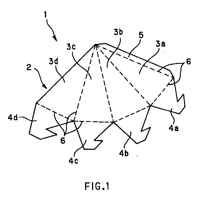
- Fig. 1 is a plan view showing one embodiment of the radio wave absorbent-assembling member of the present invention.
- radio wave absorbent-assembling member 1 comprises a radio wave absorptive thin material 2 which is capable of assembling a structure in a desired form.
- thin material 2 is capable of assembling a structure in the form of quadrangular pyramid, and comprises side plane members 3a, 3b, 3c and 3d which constitute the side planes of the quadrangular pyramid form, base plane members 4a, 4b, 4c and 4d which constitute the base plane, and joining member 5.
- thin material 2 has concave portions 6 (indicated by chain lines) for folding at the respective boundaries between the above-mentioned members.
- Each of the above-mentioned base plane members 4a, 4b, 4c and 4d has a form such that they are superposed on one another at the time of assembly to constitute the base plane.
- radio wave absorptive used in the present invention means to have a reflectivity of about -20 dB or less.
- thin material 2 which constitutes radio wave absorbent-assembling member 1 is any one of: (1) that which contains a conductive material therein; (2) that has on the surface thereof a conductive layer containing a conductive material; and (3) that which contains a conductive material therein and has on the surface thereof a conductive layer containing a conductive material.
- a non-combustible paper made from a slurry which contains an anhydrous inorganic compound and a conductive material.
- the thin material having the conductive layer mentioned in item (2) above can be produced by, for example, a method in which a conductive material is dispersed in an inorganic binder, to thereby prepare a conductive coating liquid, and in the prepared conductive coating liquid is immersed the above-mentioned non-combustible paper, the conventional non-combustible paper, or a plane plate thin material (a non-combustible board, a foamed polystyrol, a corrugated board or the like), followed by drawing out, to thereby form a conductive layer on the surface of the paper or plate; a method in which the surface of the above-mentioned non-combustible paper, the conventional non-combustible paper, or a plane plate thin material (a non-combustible board, a foamed polystyrol, a corrugated board or the like) is coated with the above-mentioned conductive coating liquid using a brush or the like, to thereby form a conductive conductive
- non-combustible used in the present invention means to be accepted by the constructional material test method (Notification No. 1828 of the Ministry of Construction) wherein a material which satisfies the requirement that when it is placed in a furnace at 750°C for 20 min, the increase in the inner temperature of the furnace be 50°C or less is judged as a non-combustible material.
- the conductive material used there is no particular limitation as long as it is conductive, and for example, carbon black, graphite, carbon fiber and the like can be used.
- carbon black, graphite, carbon fiber and the like can be used as examples of the above-mentioned inorganic binders.
- inorganic binders there can be mentioned a water glass, a silica-alumina and the like; however, the inorganic binders are not limited to these binders.
- the content of the conductive material in thin material 2 may be 5 to 80 g/m 2 , preferably 20 to 50 g/m 2 .
- the radio wave absorption properties of thin material 2 become unsatisfactory.
- the conductive material content is more than 80 g/m 2 , not only become the radio wave absorption properties at a frequency of about 20 MHz unsatisfactory, but also the thin material disadvantageously becomes unacceptable in the non-combustion test mentioned below due to a high calorific value.
- the content of the conductive material in thin material 2 may be adjusted every part within the above-mentioned range.
- the thickness of the above-mentioned thin material 2 may be 0.1 to 4 mm, preferably about 0.5 to 2 mm.
- the depth of concave portion 6 for folding may be 0.05 to 3 mm, preferably about 0.05 to 1 mm.
- Concave portion 6 for folding in thin material 2 may be formed by, for example, a method in which a die having a V-shaped cross-section is pushed, a method in which cutting is performed using a rotary blade, or the like.
- Figs. 2 are explanatory views illustrating the method for producing a radio wave absorbent using the radio wave absorbent-assembling member shown in Fig. 1 and the radio wave absorbent of the present invention.
- the method for producing a radio wave absorbent of the present invention comprises folding radio wave absorbent-assembling member 1 at concave portions 6 for folding in thin material 2 (see Fig. 2(A)), and joining together the end portions of side plane members 3a and 3d by bonding joining member 5 to the end portion of side plane member 3d (see Fig. 2(B)), and superposing base plane members 4a, 4b, 4c and 4d on one another and joining together to form a base plane (see Fig.
- radio wave absorbent 101 of the present invention see Fig. 2(D)
- the adhesive used in the assembly of such a structure in the form of quadrangular pyramid there can be used, for example, an adhesive cured by a hydration reaction, such as Portland cement and gypsum, or an inorganic adhesive, such as a phosphate, a silica sol and a water glass composition.
- a water glass composition which is inexpensive and has a high bonding property.
- Water glass is an aqueous solution which is mainly made of an alkali metal silicate, and sodium silicate is especially preferred because it is inexpensive and easily available as a product meeting Japanese Industrial Standard (JIS). Further, a mixture of a water glass of sodium silicate and that of lithium silicate may be used.
- a pedestal plate containing a conductive material and having a dielectric loss is arranged on the bottom portion of radio wave absorbent 101.
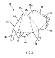
- Fig. 3 is a plan view showing another embodiment of the radio wave absorbent-assembling member of the present invention.
- radio wave absorbent-assembling member 11 comprises radio wave absorptive thin material 12 which is capable of assembling a structure in a desired form.
- thin material 12 is capable of assembling a structure in the form of wedge, and comprises oblique plane members 13a and 13c which constitute the oblique planes of the wedge form, side plane members 13b and 13d which constitute the side planes, base plane members 14a, 14b, 14c and 14d which constitute the base plane, and joining member 15.
- Each of the above-mentioned base plane members 14a, 14b, 14c and 14d has a form such that they are superposed on one another at the time of assembly to constitute the base plane.
- thin material 12 has concave portions 16 (indicated by chain lines) for folding at the respective boundaries between the above-mentioned members.
- the types of material and the thickness and the like can be selected similarly to those in the case of the above-mentioned thin material 2 of radio wave absorbent-assembling member 1. Therefore, an explanation about these is omitted here.
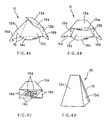
- Figs. 4 are explanatory views illustrating the method for producing a radio wave absorbent using the radio wave absorbent-assembling member shown in Fig. 3 and the radio wave absorbent of the present invention.
- the method for producing a radio wave absorbent of the present invention comprises folding radio wave absorbent-assembling member 11 at concave portions 16 for folding in thin material 12 (see Fig. 4(A)), and joining together the end portion of oblique plane member 13a and the end portion of side plane member 13d by bonding joining member 15 to the end portion of side plane member 13d (see Fig. 4(B)), and superposing base plane members 14a, 14b, 14c and 14d on one another and joining together to form a base plane (see Fig. 4(C)), to thereby obtain radio wave absorbent 111 in the form of wedge of the present invention (see Fig. 4 (D)).
- the adhesive used in the assembly the above-mentioned inorganic adhesives can be mentioned.
- the above-mentioned pedestal plate having a dielectric loss may also be arranged on the bottom portion of radio wave absorbent 111.
- radio wave absorbent-assembling member 21 comprises radio wave absorptive thin material 22 which is capable of assembling a structure in a desired form.
- thin material 22 is capable of assembling a structure in the form of quadrangular pyramid, and comprises side plane members 23a, 23b, 23c and 23d which constitute the side planes of the quadrangular pyramid form, connecting members 24a, 24b, 24c and 24d which connect the bases of the respective side planes, and joining member 25.
- Each of the above-mentioned connecting members 24a, 24b, 24c and 24d has a form such that they are superposed on one another at the time of assembly.
- thin material 22 has concave portions 26 (indicated by chain lines) for folding at the respective boundaries between the above-mentioned members.
- the types of material and the thickness and the like can be selected similarly to those in the case of the above-mentioned thin material 2 of radio wave absorbent-assembling member 1. Therefore, an explanation about these is omitted here.
- Figs. 6 are explanatory views illustrating the method for producing a radio wave absorbent using the radio wave absorbent-assembling member shown in Fig. 5 and the radio wave absorbent of the present invention.
- the method for producing a radio wave absorbent of the present invention comprises folding radio wave absorbent-assembling member 21 at concave portions 26 for folding in thin material 22 (see Fig. 6(A)), and joining together the end portions of side plane members 23a and 23d by bonding joining member 25 to the end portion of side plane member 23d (see Fig. 6(B)), and superposing connecting members 24a, 24b, 24c and 24d on one another and joining together (see Fig. 6(C)), to thereby obtain radio wave absorbent 121 of the present invention (see Fig. 6(D)).
- the adhesive used in the assembly of such a structure in the form of quadrangular pyramid the above-mentioned inorganic adhesives can be mentioned.
- the above-mentioned pedestal plate having a dielectric loss may also be arranged on the bottom portion of radio wave absorbent 121.
- Fig. 7 is a plan view showing another embodiment of the radio wave absorbent-assembling member of the present invention.
- radio wave absorbent-assembling member 31 comprises radio wave absorptive thin material 32 which is capable of assembling a structure in a desired form.
- thin material 32 is capable of assembling a structure in the form of quadrangular pyramid, and comprises side plane members 33a, 33b, 33c and 33d which constitute the side planes of the quadrangular pyramid form, and joining member 35.
- thin material 32 has concave portions 36 (indicated by chain lines) for folding at the respective boundaries between the above-mentioned members.
- the types of material and the thickness and the like can be selected similarly to those in the case of the above-mentioned thin material 2 of radio wave absorbent-assembling member 1. Therefore, an explanation about these is omitted here.
- Figs. 8 are explanatory views illustrating the method for producing a radio wave absorbent using the radio wave absorbent-assembling member shown in Fig. 7 and the radio wave absorbent of the present invention.
- the method for producing a radio wave absorbent of the present invention comprises folding radio wave absorbent-assembling member 31 at concave portions 36 for folding in thin material 32 (see Fig. 8(A)), and joining together the end portions of side plane members 33a and 33d by bonding joining member 35 to the end portion of side plane member 33d (see Fig. 8(B)), to thereby obtain radio wave absorbent 131 of the present invention (see Fig. 8(C)).
- the adhesive used in the assembly of such a structure in the form of quadrangular pyramid the above-mentioned inorganic adhesives can be mentioned.
- the above-mentioned pedestal plate having a dielectric loss may also be arranged on the bottom portion of radio wave absorbent 131.
- Fig. 9 is a plan view showing another embodiment of the radio wave absorbent-assembling member of the present invention.
- radio wave absorbent-assembling member 41 comprises radio wave absorptive thin material 42 which is capable of assembling a structure in a desired form.
- thin material 42 is capable of assembling a structure in the form of quadrangular pyramid, and comprises side plane members 43a, 43b, 43c and 43d which constitute the side planes of the quadrangular pyramid form, connecting members 44a, 44b, 44c and 44d which are used when a unit comprising a plurality of radio wave absorbents is formed as mentioned below, and joining member 45.
- thin material 42 has concave portions 46 (indicated by chain lines) for folding at the respective boundaries between the above-mentioned members.
- concave portions 46 indicated by chain lines
- the types of material and the thickness and the like can be selected similarly to those in the case of the above-mentioned thin material 2 of radio wave absorbent-assembling member 1. Therefore, an explanation about these is omitted here.
- Figs. 10 are explanatory views illustrating the method for producing a radio wave absorbent using the radio wave absorbent-assembling member shown in Fig. 9 and the radio wave absorbent of the present invention.
- the method for producing a radio wave absorbent of the present invention comprises folding radio wave absorbent-assembling member 41 at concave portions 46 for folding in thin material 42 (see Fig. 10(A)), and joining together the end portions of side plane members 43a and 43d by bonding joining member 45 to the end portion of side plane member 43d (see Fig. 10(B)), and folding outward connecting members 44a, 44b, 44c and 44d at concave portions 46, to thereby obtain radio wave absorbent 141 in the form of quadrangular pyramid of the present invention (see Fig. 10(C)).
- the adhesive used in the assembly the above-mentioned inorganic adhesives can be mentioned.
- the above-mentioned pedestal plate having a dielectric loss may also be arranged on the bottom portion of radio wave absorbent 141 without sacrificing the functions of connecting members 44a, 44b, 44c and 44d.
- the portion for folding in the radio wave absorbent-assembling members mentioned in the above first to fifth embodiments may have a reinforcing member.
- Fig. 11 is a plan view showing one example of the radio wave absorbent-assembling member of the present invention, in which radio wave absorbent-assembling member 1 shown in Fig. 1 has a reinforcing member.
- radio wave absorbent-assembling member 1' comprises reinforcing members 8 which are fixed on concave portions 6 using an inorganic adhesive.
- reinforcing member 8 there can be mentioned those which are formed into a sheet form using an inorganic adhesive, such as a fire-resistant fiber or a glass fiber.
- the inorganic adhesive used the above-mentioned inorganic adhesives can be mentioned.
- the radio wave absorbent mentioned in the above first to fifth embodiments may have a reinforcing member for reinforcing the tip portion.
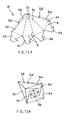
- Fig. 12 is a perspective view showing one example of the radio wave absorbent of the present invention, in which radio wave absorbent 101 shown in Figs. 2 has a reinforcing member.
- radio wave absorbent 101 in the form of quadrangular pyramid comprises reinforcing member 108 which is in the form of quadrangular pyramid (base plane is open) similar to radio wave absorbent 101 and fixed on the top portion of radio wave absorbent 101 using an inorganic adhesive.
- This reinforcing member 108 in the form of quadrangular pyramid can be produced by, for example, punching a sheet, which is formed from a fire-resistant fiber, a glass fiber or the like using an inorganic adhesive, into the form of radio wave absorbent-assembling member 31 shown in Fig. 7, and assembling the punched radio wave absorbent-assembling member using an inorganic adhesive.
- the inorganic adhesive used the above-mentioned inorganic adhesives can be mentioned.
- the joining member used for the radio wave absorbent-assembling member of the present invention is not limited to the embodiments described in the above-mentioned first to fifth embodiments.
- explanations on the joining member will be made, taking as an example radio wave absorbent-assembling member 1 shown in Fig. 1, with reference to Figs. 13 to 15.
- Radio wave absorbent-assembling member 1A shown in Figs. 13 is basically the same as radio wave absorbent-assembling member 1 shown in Fig. 1 except that the construction of joining member 5 is different.
- the joining member comprises joining member 5a which is provided on the end portion of side plane member 3a constituting the side plane at about half portion on the side of the base plane and joining member 5b which is provided on the end portion of side plane member 3d at about half portion on the side of the top portion (see Fig. 13(A)).
- Side end portions 5a' and 5b' on the side of the center of respective joining members 5a and 5b constitute a superposing portion having an acute angle tip.
- radio wave absorbent-assembling member 1A When radio wave absorbent-assembling member 1A is folded at concave portions 6 for folding to assemble a radio wave absorbent, at the joining of the end portion of side plane member 3a and the end portion of side plane member 3d, the above-mentioned joining members 5a and 5b respectively are secured by side end portions (superposing portions) 5a' and 5b' on the side of the center (see Fig. 13(B)). Therefore, the assembling operation is easy.
- Joining members 5a and 5b are preliminarily coated with an adhesive. Therefore, the setting of the adhesive progresses in a state such that the joining members are secured as mentioned above, so that joining member 5a is fixed on side plane member 3d and joining member 5b is fixed on side plane member 3a.
- Radio wave absorbent-assembling member 1B shown in Figs. 14 is basically the same as radio wave absorbent-assembling member 1 shown in Fig. 1 except that the construction of joining member 5 is different. Specifically, the joining member comprises base portion 5a and tip portion 5b having a width a little smaller than that of base portion 5a. On the other hand, around the end portion of side plane member 3d has notch portion 7 corresponding to the above-mentioned tip portion 5b (see Fig. 14(A)).
- radio wave absorbent-assembling member 1B When radio wave absorbent-assembling member 1B is folded at concave portions 6 for folding to assemble a radio wave absorbent, at the joining of the end portion of side plane member 3a and the end portion of side plane member 3d, tip portion 5b of joining member 5 which is preliminarily coated with an adhesive is inserted into notch portion 7 of side plane member 3d (see Fig. 14(B)), so that the end portion of side plane member 3a and the end portion of side plane member 3d are secured with each other (see Fig. 14(C)). Then, the setting of the adhesive progresses in a state such that the end portions are secured as mentioned above, so that base portion 5a of joining member 5 is fixed on side plane member 3d. Therefore, the assembling operation is easy.
- Radio wave absorbent-assembling member 1C shown in Figs. 15 is basically the same as radio wave absorbent-assembling member 1 shown in Fig. 1 except that the construction of joining member 5 is different.
- joining member 5 which is provided on the end portion of side plane member 3a constituting the side plane comprises three joining members 5A, 5B and 5C.
- Joining members 5A, 5B and 5C respectively comprise base portions 5a, 5b and 5c and tip portions 5a', 5b' and 5c' each having a width a litter smaller than that of the corresponding base portion.
- a plurality of the produced radio wave absorbents are connected to each other to form a single unit, and a frame member can be fixed for supporting on the periphery of the lower portion of the above unit.
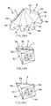
- Fig. 16 is a perspective view showing an example of the production of a radio wave absorbent as a unit by such a method.
- the base portions of the side planes of four radio wave absorbents 101 are connected to each other using four connecting members 203a, to thereby form a single unit.
- the unit is installed in frame member 202 in the corresponding form, and the base portions of the side planes of radio wave absorbents 101 and frame member 202 are connected to each other using eight connecting members 203b, to thereby obtain radio wave absorbent 201 as a single unit shown in Figs. 17 and 18.
- Fig. 18 is a longitudinal sectional view of the radio wave absorbent taken along the line A-A in Fig. 17.
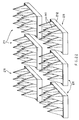
- Fig. 19 is a perspective view showing another example of the production of a radio wave absorbent as a unit.
- connecting members 44a, 44b, 44c and 44d of nine radio wave absorbents 141 are contacted with the surfaces or inner surfaces of adjacent radio wave absorbents 141, and adjacent radio wave absorbents 141 are connected to each other through the above connecting members 44a, 44b, 44c and 44d using an inorganic adhesive, to thereby form a single unit.
- Fig. 21 is a longitudinal sectional view of the radio wave absorbent taken along the line B-B in Fig. 20.
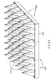
- radio wave absorbents 201 and 211 as a single unit are advantageous not only in that they can be handled unit by unit at the installation into the inner wall of an anechoic chamber, but also in that the individual radio wave absorbent is of lightweight, and hence, the handling is easy. Therefore, for example, the radio wave absorbent-assembling members of the present invention are carried in the construction site of an anechoic chamber, radio wave absorbents are individually produced from these radio wave absorbent-assembling members, and a plurality of units of radio wave absorbents 211 are produced from the above radio wave absorbents. Then, the plurality of units of radio wave absorbents 211 are arranged in the inner wall of the anechoic chamber as shown in Fig. 23, and frame members 212 are joined with each other.
- radio wave absorbent is not limited to the above two examples in which radio wave absorbents 101 and 141 are used as individual radio wave absorbents.
- a non-combustible board which contains a conductive material therein; (2) a non-combustible board which has on the surface thereof a conductive layer containing a conductive material; and (3) a non-combustible board which contains a conductive material therein and has on the surface thereof a conductive layer containing a conductive material.
- non-combustible board obtained by a method in which non-combustible sheets made from a slurry which contains a hydrous inorganic compound and a conductive material are laminated using an inorganic adhesive into a honeycomb form, to thereby obtain a honeycomb structure, and non-combustible sheets are disposed on both surfaces of the obtained honeycomb structure, from the viewpoints of the radio wave absorption properties, the weight reduction, the non-combustibility, the mechanical strength and the heat dissipation properties.
- a non-combustible sheet is made from a slurry which contains a hydrous inorganic compound and, if desired, a conductive material, the non-combustible sheet is coated with an inorganic adhesive in a line form at the predetermined interval in the lengthwise direction of the sheet while shifting the coating position of the inorganic adhesive in a line form by a half pitch between the adjacent non-combustible sheets, followed by lamination of a predetermined number of the non-combustible sheets.
- the resultant laminate is pressed so that the sheets are joined together at inorganic adhesive coating sites, to thereby obtain a sheet block.
- the coating width of the above inorganic adhesive corresponds to the length of the lamination surface of the cell of the honeycomb structure, and the cell size can be controlled by adjusting the width and the formation interval of the inorganic adhesive layer.
- the above-obtained sheet block is cut out so that the thickness of a honeycomb structure becomes a desired value, and immersed in an inorganic impregnating agent, to thereby allow the cut-out sheet to expand.
- the inorganic impregnating agent is dried and set in a desired expansion state such that a desired cell can be formed, to form an inorganic impregnating agent layer, thereby obtaining a honeycomb structure.
- the above-mentioned non-combustible sheets are arranged on both surfaces of the obtained honeycomb structure using an inorganic adhesive.
- the inorganic binder used there can be mentioned, for example, an aqueous solution or an aqueous dispersion comprising an aluminum phosphate solution, a colloidal silica, a colloidal alumina or the like having mixed therewith a curing agent, a catalyst and the like.
- the inorganic impregnating agent various types of inorganic adhesives can be used, and it is preferred that the same inorganic adhesive as that used for joining the non-combustible sheet is used.
- each of the above-mentioned frame members 202 and 212 can be adjusted in the range of from about 3 to 200 mm.
- connecting members 203a and 203b used in the production of the above units of radio wave absorbents 201 and 211 there can be mentioned those which are formed into a sheet form using an inorganic adhesive, such as a fire-resistant fiber or a glass fiber.
- an inorganic adhesive such as a fire-resistant fiber or a glass fiber.
- the adhesive used the above-mentioned inorganic adhesives can be mentioned.
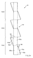
- Fig. 24 is a plan view showing another embodiment of the radio wave absorbent-assembling member of the present invention.
- radio wave absorbent-assembling member 51 comprises radio wave absorptive thin material 52 which is capable of assembling a structure in a desired form.
- thin material 52 comprises three units 52A which are connected, and is capable of assembling a structure which comprises a three wedge forms connected.
- single assembly unit 52A comprises oblique plane members 53a and 53b which constitute the oblique planes of the wedge form, side plane members 53c and 53d which constitute the side planes, and joining members 55a and 55b which are respectively provided in the end portions of side plane members 53c and 53d, and three assembly units 52A are connected.
- each of assembly units 52A has concave portions 56 (indicated by chain lines) for folding at the respective boundaries between the above-mentioned members
- thin material 52 has concave portions 56 (indicated by chain lines) for folding at the respective boundaries between the above-mentioned units.
- thin material 52 the types of material and the thickness and the like can be selected similarly to those in the case of the above-mentioned thin material 2 of radio wave absorbent-assembling member 1. Therefore, an explanation about these is omitted here.
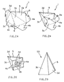
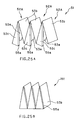
- Figs. 25 are explanatory views illustrating the method for producing a radio wave absorbent using the radio wave absorbent-assembling member shown in Fig. 24 and the radio wave absorbent of the present invention.
- the method for producing a radio wave absorbent of the present invention comprises folding radio wave absorbent-assembling member 51 at concave portions 56 for folding in thin material 52 (see Fig. 25(A)), and respectively joining the end portions of oblique plane members 53a and 53b to the end portions of side plane members 53d and 53c by respectively bonding joining members 55b and 55a to the end portions of oblique plane members 53a and 53b, to thereby obtain radio wave absorbent 151 in the form of wedge of the present invention (see Fig. 25(B)).
- radio wave absorbent 151 in the form of wedge is a structure which comprises three wedge forms connected as shown in these figures.
- the adhesive used in the assembly the above-mentioned inorganic adhesives can be mentioned.
- a plurality of the above radio wave absorbents 151 are connected to each other to form a single unit, and a frame member can be fixed for supporting on the periphery of the lower portion of the above unit.
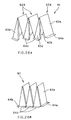
- Figs. 26 are perspective views showing an example of the production of a radio wave absorbent as a unit by such a method.
- two radio wave absorbents 151 are connected to each other using an inorganic adhesive at the side planes (planes indicated by diagonal solid lines with respect to one side of radio wave absorbents 151) of the opposite radio wave absorbents 151, to thereby form a single unit.
- the unit is installed in frame member 222 in the corresponding form.
- the base portions of the oblique planes of radio wave absorbents 151 and frame member 222 are connected to each other using four connecting members 223, and the base portions of the side planes of radio wave absorbents 151 (planes indicated by diagonal chain lines with respect to one side of radio wave absorbents 151) and frame member 222 are connected to each other using an inorganic adhesive (see Fig. 26(A)), to thereby obtain radio wave absorbent 221 as a single unit shown in Fig. 26(B).
- Frame member 222 and connecting member 223 are respectively similar to frame member 202 or 212 and connecting member 203a or 203b. Therefore, an explanation about these is omitted here.
- the portion for folding of the radio wave absorbent-assembling member may have a reinforcing member and the tip portion of the individual radio wave absorbent may also have a reinforcing member, and joining members 55a and 55b can be in various forms mentioned above.
- the above-mentioned pedestal plate may also be arranged on the bottom portion of radio wave absorbent 221.
- Fig. 27 is a plan view showing another embodiment of the radio wave absorbent-assembling member of the present invention.
- radio wave absorbent-assembling member 61 comprises radio wave absorptive thin material 62 which is capable of assembling a structure in a desired form.
- thin material 62 comprises three units 62A which are connected, and is capable of assembling a structure which comprises a three wedge forms connected.
- single assembly unit 62A comprises oblique plane members 63a and 63b which constitute the oblique planes of the wedge form, side plane members 63c and 63d which constitute the side planes, joining members 65a and 65b which are respectively provided in the end portions of side plane members 63c and 63d, and fixing members 64c and 64d which are respectively provided in side plane members 63c and 63d, and three assembly units 62A are connected.
- the end portions of thin material 62 have fixing members 64a and 64b.
- each of assembly units 62A has concave portions 66 (indicated by chain lines) for folding at the respective boundaries between the above-mentioned members
- thin material 62 has concave portions 66 (indicated by chain lines) for folding at the respective boundaries between the above-mentioned units.
- thin material 62 the types of material and the thickness and the like can be selected similarly to those in the case of the above-mentioned thin material 2 of radio wave absorbent-assembling member 1. Therefore, an explanation about these is omitted here.
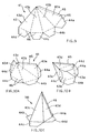
- Figs. 28 are explanatory views illustrating the method for producing a radio wave absorbent using the radio wave absorbent-assembling member shown in Fig. 27 and the radio wave absorbent of the present invention.
- the method for producing a radio wave absorbent of the present invention comprises folding radio wave absorbent-assembling member 61 at concave portions 66 for folding in thin material 62 (see Fig.
- radio wave absorbent 161 in the form of wedge is a structure which comprises three wedge forms connected as shown in these figures.
- adhesive used in the assembly the above-mentioned inorganic adhesives can be mentioned.
- a plurality of the above radio wave absorbents 161 are connected to each other to form a single unit, and a frame member can be fixed for supporting on the periphery of the bottom portion of the above unit.
- Figs. 29 are perspective views showing an example of the production of a radio wave absorbent as a unit by such a method.
- two radio wave absorbents 161 are connected to each other using an inorganic adhesive at the side planes (planes indicated by diagonal solid lines with respect to one side of radio wave absorbents 161) of the opposite radio wave absorbents 161, to thereby form a single unit.
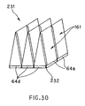
- supporting material 232 comprising base plate 233 made in the form corresponding to the base plane of the obtained unit and six reinforcing plates 234 disposed on base plate 233 are provided (see Fig. 29(A)).
- the unit comprising two radio wave absorbents 161 is installed on supporting material 232 so that reinforcing plates 234 are respectively inserted into the structures in the form of wedge (see Fig. 29(B)).
- the fixing members 64a, 64b, 64c and 64d of radio wave absorbents 161 are fixed on side plane 233a of base plate 233 using an inorganic adhesive, to thereby obtain radio wave absorbent 231 as a single unit shown in Fig. 30.
- Supporting material 232 can be produced from a laminate of a non-combustible paper, or a non-combustible board.
- the non-combustible paper there can be used one that is made from a slurry which contains a hydrous inorganic compound.
- the non-combustible board there can be used a non-combustible board having a honeycomb structure prepared using a non-combustible sheet made from a slurry which contains a hydrous inorganic compound in the same procedure as that described in connection with the above frame members 202 and 212.
- the portion for folding of the radio wave absorbent-assembling member may have a reinforcing member and the tip portion of the individual radio wave absorbent may also have a reinforcing member, and joining members 65a and 65b can be in various forms mentioned above.
- a slurry for a non-combustible paper having the composition described below was prepared using a Henschel mixer.
- Sepiolite (Aidplus, manufactured and sold by Mizusawa Chemical Industries, Co., Ltd.): 60 Parts by weight Glass fiber (6 mm product, manufactured and sold by Nitto Boseki Co., Ltd.): 7 Parts by weight Graphite (Blue P, manufactured and sold by Nippon Kokuen Co., Ltd.) 30 Parts by weight Organic binder 3 Parts by weight
- a non-combustible paper (thickness: 0.7 mm) as a thin material containing a conductive material was made, and a radio wave absorbent-assembling member in the form shown in Fig. 1 was prepared.
- the content of the conductive material in the prepared radio wave absorbent-assembling member was 78 g/m 2 .
- the above radio wave absorbent-assembling member had concave portions for folding (depth: 0.08 mm).
- a radio wave absorbent was prepared as follows.
- the radio wave absorbent-assembling member was folded at the concave portions for folding as shown in Figs. 2, and the end portions of the side planes were joined together to form a base plane, to thereby prepare a radio wave absorbent in the form of quadrangular pyramid (height: 900 mm; length of the base: 200 mm).
- the same nine radio wave absorbents were prepared.
- a test was performed in accordance with the method for a non-combustible material prescribed in Notification No. 1828 of the Ministry of Construction.
- the radio wave absorbents were laminated using an inorganic adhesive (FJ294, manufactured and sold by Tokiwa Electric Co., Ltd.), to thereby prepare a test specimen having a size of 40 mm x 40 mm x 50 mm.
- the test specimen was heated in a furnace at 750 ⁇ 10°C for 20 min, and the increase in the temperature of the specimen by heating was measured. When the increase in the temperature of the specimen by heating is less than 50°C, the non-combustibility of this specimen is acceptable.
- ferrite IB-011 thickness: 6.9 mm
- TDK Corporation ferrite IB-011 (thickness: 6.9 mm) (manufactured and sold by TDK Corporation) having a shield panel on the back surface thereof was fitted on the base plane of the above radio wave absorbent, and a radio wave absorbing ability at 1 GHz was measured.
- radio wave absorbent 80 was subjected to radio wave irradiation, and a reflection wave level was measured.
- transmitting antenna 83 and receiving antenna 84 are arranged with screen 82 between, and to transmitting antenna 83 is connected S-parameter 85, and receiving antenna 84 is connected through RF amplifier 86 to the above S-parameter 85.
- S-parameter 85 is connected through network analyzer 87 to measurement controller 88, and to this measurement controller 88 is connected printer 89.
- the reflectivity (dB) of a radio wave absorbent was calculated using, as a reference, the reflection level of a metal plate having the same size (600 mm x 600 mm) as that of the base plane of the unit comprising nine radio wave absorbents by the following formula, and the results are shown in Table 1.
- Reflectivity (dB) Reflection level (dB) of radio wave absorbent - Reflection level (dB) of metal plate
- a slurry for a non-combustible paper having the composition described below was prepared using a Henschel mixer.
- Sepiolite (Aidplus, manufactured and sold by Mizusawa Chemical Industries, Co., Ltd.): 80 Parts by weight Glass fiber (6 mm product, manufactured and sold by Nitto Boseki Co., Ltd.): 15 Parts by weight Organic binder 5 Parts by weight
- a conductive coating liquid having the composition described below was prepared using a Henschel mixer.
- a radio wave absorbent-assembling member in the form shown in Fig. 1 was prepared.
- the content of the conductive material in the prepared radio wave absorbent-assembling member was 45 g/m 2 .
- the above radio wave absorbent-assembling member had concave portions for folding (depth: 0.08 mm).
- radio wave absorbent-assembling member nine radio wave absorbents in the form of quadrangular pyramid (height: 900 mm; length of the base: 200 mm) in which the conductive coating liquid coated surface was arranged as the surface of the radio wave absorbent were prepared in the same manner as in Example 1.
- a non-combustible paper (thickness: 0.7 mm) was made in the same manner as in Example 2.
- a conductive coating liquid having the composition described below was prepared using a Henschel mixer.
- Carbon black (EC, manufactured and sold by Kechen Black Co., Ltd.) 10 Parts by weight Inorganic coating agent (FJ803, manufactured and sold by Tokiwa Electric Co., Ltd.) 90 Parts by weight
- a radio wave absorbent-assembling member in the form shown in Fig. 1 was prepared.
- the content of the conductive material in the prepared radio wave absorbent-assembling member was 7 g/m 2 .
- the above radio wave absorbent-assembling member had concave portions for folding (depth: 0.08 mm).
- radio wave absorbent-assembling member nine radio wave absorbents in the form of quadrangular pyramid (height: 900 mm; length of the base: 200 mm) in which the conductive coating liquid coated surface was arranged as the surface of the radio wave absorbent were prepared in the same manner as in Example 1.
- a non-combustible paper (thickness: 0.7 mm) was made in the same manner as in Example 2.
- a conductive coating liquid was prepared using a Henschel mixer in the same manner as in Example 2.
- a radio wave absorbent-assembling member in the form shown in Fig. 24 was prepared.
- the content of the conductive material in the prepared radio wave absorbent-assembling member was 48 g/m 2 .
- the above radio wave absorbent-assembling member had concave portions for folding (depth: 0.08 mm).
- radio wave absorbent-assembling member using the above radio wave absorbent-assembling member and an inorganic adhesive (a mixture of potassium silicate and diantimony pentaoxide), a radio wave absorbent in which the conductive coating liquid coated surface was arranged as the surface of the radio wave absorbent and three wedge forms were connected (with respect to one wedge form, the height was 900 mm, the tip width was 300 mm, and the base plane was 200 mm x 300 mm) was prepared. The same two radio wave absorbents were prepared.
- an inorganic adhesive a mixture of potassium silicate and diantimony pentaoxide
- a non-combustible paper (thickness: 0.7 mm) was made in the same manner as in Example 2.
- a conductive coating liquid was prepared using a Henschel mixer in the same manner as in Example 2.
- a radio wave absorbent-assembling member in the form shown in Fig. 24 was prepared.
- the content of the conductive material in the prepared radio wave absorbent-assembling member was adjusted so that, with respect to each wedge form of the below-mentioned radio wave absorbent comprising three wedge forms connected, the conductive material contents of the 1/3 height portions from the side of the radio wave irradiation source (tip side) became 15 g/m 2 , 30 g/m 2 and 45 g/m 2 , respectively.
- the above radio wave absorbent-assembling member had concave portions for folding (depth: 0.08 mm).
- radio wave absorbent-assembling member and an inorganic adhesive (a mixture of potassium silicate and diantimony pentaoxide)
- an inorganic adhesive a mixture of potassium silicate and diantimony pentaoxide
- two radio wave absorbents were prepared in the same manner as in Example 4, in which the conductive coating liquid coated surface was arranged as the surface of the radio wave absorbent and three wedge forms were connected (with respect to one wedge form, the height was 900 mm, the tip width was 300 mm, and the base plane was 200 mm x 300 mm) was prepared.
- a non-combustible paper (thickness: 0.7 mm) was made in the same manner as in Example 2.
- a conductive coating liquid was prepared using a Henschel mixer in the same manner as in Example 2.
- a radio wave absorbent-assembling member in the form shown in Fig. 1 was prepared.
- the content of the conductive material in the prepared radio wave absorbent-assembling member was 3 g/m 2 .
- the above radio wave absorbent-assembling member had concave portions for folding (depth: 0.08 mm).
- radio wave absorbent-assembling member nine radio wave absorbents in the form of quadrangular pyramid (height: 900 mm; length of the base: 200 mm) in which the conductive coating liquid coated surface was arranged as the surface of the radio wave absorbent were prepared in the same manner as in Example 1.
- a non-combustible paper (thickness: 0.7 mm) was made in the same manner as in Example 2.
- a conductive coating liquid was prepared using a Henschel mixer in the same manner as in Example 2.
- a radio wave absorbent-assembling member in the form shown in Fig. 1 was prepared.
- the content of the conductive material in the prepared radio wave absorbent-assembling member was 82 g/m 2 .
- the above radio wave absorbent-assembling member had concave portions for folding (depth: 0.08 mm).
- radio wave absorbent-assembling member nine radio wave absorbents in the form of quadrangular pyramid (height: 900 mm; length of the base: 200 mm) in which the conductive coating liquid coated surface was arranged as the surface of the radio wave absorbent were prepared in the same manner as in Example 1.
- the radio wave absorbing ability of the radio wave absorbent prepared in Comparative Example 1 is unsatisfactory.
- the radio wave absorbent prepared in Comparative Example 2 has excellent radio wave absorbing ability; however, this radio wave absorbent has a poor non-combustibility, as compared with the radio wave absorbents prepared in Examples.
Landscapes
- Shielding Devices Or Components To Electric Or Magnetic Fields (AREA)
- Building Environments (AREA)
Abstract
Description
| Sepiolite (Aidplus, manufactured and sold by Mizusawa Chemical Industries, Co., Ltd.): | 60 Parts by weight |
| Glass fiber (6 mm product, manufactured and sold by Nitto Boseki Co., Ltd.): | 7 Parts by weight |
| Graphite (Blue P, manufactured and sold by Nippon Kokuen Co., Ltd.) | 30 Parts by weight |
| Organic binder | 3 Parts by weight |
| Sepiolite (Aidplus, manufactured and sold by Mizusawa Chemical Industries, Co., Ltd.): | 80 Parts by weight |
| Glass fiber (6 mm product, manufactured and sold by Nitto Boseki Co., Ltd.): | 15 Parts by weight |
| |
5 Parts by weight |
| Graphite ( |
20 Parts by weight |
| Inorganic coating agent (FJ803, manufactured and sold by Tokiwa Electric Co., Ltd.) | 80 Parts by weight |
| Carbon black (EC, manufactured and sold by Kechen Black Co., Ltd.) | 10 Parts by weight |
| Inorganic coating agent (FJ803, manufactured and sold by Tokiwa Electric Co., Ltd.) | 90 Parts by weight |
| Radio Wave Absorbent | Non-Combustibility | Reflectivity (dB) |
| Example 1 | Good (797°C) | -32 |
| Example 2 | Good (778°C) | -28 |
| Example 3 | Good (765°C) | -21 |
| Example 4 | Good (778°C) | -24 |
| Example 5 | Good (770°C) | -30 |
| Comparative Example 1 | Good (763°C) | -12 |
| Comparative Example 2 | Poor (812°C) | -34 |
| *Note: The figures given in parentheses "()" at the column of "NON-COMBUSTIBILITY' indicates temperature values of the heated test specimens. |
Claims (24)
- A radio wave absorbent-assembling member comprising a radio wave absorptive thin material capable of assembling a structure in a desired form, wherein said thin material (2) contains a conductive material therein and/or has on the surface thereof a conductive layer containing a conductive material.
- The radio wave absorbent-assembling member according to claim 1, wherein said thin material (2) has a concave portion (6) for folding.
- The radio wave absorbent-assembling member according to claim 1 or 2, wherein said thin material (2) contains a conductive material in the range of from 5 to 80 g/m2.
- The radio wave absorbent-assembling member according to claims 1 to 3, wherein said thin material (2) is a non-combustible paper made from a slurry which contains a hydrous inorganic compound.
- The radio wave absorbent-assembling member according to claims 1 to 4, wherein said conductive material comprises at least one substance selected from the group consisting of carbon black and graphite.
- The radio wave absorbent-assembling member according to claims 1 to 5, which is capable of assembling a plurality of structures which are connected to each other.
- A radio wave absorbent formed using a radio wave absorbent-assembling member, which is a structure formed by folding said radio wave absorbent-assembling member which comprises a radio wave absorptive thin material capable of assembling a structure in a desired form and joining together the end portions of the folded radio wave absorbent-assembling member, wherein said thin material (2) contains a conductive material therein and/or has on the surface thereof a conductive layer containing a conductive material.
- The radio wave absorbent according to claim 7, wherein said structure is in the form of any one of wedge and quadrangular pyramid.
- The radio wave absorbent according to claim 7 or 8, which comprises a plurality of structures (101) which are connected to each other and a frame member (202) fixed on the periphery of the lower portion of said plurality of structures (101).
- The radio wave absorbent according to claim 7 or 8, which comprises a plurality of structures (161) which are connected to each other and a supporting material (232) fixed on the periphery of the bottom portion of said plurality of structures (161).
- The radio wave absorbent according to claims 7 to 10, wherein said thin material (2) has a concave portion (6) for folding.
- The radio wave absorbent according to claims 7 to 11, wherein said thin material (2) contains a conductive material in the range of from 5 to 80 g/m2.
- The radio wave absorbent according to claims 7 to 12, wherein said thin material (2) is a non-combustible paper made from a slurry which contains a hydrous inorganic compound.
- The radio wave absorbent according to claims 7 to 13, wherein said conductive material comprises at least one substance selected from the group consisting of carbon black and graphite.
- A method for producing a radio wave absorbent, which comprises:processing a thin material (2) into a form which is capable of assembling a structure in a desired form, to thereby prepare a radio wave absorbent-assembling member (1), wherein said thin material (2) contains a conductive material therein and/or has on the surface thereof a conductive layer containing a conductive material; andfolding said radio wave absorbent-assembling member (1) and joining together the end portions of the folded radio wave absorbent-assembling member.
- The method for producing a radio wave absorbent according to claim 15, wherein said radio wave absorbent is in the form of any one of wedge, quadrangular pyramid and triangular prism.
- The method for producing a radio wave absorbent according to claim 15 or 16, which further comprises: preliminarily forming a concave portion (6) for folding in said thin material (2), wherein said thin material (2) is folded at said concave portion (6).
- The method for producing a radio wave absorbent according to claims 15 to 17, which further comprises: connecting a plurality of said radio wave absorbents (101) to each other, to thereby form a single unit; and fixing a frame member (202) for supporting on the periphery of the lower portion of said unit.
- The method for producing a radio wave absorbent according to claim 18, wherein said frame member (202) is a non-combustible board which contains a conductive material therein and/or has on the surface thereof a conductive layer containing a conductive material.
- The method for producing a radio wave absorbent according to claim 19, wherein said non-combustible board is obtained by a method in which non-combustible sheets made from a slurry which contains a hydrous inorganic compound are laminated using an inorganic adhesive into a honeycomb form, to thereby obtain a honeycomb structure, and non-combustible sheets are disposed on both the surfaces of the obtained honeycomb structure.
- The method for producing a radio wave absorbent according to claims 15 to 17, which further comprises: connecting a plurality of said radio wave absorbents (161) to each other, to thereby form a single unit; and fixing a supporting material (232) for supporting on the periphery of the bottom portion of said unit.
- The method for producing a radio wave absorbent according to claim 21, wherein said supporting material (232) is any one of a laminate of a non-combustible paper and a non-combustible board.
- The method for producing a radio wave absorbent according to claim 22, wherein said non-combustible paper is a non-combustible paper made from a slurry which contains a hydrous inorganic compound.
- The method for producing a radio wave absorbent according to claim 22, wherein said non-combustible board is obtained by a method in which non-combustible sheets made from a slurry which contains a hydrous inorganic compound are laminated using an inorganic adhesive into a honeycomb form, to thereby obtain a honeycomb structure, and non-combustible sheets are disposed on both the surfaces of the obtained honeycomb structure.
Applications Claiming Priority (2)
| Application Number | Priority Date | Filing Date | Title |
|---|---|---|---|
| JP1332699 | 1999-01-21 | ||
| JP01332699A JP4377467B2 (en) | 1999-01-21 | 1999-01-21 | Radio wave absorber assembly member and radio wave absorber using the same |
Publications (3)
| Publication Number | Publication Date |
|---|---|
| EP1022805A2 true EP1022805A2 (en) | 2000-07-26 |
| EP1022805A3 EP1022805A3 (en) | 2002-06-19 |
| EP1022805B1 EP1022805B1 (en) | 2004-11-24 |
Family
ID=11830040
Family Applications (1)
| Application Number | Title | Priority Date | Filing Date |
|---|---|---|---|
| EP00101204A Expired - Lifetime EP1022805B1 (en) | 1999-01-21 | 2000-01-21 | Radio wave absorbent-assembling member, radio wave absorbent and method for producing the same |
Country Status (6)
| Country | Link |
|---|---|
| US (1) | US6407693B1 (en) |
| EP (1) | EP1022805B1 (en) |
| JP (1) | JP4377467B2 (en) |
| KR (1) | KR100472198B1 (en) |
| DE (1) | DE60016056T2 (en) |
| TW (1) | TW533761B (en) |
Cited By (2)
| Publication number | Priority date | Publication date | Assignee | Title |
|---|---|---|---|---|
| WO2004060037A1 (en) * | 2002-12-25 | 2004-07-15 | Toray Industries, Inc. | Sheet material for radio wave-absorbing body and radio wave-absorbing body |
| CN119115461A (en) * | 2024-11-12 | 2024-12-13 | 中国机械总院集团江苏分院有限公司 | Processing method of wave-absorbing pyramid based on honeycomb material |
Families Citing this family (14)
| Publication number | Priority date | Publication date | Assignee | Title |
|---|---|---|---|---|
| JP4299387B2 (en) * | 1998-10-05 | 2009-07-22 | Tdk株式会社 | Radio wave absorber assembly member and radio wave absorber manufacturing method |
| JP2003229691A (en) * | 2002-01-31 | 2003-08-15 | Riken Corp | Radio wave absorber |
| CN100484384C (en) * | 2002-12-25 | 2009-04-29 | 东丽株式会社 | Sheet material for radio wave-absorbing body and radio wave-absorbing body |
| TWI374007B (en) | 2004-03-22 | 2012-10-01 | Toray Industries | Electromagnetic wave absorbing sheet material and electromagnetic wave absorbin body using it |
| JP4144754B2 (en) * | 2004-05-31 | 2008-09-03 | Tdk株式会社 | Radio wave absorber |
| JP4825074B2 (en) * | 2005-08-05 | 2011-11-30 | Tdk株式会社 | Radio wave absorber, method for manufacturing the same, and anechoic chamber |
| US7479917B2 (en) | 2005-08-05 | 2009-01-20 | Tdk Corporation | Electromagnetic wave absorber, manufacturing method thereof and electromagnetic wave anechoic room |
| EP2672219A1 (en) * | 2011-02-03 | 2013-12-11 | Nireco Corporation | Width-direction end position measuring device for band-shaped member, width-direction center position measuring device for band-shaped member, and microwave scattering plate |
| JP5953798B2 (en) * | 2011-02-22 | 2016-07-20 | 東レ株式会社 | Sheet material for radio wave absorber and radio wave absorber |
| JP5953799B2 (en) * | 2011-02-22 | 2016-07-20 | 東レ株式会社 | Sheet material for radio wave absorber and radio wave absorber |
| KR101826355B1 (en) * | 2011-08-22 | 2018-02-07 | 한국전자통신연구원 | Electromagnetic wave reverberation chamber |
| KR102425862B1 (en) * | 2021-03-30 | 2022-07-27 | 국방과학연구소 | Wave absorber allowing fluid flow and aircraft comprising the same |
| KR102558275B1 (en) * | 2023-01-30 | 2023-07-21 | 국방과학연구소 | Manufacturing system for radio wave absorber for high temperature |
| KR102562499B1 (en) * | 2023-02-14 | 2023-08-02 | 국방과학연구소 | Manufacturing method of honeycomb composite structure for absorbing electromagnetic waves using screen printing and honeycomb composite structure manufactured by the manufacturing method |
Family Cites Families (15)
| Publication number | Priority date | Publication date | Assignee | Title |
|---|---|---|---|---|
| JP2760578B2 (en) | 1989-07-03 | 1998-06-04 | アクゾ・カシマ株式会社 | Manufacturing method of radio wave absorber |
| JPH0399496A (en) * | 1989-09-12 | 1991-04-24 | Gureesu Japan Kk | Radio wave absorber |
| DE4215954A1 (en) * | 1992-02-04 | 1993-08-05 | Rheinhold & Mahla Ag | Electromagnetic wave absorber in closed and screened spaces - has pyramidal frame and filling constituted by plastic foam impregnated with carbon, metal oxide or mixt. |
| US5373296A (en) * | 1992-08-18 | 1994-12-13 | Tdk Corporation | Electromagnetic wave absorber and wave absorption structure |
| CA2163516C (en) | 1993-06-25 | 1999-07-13 | Gunter Nimtz | System for absorbing electromagnetic waves and method of manufacturing this system |
| JP3394848B2 (en) * | 1994-06-23 | 2003-04-07 | 株式会社竹中工務店 | Radio wave absorber member, radio wave absorber, and method of manufacturing radio wave absorber member |
| JPH0883992A (en) * | 1994-09-12 | 1996-03-26 | Natl Space Dev Agency Japan<Nasda> | Radio wave absorber |
| JPH09275295A (en) | 1996-04-05 | 1997-10-21 | Nec Corp | Radio wave absorber |
| JPH09307268A (en) | 1996-05-13 | 1997-11-28 | Tohoku Kako Kk | Radio wave absorber |
| JP3564234B2 (en) | 1996-07-29 | 2004-09-08 | 宇宙開発事業団 | Blade antenna mounting device |
| JPH10163670A (en) | 1996-11-29 | 1998-06-19 | Mitsubishi Chem Corp | Manufacturing method of quadrangular pyramidal radio wave absorber |
| JPH10217217A (en) * | 1997-02-07 | 1998-08-18 | Mitsubishi Chem Corp | Manufacturing method of cone wave absorber |
| TW410542B (en) * | 1997-03-14 | 2000-11-01 | Hitachi Maxell | Wave absorber |
| JPH1187978A (en) * | 1997-09-09 | 1999-03-30 | Nitto Boseki Co Ltd | Non-combustible radio wave absorber |
| JP4299387B2 (en) * | 1998-10-05 | 2009-07-22 | Tdk株式会社 | Radio wave absorber assembly member and radio wave absorber manufacturing method |
-
1999
- 1999-01-21 JP JP01332699A patent/JP4377467B2/en not_active Expired - Fee Related
-
2000
- 2000-01-18 TW TW089100754A patent/TW533761B/en not_active IP Right Cessation
- 2000-01-20 US US09/487,613 patent/US6407693B1/en not_active Expired - Fee Related
- 2000-01-20 KR KR10-2000-0002562A patent/KR100472198B1/en not_active Expired - Fee Related
- 2000-01-21 DE DE60016056T patent/DE60016056T2/en not_active Expired - Lifetime
- 2000-01-21 EP EP00101204A patent/EP1022805B1/en not_active Expired - Lifetime
Cited By (3)
| Publication number | Priority date | Publication date | Assignee | Title |
|---|---|---|---|---|
| WO2004060037A1 (en) * | 2002-12-25 | 2004-07-15 | Toray Industries, Inc. | Sheet material for radio wave-absorbing body and radio wave-absorbing body |
| US7695803B2 (en) | 2002-12-25 | 2010-04-13 | Toray Industries, Inc. | Sheet material for radio wave absorber and radio wave absorber |
| CN119115461A (en) * | 2024-11-12 | 2024-12-13 | 中国机械总院集团江苏分院有限公司 | Processing method of wave-absorbing pyramid based on honeycomb material |
Also Published As
| Publication number | Publication date |
|---|---|
| EP1022805A3 (en) | 2002-06-19 |
| JP4377467B2 (en) | 2009-12-02 |
| EP1022805B1 (en) | 2004-11-24 |
| JP2000216584A (en) | 2000-08-04 |
| TW533761B (en) | 2003-05-21 |
| KR20000062487A (en) | 2000-10-25 |
| DE60016056T2 (en) | 2005-11-03 |
| US6407693B1 (en) | 2002-06-18 |
| DE60016056D1 (en) | 2004-12-30 |
| KR100472198B1 (en) | 2005-03-07 |
Similar Documents
| Publication | Publication Date | Title |
|---|---|---|
| EP1022805B1 (en) | Radio wave absorbent-assembling member, radio wave absorbent and method for producing the same | |
| KR100333568B1 (en) | Incombustible honeycomb radio absorptive material and radio absorber using the same | |
| US5932054A (en) | Radio wave absorber composition, radio wave absorber member, radio wave absorber, and method for producing radio wave absorber member | |
| US6613975B1 (en) | Member for assembling radio wave absorber and method of producing radio wave absorber | |
| JP2004270143A (en) | Radio wave absorber, radio wave absorbing panel, radio wave absorbing screen, radio wave absorbing wall, radio wave absorbing ceiling, and radio wave absorbing floor | |
| JPH03130472A (en) | Manufacture of surface member for absorbing electromagnetic wave | |
| KR20000022855A (en) | Electric wave absorber | |
| EP0989797B1 (en) | Radio wave transmitting material | |
| JP2786471B2 (en) | Fireproof composite panel | |
| JPH01220899A (en) | Wave absorber and manufacture thereof | |
| JP2814119B2 (en) | Radio wave absorbing material, method of manufacturing the same, and radio wave absorbing plate using the radio wave absorbing material | |
| KR101102643B1 (en) | Electromagnetic wave absorption sheet material and electromagnetic wave absorber using same | |
| JP3131609B2 (en) | Radio wave absorber | |
| JP3615135B2 (en) | Electromagnetic wave absorber | |
| JP2000135752A (en) | Electric wave transmitting object | |
| JP2008130749A (en) | Nonflammable wave absorber | |
| JP2804716B2 (en) | Radio wave absorption panel | |
| JPS6035697Y2 (en) | architectural board | |
| JPH0227798A (en) | Radio wave absorber and its manufacture | |
| JP2004119855A (en) | Electromagnetic wave absorber | |
| JP2000144971A (en) | Electric wave-absorbing soundproof panel for building material |
Legal Events
| Date | Code | Title | Description |
|---|---|---|---|
| PUAI | Public reference made under article 153(3) epc to a published international application that has entered the european phase |
Free format text: ORIGINAL CODE: 0009012 |
|
| AK | Designated contracting states |
Kind code of ref document: A2 Designated state(s): AT BE CH CY DE DK ES FI FR GB GR IE IT LI LU MC NL PT SE |
|
| AX | Request for extension of the european patent |
Free format text: AL;LT;LV;MK;RO;SI |
|
| PUAL | Search report despatched |
Free format text: ORIGINAL CODE: 0009013 |
|
| AK | Designated contracting states |
Kind code of ref document: A3 Designated state(s): AT BE CH CY DE DK ES FI FR GB GR IE IT LI LU MC NL PT SE |
|
| AX | Request for extension of the european patent |
Free format text: AL;LT;LV;MK;RO;SI |
|
| RIC1 | Information provided on ipc code assigned before grant |
Free format text: 7H 01Q 17/00 A, 7H 05K 9/00 B, 7G 01R 29/10 B |
|
| 17P | Request for examination filed |
Effective date: 20020829 |
|
| 17Q | First examination report despatched |
Effective date: 20030114 |
|
| AKX | Designation fees paid |
Designated state(s): DE FR GB |
|
| GRAP | Despatch of communication of intention to grant a patent |
Free format text: ORIGINAL CODE: EPIDOSNIGR1 |
|
| GRAS | Grant fee paid |
Free format text: ORIGINAL CODE: EPIDOSNIGR3 |
|
| GRAA | (expected) grant |
Free format text: ORIGINAL CODE: 0009210 |
|
| AK | Designated contracting states |
Kind code of ref document: B1 Designated state(s): DE FR GB |
|
| REG | Reference to a national code |
Ref country code: GB Ref legal event code: FG4D |
|
| REF | Corresponds to: |
Ref document number: 60016056 Country of ref document: DE Date of ref document: 20041230 Kind code of ref document: P |
|
| REG | Reference to a national code |
Ref country code: IE Ref legal event code: FG4D |
|
| ET | Fr: translation filed | ||
| PLBE | No opposition filed within time limit |
Free format text: ORIGINAL CODE: 0009261 |
|
| STAA | Information on the status of an ep patent application or granted ep patent |
Free format text: STATUS: NO OPPOSITION FILED WITHIN TIME LIMIT |
|
| 26N | No opposition filed |
Effective date: 20050825 |
|
| REG | Reference to a national code |
Ref country code: GB Ref legal event code: 732E |
|
| REG | Reference to a national code |
Ref country code: FR Ref legal event code: TP |
|
| PGFP | Annual fee paid to national office [announced via postgrant information from national office to epo] |
Ref country code: FR Payment date: 20100208 Year of fee payment: 11 |
|
| PGFP | Annual fee paid to national office [announced via postgrant information from national office to epo] |
Ref country code: DE Payment date: 20100114 Year of fee payment: 11 Ref country code: GB Payment date: 20100120 Year of fee payment: 11 |
|
| GBPC | Gb: european patent ceased through non-payment of renewal fee |
Effective date: 20110121 |
|
| REG | Reference to a national code |
Ref country code: FR Ref legal event code: ST Effective date: 20110930 |
|
| PG25 | Lapsed in a contracting state [announced via postgrant information from national office to epo] |
Ref country code: FR Free format text: LAPSE BECAUSE OF NON-PAYMENT OF DUE FEES Effective date: 20110131 |
|
| PG25 | Lapsed in a contracting state [announced via postgrant information from national office to epo] |
Ref country code: GB Free format text: LAPSE BECAUSE OF NON-PAYMENT OF DUE FEES Effective date: 20110121 |
|
| REG | Reference to a national code |
Ref country code: DE Ref legal event code: R119 Ref document number: 60016056 Country of ref document: DE Effective date: 20110802 |
|
| PG25 | Lapsed in a contracting state [announced via postgrant information from national office to epo] |
Ref country code: DE Free format text: LAPSE BECAUSE OF NON-PAYMENT OF DUE FEES Effective date: 20110802 |