EP1022718B1 - Keyboard musical instrument having hammer stopper changed between free position and blocking position through turn on horizontal plane - Google Patents
Keyboard musical instrument having hammer stopper changed between free position and blocking position through turn on horizontal plane Download PDFInfo
- Publication number
- EP1022718B1 EP1022718B1 EP00101016A EP00101016A EP1022718B1 EP 1022718 B1 EP1022718 B1 EP 1022718B1 EP 00101016 A EP00101016 A EP 00101016A EP 00101016 A EP00101016 A EP 00101016A EP 1022718 B1 EP1022718 B1 EP 1022718B1
- Authority
- EP
- European Patent Office
- Prior art keywords
- hammer
- musical instrument
- stopper
- keyboard musical
- plural
- Prior art date
- Legal status (The legal status is an assumption and is not a legal conclusion. Google has not performed a legal analysis and makes no representation as to the accuracy of the status listed.)
- Expired - Lifetime
Links
- 230000000903 blocking effect Effects 0.000 title claims description 25
- 230000007246 mechanism Effects 0.000 claims description 48
- 239000006096 absorbing agent Substances 0.000 claims description 24
- 230000009471 action Effects 0.000 claims description 19
- 230000033001 locomotion Effects 0.000 claims description 14
- 230000000284 resting effect Effects 0.000 claims description 8
- 230000008859 change Effects 0.000 claims description 6
- 230000000994 depressogenic effect Effects 0.000 claims description 6
- 238000012544 monitoring process Methods 0.000 claims 1
- 230000001105 regulatory effect Effects 0.000 description 10
- 230000000712 assembly Effects 0.000 description 9
- 238000000429 assembly Methods 0.000 description 9
- 239000004744 fabric Substances 0.000 description 6
- 239000002023 wood Substances 0.000 description 4
- 210000004124 hock Anatomy 0.000 description 3
- 230000000881 depressing effect Effects 0.000 description 2
- 238000004519 manufacturing process Methods 0.000 description 2
- 230000005236 sound signal Effects 0.000 description 2
- JOYRKODLDBILNP-UHFFFAOYSA-N Ethyl urethane Chemical compound CCOC(N)=O JOYRKODLDBILNP-UHFFFAOYSA-N 0.000 description 1
- 241000251131 Sphyrna Species 0.000 description 1
- 238000004590 computer program Methods 0.000 description 1
- 238000013500 data storage Methods 0.000 description 1
- 230000001419 dependent effect Effects 0.000 description 1
- 239000006260 foam Substances 0.000 description 1
- 238000003475 lamination Methods 0.000 description 1
- 239000002649 leather substitute Substances 0.000 description 1
- 238000012423 maintenance Methods 0.000 description 1
- 230000004048 modification Effects 0.000 description 1
- 238000012986 modification Methods 0.000 description 1
- 230000000644 propagated effect Effects 0.000 description 1
- 230000009467 reduction Effects 0.000 description 1
- 230000004044 response Effects 0.000 description 1
Images


Classifications
-
- G—PHYSICS
- G10—MUSICAL INSTRUMENTS; ACOUSTICS
- G10C—PIANOS, HARPSICHORDS, SPINETS OR SIMILAR STRINGED MUSICAL INSTRUMENTS WITH ONE OR MORE KEYBOARDS
- G10C5/00—Combinations with other musical instruments, e.g. with bells or xylophones
- G10C5/10—Switching musical instruments to a keyboard, e.g. switching a piano mechanism or an electrophonic instrument to a keyboard; Switching musical instruments to a silent mode
Definitions
- This invention relates to a keyboard musical instrument and, more particularly, to a keyboard musical instrument equipped with a hammer stopper.
- the keyboard musical instrument is broken down into an acoustic piano, an electronic sound generating system and a silent system.
- the silent system has the hammer stopper, which is changed between a free position and a blocking position. While the hammer stopper is staying in the free position, the hammers selectively strike the sets of strings without any interference, and the strings vibrate for generating acoustic sounds. When the hammer stopper is changed to the blocking position, the hammer stopper is positioned on the trajectories of the hammers. A depressed key actuates the associated key action mechanism, and the hammer is driven for free rotation by the key action mechanism.
- the electronic sound generating system detects the key motion, and a headphone generates an electronic sound instead of the acoustic sound.
- the electronic sound generating system can records a performance on the keyboard in the form of digital data codes.
- the hammer stopper laterally extends in the space between the hammer shanks and the sets of strings, and the hammer shanks rebound on the hammer stopper. For this reason, this kind of hammer stopper is called as "shank stopper".
- a link mechanism is connected to the shank stopper, and a wire interconnects the link mechanism and a knob. A player manipulates the knob so as to change the shank stopper between the free position and the blocking position.
- the prior art link mechanism has two parallel links. Both parallel links are spaced from each other, and are turnably connected to a stationary member.
- the shank stopper is attached to the other ends of the parallel links, and the links, the stationary member and the shank stopper form in combination a parallel crank.
- the wire is connected to one of the links, and gives rise to a parallel motion.
- the parallel crank changes the distance between the shank stopper and the stationary member through the parallel motion. A position close to the stationary member and another position spaced from the stationary member are corresponding to the two positions of the shank stopper.
- the parallel links vertically project from the stationary member, and the shank stopper is changed in the vertical direction.
- the first problem inherent in the prior art silent system is torsion of the shank stopper. This is because of the fact that the shank stopper is shared between all the hammer shanks.
- a standard acoustic piano has eighty-eight keys and, accordingly, eighty-eight hammers. The eighty-eight hammers are laterally arranged, and the distance between the leftmost hammer and the rightmost hammer is long.
- the shank stopper is opposed to the hammer shanks of all the hammers, and is also long.
- the wire is connected to one of the links, and the motion of the link is transferred through the shank stopper to the other link. In this situation, when the wire is pulled, the link connected thereto gives rise to the parallel motion.
- the shank stopper is not rigid, but is deformable.
- the turning motion of the link is causative of the torsion, and the other end portion of the shank stopper does not enter the blocking position. This results in undesirable acoustic sounds.
- the shank stopper may be free from the torsion.
- the silent system is complicated, and increases the production cost of the prior art keyboard musical instrument.
- the unintentional change to the free position is the second problem inherent in the prior art silent system.
- the second problem is also derived from the long shank stopper.
- the hammer shanks rebound on the shank stopper. The impact is strong, and causes the shank stopper to be unintentionally changed to the free position. This results in undesirable acoustic sounds.
- the prior art silent system is not reliable.
- a spring is used in another prior art silent system so as to move the hammer stopper in the vertical direction, and yet another shank stopper is changed between the free position and the blocking position through bi-directional rotation.
- the first problem and/or the second problem is encountered in those prior art silent systems.
- US-A-5,528,969 discloses a damper unit for a piano in which the position of a hammer stop rail for contacting the hammer shanks before the hammers strike the strings can be changed from an inoperative retracted position to a stop position with a relatively small drive force and the hammer stop rail is firmly and reliably positioned at the stop position.
- Stop rail support arms for supporting the hammer stop rail are connected, via linkage mechanisms composed of links and lever arms, to a rotary shaft.
- the rotary shaft By pulling a wire that is connected to the rotary shaft, the rotary shaft is rotated, such that the hammer stop rail can be positioned, via the linkages, at the stop position and the retracted position, in which the hammer stop rail does not contact the hammer shanks.
- the position of the hammer stop rail can be changed with a relatively small drive force.
- the hammer stop rail is thus fixedly positioned at the stop position, thereby reliably dampening the hammer striking sound.
- the linkage mechanisms may be replaced with a cam mechanism that contacts the stop rail support arms for changing the position of the hammer stop rail.
- US-A-5,600,077 discloses, in a grand piano having an electronic sound source performance mode, a damper unit for stopping the movement of the hammer shanks in response to depression of the keys.
- the damper unit has a relatively wide stop rail for halting the motion of the hammer shanks. Both ends of a support plate connected to the stop rail are pivotally supported by a pair of support mechanisms for pivotal motion in the longitudinal direction of the stop rail. In one of the pair of support mechanisms, a coil spring for urging the stop rail toward the support mechanism is provided. The stop rail is pulled toward the other support mechanism by an externally operated wire.
- the stop rail can be moved vertically between a stop position and a retracted position.
- the stop rail can be broadened.
- the present invention proposes to move a hammer stopper between a free position and a blocking position through a horizontal motion.
- a keyboard musical instrument embodying the present invention largely comprises an acoustic piano 100, an electronic sound generating system 200 and a silent system 300.
- the acoustic piano 100 is a standard upright piano, and includes a keyboard 110, key action mechanisms 120, hammer assemblies 130, sets of strings 140, damper mechanisms 150 and pedal mechanisms (not shown).
- the keyboard 110 are linked with the key action mechanisms 120 and the damper mechanisms 150.
- the keyboard 110 selectively actuates the key action mechanisms 120.
- the hammer assemblies 130 are respectively driven for rotation by the associated key action mechanisms 120, and strike the associated sets of strings 140.
- the damper mechanisms 150 leave the associated sets of strings 140, and allow the strings to vibrate for generating acoustic sounds. Thereafter, the damper mechanisms 150 are brought into contact with the associated sets of strings, and damp the vibrations.
- the acoustic piano 100 is hereinlater described in detail.
- the electronic sound generating system 200 includes key sensors 210, a controller 220 and a headphone 230.
- the key sensors 210 are provided under the keyboard 110, and supply key position signals representative of current key positions to the controller 220.
- a data processor 221, a memory 222 and a tone generator 223 are incorporated in the controller 220.
- Computer programs are stored in the memory 222, and run on the data processor 221.
- the memory 222 further offers a data storage to the data processor 221.
- the data processor 221 periodically checks the key position signals for current key status, and produces music data codes representative of the key motions.
- the music data codes are supplied to the tone generator 223, and the tone generator 223 forms an audio signal from the music data codes.
- the audio signal is supplied to the headphone 230, and electronic sounds are produced in the headphone 230.
- the silent system 300 includes a shank stopper 310 and a change-over mechanism 350 (see figure 5 ).
- a player manipulates the change-over mechanism 350 so as to change the shank stopper 310 between a free position and a blocking position. While the shank stopper 310 is staying in the free position, the hammer assemblies 130 are allowed to strike the associated sets of strings 140 without any interference. However, when the shank stopper 310 is changed to the blocking position, the shank stopper 310 is positioned on the trajectories of the hammer assemblies 130. In this situation, the hammer assemblies 130 rebound on the shank stopper 310 before striking the strings 140, and the acoustic sound is not generated.
- the acoustic piano 100 is hereinbelow detailed. Eighty-eight keys 111 are laid on the pattern of a well-known piano keyboard. Capstan buttons 112 project from the rear end portions of the keys 111, respectively. Though not shown in figure 1 , balance pins offer centers of rotation around a balance rail to the keys 111. While any force is not exerted on the front ends of the keys 111, the keys are staying in respective rest positions. When the force is exerted, the key 111 is moved toward an end position.
- the key action mechanisms 120 are similar in structure to one another, and one of the key action mechanisms 120 is described hereinbelow.
- the key action mechanism 120 includes a whippen 121, a jack 122, a whippen flange 123, a jack flange 124, a regulating button 125, a back check assembly 126 and a bridle wire 127.
- a center rail 171 laterally extend over the rear end portions of the keys 111, and is supported by action brackets (not shown) on a key bed 172.
- the whippen 121 is rotatably connected through the whippen flange 123 to the rear surface of the center rail 171.
- the jack flange 124, the back check assembly 126 and the bridle wire 127 project from the upper surface of the whippen 121.
- the jack 122 is rotatably supported by the jack flange 124, and a jack spring 128 urges the jack in the counter clockwise direction.
- the regulating button 125 is also supported by the center rail 171, and is opposed to the toe 122a of the jack 122. The distance between the regulating button 125 and the toe 122a is regulable.
- the whippen 121, the whippen flange 123, the jack flange 124, the jack 122, the jack spring 128, the back check assembly 126 and the bridle wire 127 as a whole constitute a whippen assembly 129. While the rear end portion of the associated key 111 is resting on a back rail cloth 170, the self weight keeps the whippen assembly 129 at a home position.
- the capstan button 112 pushes the whippen assembly 121, and gives rise to a rotation of the whippen assembly 121 around the whippen flange 123 in the counter clockwise direction.
- the jack 122 also turns round the whippen flange 123, and gives rise to a rotation of the hammer assembly 130 in the counter clockwise direction.
- the jack 122 does not turn around the jack flange 124.
- the jack 122 quickly turns around the jack flange 124, and escapes from the hammer assembly 130. Then, the hammer assembly starts the free rotation toward the associated set of strings 140.
- the hammer assembly 130 includes a butt flange 131, a butt 132, a hammer shank 133 and a catcher 134.
- the butt flange 131 is attached to the front surface of the center rail 171, and the butt 132 is rotatably connected to the butt flange 131.
- the hammer shank 133 upwardly projects from the butt 132, and the catcher 134 forwardly projects from the butt 132.
- the catcher 134 is opposed to the back check assembly 126.
- the hammer assembly 130 further includes a butt spring 135, a hammer 136, a butt under felt 137, a butt under skin 138 and a bridle tape 139.
- the butt spring 135 is inserted between the butt flange 131 and the butt 132, and urges the butt 132 in the clockwise direction.
- the butt under felt 137 and the butt under skin 138 are laminated on a lower surface of the but 132, and the butt under skin 138 is contacted with the top surface of the jack 122.
- the hammer 136 is attached to the hammer shank 133, and is opposed to the associated set of strings 140.
- the bridle tape 139 is connected at one end thereof the catcher 134 and the other end thereof to the bridge wire 127. While the whippen assembly 129 is returning to the home position, the bridge tape 139 forces the hammer assembly 130 to follow the whippen assembly 129, and prevents the set of strings 140 from undesirable double strike.
- a hammer rail 175 laterally extends over the key action mechanisms 120, and a hammer rail cloth 176 is adhered to the rear surface of the hammer rail 175. While the rear end portion of the associated key 111 is resting on a back rail cloth 170, the butt spring 135 presses the hammer shank 133 against the hammer rail cloth 176, and the butt under skin 138 is in contact with the top surface of the jack 122.
- the hammer 136 is spaced from the associated set of strings 140, and the catcher 134 is also spaced from the back check assembly 126. Thus, the hammer assembly 130 is resting at the home position thereof.
- the jack 122 When the tow 122a is brought into contact with the regulating button 125, the jack 122 quickly turns around the jack flange 124, and escapes from the butt under skin 138. Since the jack 122 gives friction to the butt under skin 130 during the escape, the hammer assembly 130 starts the free rotation around the butt flange 131 against the elastic force of the butt string 135. If the shank stopper 310 is out of the trajectory of the hammer shank 133, the hammer strikes the set of strings 140, and rebounds. The player releases the depressed key 111, and the key 111 returns toward the rest position.
- the capstan button 112 is downwardly moved, and the self-weight causes the whippen assembly 129 to turn around the whippen flange 123 in the clockwise direction.
- the jack spring urges the jack 122 in the counter clockwise direction, and the jack returns to its home position.
- the bridge tape 139 forces the hammer assembly 130 to follow the whippen assembly 130, and the butt under skin 130 lands on the top surface of the jack 122.
- the hammer shank 133 reaches the hammer rail cloth 176, and the hammer assembly 130 returns to the home position.
- the damper mechanisms 150 are also similar in structure to one another, and only one of the damper mechanism 150 is described hereinbelow.
- the damper mechanism 150 includes a damper spoon 151, a damper flange 152, a damper lever 153, a damper wire 155, a damper wood 156, damper felts 157 and a damper spring 158.
- the damper spoon 151 projects from the upper surface of the rear end portion of the whippen 121, and the damper flange 152 is attached to the upper surface of the center rail 171.
- the damper lever 153 is rotatably connected to the damper flange 152.
- the damper wire 155 projects from the damper lever 153, and the damper wood 156 is fixed to the leading end of the damper wire 155.
- the damper felts are adhered to the rear surface of the damper wood 156.
- the damper spring 158 is inserted between the damper flange 152 and the damper lever 153, and urges the damper lever 153 in the counter clockwise direction. As a result, the lower portion of the damper lever 153 is held in contact with the damper spoon 151, and the damper felts 157 are pressed against the set of strings 140.
- the damper spring 158 presses the damper felts 156 against the set of strings 140.
- the set of strings 140 is not allowed to vibrate.
- the capstan button 112 rotates the whippen 121 in the counter clockwise direction as described hereinbefore.
- the rotation of the whippen 121 gives rise to inclination of the damper spoon 151.
- the damper spoon 151 pushes the lower portion of the damper lever 153 in the clockwise direction against the elastic force of the damper spring 158, and, accordingly, the rotation of the damper lever 153 spaces the damper felts 157 from the set of strings 140.
- the set of strings 140 is allowed to vibrate.
- the strings 140 vibrate, and generate an acoustic sound.
- the whippen assembly 129 starts to turn around the whippen flange 123 in the clockwise direction. This results in that the damper spoon 151 rises again.
- the damper spring 158 urges the damper lever 158 to turn in the counter clockwise direction, and the damper felts 157 are brought into contact with the set of strings 140.
- the damper felts 157 damp the vibrations.
- the silent system 300 is broken down into the shank stopper 310 and the change-over mechanism 350.
- the shank stopper 310 includes a rail base 311, the stopper rail segments 312/ 313/ 314 and absorbers 315/ 316/ 317.
- the length of the rail base 311 is greater than the width of the array of the hammer assemblies 130.
- the rail base 311 has a sloop 311a between a short portion 311b and a long portion 311c.
- the stopper rail segments 312/ 313/ 314 have an L-letter cross section, and bolt holes 318 are formed in the upper portions of the stopper rail segments 312/ 313/ 314.
- the bolt holes 318 are elongated, and are open to the rear surfaces of the stopper rail segments 312/ 313/ 314 as will be better seen in figures 3 and 4 .
- Bolts 319 respectively pass the bolt holes 318, and are screwed into the short/ long end portions 311b/ 311c.
- the stopper rail segment 312 is bolted to the upper surface of the short portion 311b, and the other stopper rail segments 313/ 314 are bolted to the upper surface of the long portion 311c.
- the stopper rail segment 313 is spaced from the stopper rail segment 314.
- the elongated bolt holes 318 make the stopper rail segments 312/ 313/ 314 projectable and retractable with respect to the rail base 311. Even if any one of the absorbers 315/ 316/ 317 is not appropriately positioned at the blocking position, the manufacturer independently regulates the absorber 315/ 316/ 317 without an influence on the positions of the other absorbers. Thus, the absorbers 315/ 316/ 317 respectively enter the optimum blocking positions. This feature is desirable, because the manufacturer prepares all the absorbers 315/ 316/ 317 in a predetermined thickness for the fabrication and the maintenance in future. This results in reduction in cost.
- the 315/ 316/ 317 are to be positioned between the escaping points and the striking points, and the gap between the escaping points and the striking points is neither wide nor constant. If the stopper rail segments 312/ 313/ 314 are fixed to the rail base 311, the manufacturer feels the positioning work difficult, and widens the gap by changing the regulating buttons 125 from the optimum positions. However, the change from the optimum positions damages the key- touch. In this instance, the stopper rail segments 312/ 313/ 314 are independently projectable and retractable. The manufacturer positions the absorbers 315/ 316/ 317 at the optimum positions without changing the regulating buttons 125, and the key touch is never damaged. Thus, it is possible to minimize the variation of the gap between the hammer 136 and the strings 140 when the key 111 is depressed at an extremely low speed.
- the absorbers 315/ 316/ 317 are attached to the front surfaces of the stopper rail segments 312/ 313/ 314, respectively, and a lamination of felt sheet and an artificial leather sheet is, by way of example, used as each of the absorbers 315/ 316/ 317.
- a sheet of urethane foam is available for the absorber 315/ 316/ 317.
- the absorbers 315, 316 and 317 are assigned to the hammer assemblies 130 for a lower-pitched part, the hammer assemblies 130 for a middle-pitched part and the hammer assemblies 130 for a higher-pitched part, respectively.
- the sets of strings 140 are arranged in such a manner that the strings 140 for the lower-pitched part cross the strings 140 for the middle-pitched part and the strings 140 for the higher-pitched part. Accordingly, the hammer heads 136 strike the associated sets of strings 140 at the points different in height.
- the rail base 311 includes the sloop 311a, and the long portion 311c is partially bent around 311d for the several hammers 136.
- the base rail 311 moves the absorbers 315/ 316/ 317 to the optimum positions in the blocking position, and the shank stopper 310 does not disturb the hammers 136 and the dampers 156/ 157.
- FIGS. 3 and 4 show connectors 320/ 340 provided between the action brackets and the base rail 311.
- the connector 320 includes a bracket 321, and the bracket 321 is fixed to the action bracket.
- the bracket 321 is broken down into a base portion 322, an L-letter shaped guide portion 323, another L-letter shaped connecting portion 324 and a U-letter shaped cover portion 325.
- the base portion 322 provided a flat upper surface, and the L-letter shaped guide portion 323 upwardly projects from one of the side lines of the base portion 322, and the short portion 311b of the rail base 311 is moved over the guide portion 323.
- a stopper 326 is attached to the rear end of the guide portion 323, and sets a limit on the movement of the short portion 311b.
- the other L-letter shaped connecting portion 324 downwardly projects from the front end line of the base portion 322, and the U-letter shaped cover portion 325 is attached to the L-letter shaped connecting portion 324.
- the connector 320 further includes a lever, pins 328/ 329/ 330 and a pulley 331.
- the pin 328 is fixed to the flat surface of the base portion 322, and upwardly projects therefrom.
- the pin 328 is rotatably received in a hole formed in the lever 327 so that the lever 327 turns around the pin 328.
- the pin 329 is fixed to the short portion 311b, and downwardly projects therefrom.
- the pin 329 is inserted into another hole formed in the lever 327, and the pin 329 is rotatable in the hole.
- the pin 329 is spaced from the pin 328.
- the pin 330 is fixed to the lever 327, and downwardly projects from the lever 327.
- the pin 330 is further spaced from the pin 328.
- the pulley 331 is rotatably supported by the U-letter shaped portion 325, and directs a wire 351 of the change-over mechanism 350 toward the pin 330.
- the wire 351 is fixed to the pin 330.
- the lever 327 turns around the pin 328, and the other pin 329 takes up the rotation of the lever 327.
- the other connector 340 includes a bracket 341, pins 342/ 343 and a lever 344.
- the bracket 341 is fixed to another action bracket, and a stopper 345 upwardly projects from the bracket 341.
- the pin 342 is fixed to the long portion 311c, and downwardly projects therefrom.
- the pin 343 is fixed to the bracket 341, and upwardly projects therefrom. Holes are formed in the lever 344, and the pins 342/ 343 are inserted into the holes, respectively.
- the relative position between the pins 342 and 343 is identical with the relative position between the pins 329 and 328.
- the pins 328/ 329, the rail base 311 and the pins 342/ 343 form a parallel link mechanism, and the absorbers 315/ 316/ 317 are moved substantially in the fore-and-aft direction of the acoustic piano 100. While the rail base 311 is being held in contact with the stoppers 326/ 345, the shank stopper 310 is resting in the free position. On the other hand, when the wire 351 is pulled, convex portions 327a/ 344a are brought into contact with a vertical walls 323a/ 341a of the guide portions 323/ 341, and the shank stopper 310 enters the blocking position.
- FIG. 5 illustrates the change-over mechanism 350.
- the change-over mechanism 350 includes a silent pedal 352 turnable around a pin 353, a hock projecting from the silent pedal 352, a connector 355 connected between the hock 354 and the wire 351, a guide tube 356 and a bracket 357.
- a slot 180a is formed in the bottom sill 180 of the piano housing, and the silent pedal 352 project from the inside of the piano housing through the slot 180a.
- the connector 355 has a connecting block 355a and a ring 355b, and the wire 351 is fixed to the connecting block 355a.
- the ring 355b is also fixed to the connecting block 355a, and the hock 354 is engaged with the ring 355b.
- the wire 351 passes through the guide tube 356, and is moved along the guide tube 356.
- a hole 172a is formed in the key bed 172, and the guide tube 356 passes through the hole 172a.
- the bracket 357 is attached to the lower surface of the key bed 172, and the lower end of the guide tube 356 is fixed to the bracket 357.
- the guide tube 356 upwardly projects from the key bed 172, and the upper end of the guide tube 356 reaches under the pulley 331.
- a ratchet mechanism is provided for the silent pedal 352, and a spring is provided between the bracket 321 and the lever 327 so as to urge the lever in the clockwise direction in figure 3 .
- the pedal 352 When the player steps on the silent pedal 352, the pedal 352 downwardly pulls the wire 351, and the ratchet mechanism keeps the silent pedal 352 depressed.
- the wire 351 changes the shank stopper 310 to the blocking position as described hereinbefore. If the player steps on the silent pedal 352, again, the ratchet mechanism releases the silent pedal 352, and the spring urges the lever 327 to turn in the clockwise direction. As a result, the wire 351 upwardly pulls the silent pedal 352, and the silent pedal 352 returns to the initial position.
- the keyboard musical instrument behaves as follows. Assuming now that a player wishes to play a tune on the acoustic piano 100.
- the silent pedal 352 is resting in the initial position, and the rail base 311 are held in contact with the stoppers 326 and 345 as shown in figure 6 .
- the absorbers 315/ 316/ 317 are retracted, and the shank stopper 310 is staying in the free position.
- the shank stopper 310 is out of the trajectories of the hammer shanks 133, and, accordingly, allows the hammers 136 to strike the associated sets of strings 140 as shown in figure 7 .
- the capstan button 112 upwardly pushes the whippen 121, and the whippen assembly 129 turns around the whippen flange 123 in the counter clockwise direction without any relative rotation between the whippen 121 and the jack 122.
- the jack 122 pushes the butt 132, and gives rise to a rotation around the butt flange 131.
- the whippen 121 inclines the damper spoon 151, and the damper spoon 151 pushes the lower portion of the damper lever 153.
- the inclination of the damper spoon 151 gives rise to a rotation of the damper lever 153 around the damper flange 152 in the clockwise direction against the elastic force of the damper spring 158.
- the damper lever 153 spaces the damper head 156/ 157 from the associated set of strings 140.
- the shank stopper 310 is in the free position, the damper wood 156 is not brought into contact with the shank stopper 310 as will be seen in figure 7 .
- the set of strings 140 gets ready for vibrations.
- the capstan button 112 further pushes up the whippen 121, and the whippen assembly 129 is continued to turn around the whippen flange 123 in the counter clockwise direction.
- the tow 122a is brought into contact with the regulating button 125.
- the regulating button 125 restricts the tow 122a, and the jack 122 quickly turns around the jack flange 124 in the clockwise direction against the elastic force of the jack spring 128. Then, the jack 122 slides on the butt under skin 138, and escapes from the butt 132.
- the hammer assembly 130 Upon escaping from the butt 132, the hammer assembly 130 starts a free rotation. The hammer 136 strikes the set of strings 140. The set of strings 140 vibrates so as to generate the acoustic sound. The hammer assembly 130 rebounds on the set of strings 140, and the catcher 134 is brought into contact with the back check assembly 126. The bridle tape 139 does not allow the hammer 136 to strike the strings 140, again.
- the self- weight of the whippen assembly 129 gives rise to a rotation around the whippen flange 123 in the clockwise direction.
- the damper spring 158 urges the damper lever 153 in the counter clockwise direction, and the damper felts 157 are brought into contact with the set of strings 140.
- the damper felts 157 take up the vibrations of the strings 140.
- the tow 122a is left from the regulating button 125, and the jack spring 128 causes the jack 122 to be held in contact with the butt under skin 138, again.
- the player is assumed to request the keyboard musical instrument to generate electronic sounds instead of the acoustic sounds.
- the player steps on the silent pedal 352 (see figure 5 ), and the wire 351 is pulled down.
- the levers 327/ 344 turn around the pins 328/ 343 in the clockwise direction, and the convex portions 327a/ 344a are brought into contact with the vertical walls 323a/ 341a, respectively, (see figure 8 ).
- the rail base 311, the stopper rail segments 312/ 313/ 314 and the absorbers 315/ 316/ 317 turn around the pins 328/ 343 together with the levers 327/ 344.
- the rail base 311, the stopper rail segments 312/313/ 314 and the absorbers 315/ 316/ 317 are moved on a virtual plane substantially parallel to the key bed 172, and the absorbers 315/ 316/ 317 project toward the hammer shanks 133.
- the shank stopper 310 enters into the blocking position.
- the absorbers 315/ 316/ 317 are on the trajectories of the hammer shanks 133, and the hammer shanks 133 rebound on the absorbers 315/ 316/ 317 before striking the strings 140 as shown in figure 9 .
- the player is assumed to depress the key 111.
- the damper mechanism 150 similarly behaves.
- the key action mechanism 120 and the hammer assembly 130 similarly behaves until the jack 122 escapes from the butt 132, and description is omitted for the sake of simplicity.
- the hammer assembly 130 starts the free rotation at the escape. However, the hammer shank 133 rebounds on the shank stopper 310 before the hammer 136 strikes the set of strings 140 as drawn by using dots-and- dash line in figure 9 .
- the hammer assembly 130 and the key action mechanism 120 return to the initial positions as similar to those described hereinbefore.
- the shank stopper 310 horizontally projects into the trajectories of the hammer shanks 133, and is horizontally retracted therefrom.
- the horizontal motion prevents the rail base 311 from the undesirable twist.
- the change-over mechanism 350 is connected to the lever 327 located at one end of the rail base 311, the rail base 311 is not substantially twisted, and the shank stopper 310 exactly enters into the blocking position.
- the shank stopper 310 is simple and reliable.
- the pins 329/ 342 are closer to the hammer shanks 133 and outside of the pins 328/ 343.
- the pins 329/ 342 are changed to the positions also closer to the hammer shanks 133 but inside of the pins 328/ 343. In this situation, if the hammer shank 133 rebounds on the absorber 315/ 316/ 317, force F is exerted on the pins 329/342 (see figure 10 ), and generate moments around the pins 328/ 343 in the counter clockwise direction.
- the change-over mechanism 350 gives rise to moments in the clockwise direction.
- the moments due to the force F are opposite to the moments to be required for changing it to the free position.
- the lateral component forces of the moments are exerted on the vertical walls 323a/ 341a, and the pins 328/ 343 receive the component forces of the moments in the fore-and-aft direction.
- the vertical walls 323a/ 341a do not allow the levers 327/ 344 to further turn in the counter clockwise direction.
- the shank stopper 310 is never unintentionally changed to the free position due to the impact against the absorbers 315/ 316/ 317.
- the vibrations due to the impact are propagated to the connectors 320/ 340, and the vibrations are never left in the levers 327/ 344.
- the pins 328/ 329 and 342/ 343 and the levers 327/ 344 as a whole constitute two members
- the acoustic piano may be a grand piano.
- the silent system 300 may be incorporated in another kind of keyboard musical instrument such as, for example, automatic player piano.
- the rail base 311 is never limited to the configuration shown in figure 2 in so far as the rail base does not interfere the damper mechanisms 150, the strings 140 and the key action mechanisms 120.
- a shank stopper may have more than or less than three stopper rail segments. Cushions may be attached to the stoppers 326/ 345.
- the change-over mechanism may be manipulated by a hand.
- an actuator such as, for example, an electric motor may be connected to the pin 329 fixed to the lever 327.
Description
- This invention relates to a keyboard musical instrument and, more particularly, to a keyboard musical instrument equipped with a hammer stopper.
- The keyboard musical instrument is broken down into an acoustic piano, an electronic sound generating system and a silent system. The silent system has the hammer stopper, which is changed between a free position and a blocking position. While the hammer stopper is staying in the free position, the hammers selectively strike the sets of strings without any interference, and the strings vibrate for generating acoustic sounds. When the hammer stopper is changed to the blocking position, the hammer stopper is positioned on the trajectories of the hammers. A depressed key actuates the associated key action mechanism, and the hammer is driven for free rotation by the key action mechanism. Although the hammer is moved along the trajectory, the hammer rebounds on the hammer stopper without striking the set of strings. For this reason, any acoustic sound is generated. However, the electronic sound generating system detects the key motion, and a headphone generates an electronic sound instead of the acoustic sound. The electronic sound generating system can records a performance on the keyboard in the form of digital data codes.
- The hammer stopper laterally extends in the space between the hammer shanks and the sets of strings, and the hammer shanks rebound on the hammer stopper. For this reason, this kind of hammer stopper is called as "shank stopper". A link mechanism is connected to the shank stopper, and a wire interconnects the link mechanism and a knob. A player manipulates the knob so as to change the shank stopper between the free position and the blocking position.
- The prior art link mechanism has two parallel links. Both parallel links are spaced from each other, and are turnably connected to a stationary member. The shank stopper is attached to the other ends of the parallel links, and the links, the stationary member and the shank stopper form in combination a parallel crank. The wire is connected to one of the links, and gives rise to a parallel motion. The parallel crank changes the distance between the shank stopper and the stationary member through the parallel motion. A position close to the stationary member and another position spaced from the stationary member are corresponding to the two positions of the shank stopper. The parallel links vertically project from the stationary member, and the shank stopper is changed in the vertical direction.
- The first problem inherent in the prior art silent system is torsion of the shank stopper. This is because of the fact that the shank stopper is shared between all the hammer shanks. A standard acoustic piano has eighty-eight keys and, accordingly, eighty-eight hammers. The eighty-eight hammers are laterally arranged, and the distance between the leftmost hammer and the rightmost hammer is long. The shank stopper is opposed to the hammer shanks of all the hammers, and is also long. As described hereinbefore, the wire is connected to one of the links, and the motion of the link is transferred through the shank stopper to the other link. In this situation, when the wire is pulled, the link connected thereto gives rise to the parallel motion. However, the shank stopper is not rigid, but is deformable. The turning motion of the link is causative of the torsion, and the other end portion of the shank stopper does not enter the blocking position. This results in undesirable acoustic sounds. If plural wires are connected to the shank stopper at intervals, the shank stopper may be free from the torsion. However, the silent system is complicated, and increases the production cost of the prior art keyboard musical instrument.
- The unintentional change to the free position is the second problem inherent in the prior art silent system. The second problem is also derived from the long shank stopper. The hammer shanks rebound on the shank stopper. The impact is strong, and causes the shank stopper to be unintentionally changed to the free position. This results in undesirable acoustic sounds. Thus, the prior art silent system is not reliable.
- A spring is used in another prior art silent system so as to move the hammer stopper in the vertical direction, and yet another shank stopper is changed between the free position and the blocking position through bi-directional rotation. However, the first problem and/or the second problem is encountered in those prior art silent systems.
-
US-A-5,528,969 discloses a damper unit for a piano in which the position of a hammer stop rail for contacting the hammer shanks before the hammers strike the strings can be changed from an inoperative retracted position to a stop position with a relatively small drive force and the hammer stop rail is firmly and reliably positioned at the stop position. Stop rail support arms for supporting the hammer stop rail are connected, via linkage mechanisms composed of links and lever arms, to a rotary shaft. By pulling a wire that is connected to the rotary shaft, the rotary shaft is rotated, such that the hammer stop rail can be positioned, via the linkages, at the stop position and the retracted position, in which the hammer stop rail does not contact the hammer shanks. As compared with the conventional damper unit, the position of the hammer stop rail can be changed with a relatively small drive force. Moreover, the hammer stop rail is thus fixedly positioned at the stop position, thereby reliably dampening the hammer striking sound. The linkage mechanisms may be replaced with a cam mechanism that contacts the stop rail support arms for changing the position of the hammer stop rail. -
US-A-5,600,077 discloses, in a grand piano having an electronic sound source performance mode, a damper unit for stopping the movement of the hammer shanks in response to depression of the keys. The damper unit has a relatively wide stop rail for halting the motion of the hammer shanks. Both ends of a support plate connected to the stop rail are pivotally supported by a pair of support mechanisms for pivotal motion in the longitudinal direction of the stop rail. In one of the pair of support mechanisms, a coil spring for urging the stop rail toward the support mechanism is provided. The stop rail is pulled toward the other support mechanism by an externally operated wire. Without changing the direction of the contact face of the stop rail for abutting on the hammer shank, the stop rail can be moved vertically between a stop position and a retracted position. In grand pianos, which have only a limited amount of available space above the hammer shank, the stop rail can be broadened. - It is therefore an important object of the present invention to provide a keyboard musical instrument, a silent system of which is simple and reliable.
- To accomplish the object, the present invention proposes to move a hammer stopper between a free position and a blocking position through a horizontal motion.
- In accordance with the present invention, there is provided a keyboard musical instrument as set forth in claim 1. Preferred embodiments of the present invention may be gathered from the dependent claims.
- The features and advantages of the keyboard musical instrument will be more clearly understood from the following description taken in conjunction with the accompanying drawings in which:
-
Fig. 1 is a side view showing essential parts of a keyboard musical instrument according to the present invention; -
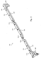
Fig. 2 is a perspective view showing a shank stopper incorporated in the keyboard musical instrument; -
Fig. 3 is a perspective view showing one end portion of the shank stopper; -
Fig. 4 is a perspective view showing the other end portion of the shank stopper; -
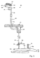
Fig. 5 is a side view showing a change-over mechanism connected to the shank stopper; -
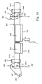
Fig. 6 is a plane view showing the shank stopper in the free position; -
Fig. 7 is a side view showing relative relation between a damper head, a hammer assembly and the shank stopper in the free position; -
Fig. 8 is a plane view showing the shank stopper in the blocking position; -
Fig. 9 is a side view showing relative relation between the damper head, the hammer assembly and the shank stopper in the blocking position; andFig. 10 is a plane view illustrating why the shank stopper is unintentionally changed to the free position. - Referring to
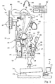
figure 1 of the drawings, a keyboard musical instrument embodying the present invention largely comprises anacoustic piano 100, an electronicsound generating system 200 and asilent system 300. Theacoustic piano 100 is a standard upright piano, and includes akeyboard 110,key action mechanisms 120,hammer assemblies 130, sets ofstrings 140,damper mechanisms 150 and pedal mechanisms (not shown). Thekeyboard 110 are linked with thekey action mechanisms 120 and thedamper mechanisms 150. Thekeyboard 110 selectively actuates thekey action mechanisms 120. Thehammer assemblies 130 are respectively driven for rotation by the associatedkey action mechanisms 120, and strike the associated sets ofstrings 140. Thedamper mechanisms 150 leave the associated sets ofstrings 140, and allow the strings to vibrate for generating acoustic sounds. Thereafter, thedamper mechanisms 150 are brought into contact with the associated sets of strings, and damp the vibrations. Theacoustic piano 100 is hereinlater described in detail. - The electronic
sound generating system 200 includeskey sensors 210, acontroller 220 and aheadphone 230. Thekey sensors 210 are provided under thekeyboard 110, and supply key position signals representative of current key positions to thecontroller 220. Adata processor 221, amemory 222 and atone generator 223 are incorporated in thecontroller 220. Computer programs are stored in thememory 222, and run on thedata processor 221. Thememory 222 further offers a data storage to thedata processor 221. Thedata processor 221 periodically checks the key position signals for current key status, and produces music data codes representative of the key motions. The music data codes are supplied to thetone generator 223, and thetone generator 223 forms an audio signal from the music data codes. The audio signal is supplied to theheadphone 230, and electronic sounds are produced in theheadphone 230. - The
silent system 300 includes ashank stopper 310 and a change-over mechanism 350 (seefigure 5 ). A player manipulates the change-overmechanism 350 so as to change theshank stopper 310 between a free position and a blocking position. While theshank stopper 310 is staying in the free position, thehammer assemblies 130 are allowed to strike the associated sets ofstrings 140 without any interference. However, when theshank stopper 310 is changed to the blocking position, theshank stopper 310 is positioned on the trajectories of thehammer assemblies 130. In this situation, thehammer assemblies 130 rebound on theshank stopper 310 before striking thestrings 140, and the acoustic sound is not generated. - The
acoustic piano 100 is hereinbelow detailed. Eighty-eightkeys 111 are laid on the pattern of a well-known piano keyboard.Capstan buttons 112 project from the rear end portions of thekeys 111, respectively. Though not shown infigure 1 , balance pins offer centers of rotation around a balance rail to thekeys 111. While any force is not exerted on the front ends of thekeys 111, the keys are staying in respective rest positions. When the force is exerted, the key 111 is moved toward an end position. - The
key action mechanisms 120 are similar in structure to one another, and one of thekey action mechanisms 120 is described hereinbelow. Thekey action mechanism 120 includes awhippen 121, ajack 122, awhippen flange 123, ajack flange 124, aregulating button 125, aback check assembly 126 and abridle wire 127. Acenter rail 171 laterally extend over the rear end portions of thekeys 111, and is supported by action brackets (not shown) on akey bed 172. Thewhippen 121 is rotatably connected through thewhippen flange 123 to the rear surface of thecenter rail 171. Thejack flange 124, theback check assembly 126 and thebridle wire 127 project from the upper surface of thewhippen 121. Thejack 122 is rotatably supported by thejack flange 124, and ajack spring 128 urges the jack in the counter clockwise direction. Theregulating button 125 is also supported by thecenter rail 171, and is opposed to thetoe 122a of thejack 122. The distance between theregulating button 125 and thetoe 122a is regulable. Thewhippen 121, thewhippen flange 123, thejack flange 124, thejack 122, thejack spring 128, theback check assembly 126 and thebridle wire 127 as a whole constitute awhippen assembly 129. While the rear end portion of the associatedkey 111 is resting on aback rail cloth 170, the self weight keeps thewhippen assembly 129 at a home position. - While a player is depressing the associated
key 111, thecapstan button 112 pushes thewhippen assembly 121, and gives rise to a rotation of thewhippen assembly 121 around thewhippen flange 123 in the counter clockwise direction. Thejack 122 also turns round thewhippen flange 123, and gives rise to a rotation of thehammer assembly 130 in the counter clockwise direction. However, thejack 122 does not turn around thejack flange 124. When thetoe 122a is brought into contact with theregulating button 125, thejack 122 quickly turns around thejack flange 124, and escapes from thehammer assembly 130. Then, the hammer assembly starts the free rotation toward the associated set ofstrings 140. - The
hammer assembly 130 includes abutt flange 131, abutt 132, ahammer shank 133 and acatcher 134. Thebutt flange 131 is attached to the front surface of thecenter rail 171, and thebutt 132 is rotatably connected to thebutt flange 131. Thehammer shank 133 upwardly projects from thebutt 132, and thecatcher 134 forwardly projects from thebutt 132. Thecatcher 134 is opposed to theback check assembly 126. - The
hammer assembly 130 further includes abutt spring 135, ahammer 136, a butt underfelt 137, a butt underskin 138 and abridle tape 139. Thebutt spring 135 is inserted between thebutt flange 131 and thebutt 132, and urges thebutt 132 in the clockwise direction. The butt underfelt 137 and the butt underskin 138 are laminated on a lower surface of the but 132, and the butt underskin 138 is contacted with the top surface of thejack 122. Thehammer 136 is attached to thehammer shank 133, and is opposed to the associated set ofstrings 140. Thebridle tape 139 is connected at one end thereof thecatcher 134 and the other end thereof to thebridge wire 127. While thewhippen assembly 129 is returning to the home position, thebridge tape 139 forces thehammer assembly 130 to follow thewhippen assembly 129, and prevents the set ofstrings 140 from undesirable double strike. - A
hammer rail 175 laterally extends over thekey action mechanisms 120, and ahammer rail cloth 176 is adhered to the rear surface of thehammer rail 175. While the rear end portion of the associatedkey 111 is resting on aback rail cloth 170, thebutt spring 135 presses thehammer shank 133 against thehammer rail cloth 176, and the butt underskin 138 is in contact with the top surface of thejack 122. Thehammer 136 is spaced from the associated set ofstrings 140, and thecatcher 134 is also spaced from theback check assembly 126. Thus, thehammer assembly 130 is resting at the home position thereof. - When the
tow 122a is brought into contact with theregulating button 125, thejack 122 quickly turns around thejack flange 124, and escapes from the butt underskin 138. Since thejack 122 gives friction to the butt underskin 130 during the escape, thehammer assembly 130 starts the free rotation around thebutt flange 131 against the elastic force of thebutt string 135. If theshank stopper 310 is out of the trajectory of thehammer shank 133, the hammer strikes the set ofstrings 140, and rebounds. The player releases thedepressed key 111, and the key 111 returns toward the rest position. Thecapstan button 112 is downwardly moved, and the self-weight causes thewhippen assembly 129 to turn around thewhippen flange 123 in the clockwise direction. The jack spring urges thejack 122 in the counter clockwise direction, and the jack returns to its home position. Thebridge tape 139 forces thehammer assembly 130 to follow thewhippen assembly 130, and the butt underskin 130 lands on the top surface of thejack 122. Thehammer shank 133 reaches thehammer rail cloth 176, and thehammer assembly 130 returns to the home position. - The
damper mechanisms 150 are also similar in structure to one another, and only one of thedamper mechanism 150 is described hereinbelow. Thedamper mechanism 150 includes adamper spoon 151, adamper flange 152, adamper lever 153, adamper wire 155, adamper wood 156, damper felts 157 and adamper spring 158. Thedamper spoon 151 projects from the upper surface of the rear end portion of thewhippen 121, and thedamper flange 152 is attached to the upper surface of thecenter rail 171. Thedamper lever 153 is rotatably connected to thedamper flange 152. Thedamper wire 155 projects from thedamper lever 153, and thedamper wood 156 is fixed to the leading end of thedamper wire 155. The damper felts are adhered to the rear surface of thedamper wood 156. Thedamper spring 158 is inserted between thedamper flange 152 and thedamper lever 153, and urges thedamper lever 153 in the counter clockwise direction. As a result, the lower portion of thedamper lever 153 is held in contact with thedamper spoon 151, and the damper felts 157 are pressed against the set ofstrings 140. - While the rear end portion of the associated
key 111 is resting on theback rail cloth 170, thedamper spring 158 presses the damper felts 156 against the set ofstrings 140. The set ofstrings 140 is not allowed to vibrate. While the player is depressing the key 111, thecapstan button 112 rotates thewhippen 121 in the counter clockwise direction as described hereinbefore. The rotation of thewhippen 121 gives rise to inclination of thedamper spoon 151. Thedamper spoon 151 pushes the lower portion of thedamper lever 153 in the clockwise direction against the elastic force of thedamper spring 158, and, accordingly, the rotation of the damper lever 153 spaces the damper felts 157 from the set ofstrings 140. Thus, the set ofstrings 140 is allowed to vibrate. When thehammer 136 strikes the set ofstrings 140, thestrings 140 vibrate, and generate an acoustic sound. - When the player releases the
depressed key 111, thewhippen assembly 129 starts to turn around thewhippen flange 123 in the clockwise direction. This results in that thedamper spoon 151 rises again. Thedamper spring 158 urges thedamper lever 158 to turn in the counter clockwise direction, and the damper felts 157 are brought into contact with the set ofstrings 140. The damper felts 157 damp the vibrations. - Subsequently, description is made on the
silent system 300 with reference tofigures 2 ,3 ,4 and5 . Thesilent system 300 is broken down into theshank stopper 310 and the change-overmechanism 350. Theshank stopper 310 includes arail base 311, thestopper rail segments 312/ 313/ 314 andabsorbers 315/ 316/ 317. The length of therail base 311 is greater than the width of the array of thehammer assemblies 130. Therail base 311 has asloop 311a between ashort portion 311b and along portion 311c. - The
stopper rail segments 312/ 313/ 314 have an L-letter cross section, and boltholes 318 are formed in the upper portions of thestopper rail segments 312/ 313/ 314. The bolt holes 318 are elongated, and are open to the rear surfaces of thestopper rail segments 312/ 313/ 314 as will be better seen infigures 3 and 4 .Bolts 319 respectively pass the bolt holes 318, and are screwed into the short/long end portions 311b/ 311c. Thus, thestopper rail segment 312 is bolted to the upper surface of theshort portion 311b, and the otherstopper rail segments 313/ 314 are bolted to the upper surface of thelong portion 311c. Thestopper rail segment 313 is spaced from thestopper rail segment 314. - The elongated bolt holes 318 make the
stopper rail segments 312/ 313/ 314 projectable and retractable with respect to therail base 311. Even if any one of theabsorbers 315/ 316/ 317 is not appropriately positioned at the blocking position, the manufacturer independently regulates theabsorber 315/ 316/ 317 without an influence on the positions of the other absorbers. Thus, theabsorbers 315/ 316/ 317 respectively enter the optimum blocking positions. This feature is desirable, because the manufacturer prepares all theabsorbers 315/ 316/ 317 in a predetermined thickness for the fabrication and the maintenance in future. This results in reduction in cost. The 315/ 316/ 317 are to be positioned between the escaping points and the striking points, and the gap between the escaping points and the striking points is neither wide nor constant. If thestopper rail segments 312/ 313/ 314 are fixed to therail base 311, the manufacturer feels the positioning work difficult, and widens the gap by changing the regulatingbuttons 125 from the optimum positions. However, the change from the optimum positions damages the key- touch. In this instance, thestopper rail segments 312/ 313/ 314 are independently projectable and retractable. The manufacturer positions theabsorbers 315/ 316/ 317 at the optimum positions without changing the regulatingbuttons 125, and the key touch is never damaged. Thus, it is possible to minimize the variation of the gap between thehammer 136 and thestrings 140 when the key 111 is depressed at an extremely low speed. - The
absorbers 315/ 316/ 317 are attached to the front surfaces of thestopper rail segments 312/ 313/ 314, respectively, and a lamination of felt sheet and an artificial leather sheet is, by way of example, used as each of theabsorbers 315/ 316/ 317. A sheet of urethane foam is available for theabsorber 315/ 316/ 317. - The
absorbers hammer assemblies 130 for a lower-pitched part, thehammer assemblies 130 for a middle-pitched part and thehammer assemblies 130 for a higher-pitched part, respectively. The sets ofstrings 140 are arranged in such a manner that thestrings 140 for the lower-pitched part cross thestrings 140 for the middle-pitched part and thestrings 140 for the higher-pitched part. Accordingly, the hammer heads 136 strike the associated sets ofstrings 140 at the points different in height. Moreover,several hammers 136 and the associateddampers 156/ 157 for the middle-pitched part closer to the lower-pitched part are higher than theother hammers 136 and the associateddampers 156/ 157 for the middle-pitched part. In order to regulate theabsorbers 316/ 316/ 317 to appropriate height, therail base 311 includes thesloop 311a, and thelong portion 311c is partially bent around 311d for the several hammers 136. Thus, thebase rail 311 moves theabsorbers 315/ 316/ 317 to the optimum positions in the blocking position, and theshank stopper 310 does not disturb thehammers 136 and thedampers 156/ 157. - Though not shown in the drawings, the
shank stopper 310 is supported by the action brackets.Figures 3 and 4 show connectors 320/ 340 provided between the action brackets and thebase rail 311. Theconnector 320 includes abracket 321, and thebracket 321 is fixed to the action bracket. Thebracket 321 is broken down into abase portion 322, an L-letter shapedguide portion 323, another L-letter shaped connectingportion 324 and a U-letter shapedcover portion 325. Thebase portion 322 provided a flat upper surface, and the L-letter shapedguide portion 323 upwardly projects from one of the side lines of thebase portion 322, and theshort portion 311b of therail base 311 is moved over theguide portion 323. Astopper 326 is attached to the rear end of theguide portion 323, and sets a limit on the movement of theshort portion 311b. The other L-letter shaped connectingportion 324 downwardly projects from the front end line of thebase portion 322, and the U-letter shapedcover portion 325 is attached to the L-letter shaped connectingportion 324. - The
connector 320 further includes a lever, pins 328/ 329/ 330 and apulley 331. Thepin 328 is fixed to the flat surface of thebase portion 322, and upwardly projects therefrom. Thepin 328 is rotatably received in a hole formed in thelever 327 so that thelever 327 turns around thepin 328. Thepin 329 is fixed to theshort portion 311b, and downwardly projects therefrom. Thepin 329 is inserted into another hole formed in thelever 327, and thepin 329 is rotatable in the hole. Thepin 329 is spaced from thepin 328. Thepin 330 is fixed to thelever 327, and downwardly projects from thelever 327. Thepin 330 is further spaced from thepin 328. Thepulley 331 is rotatably supported by the U-letter shapedportion 325, and directs awire 351 of the change-overmechanism 350 toward thepin 330. Thewire 351 is fixed to thepin 330. When thewire 351 is pulled, thelever 327 turns around thepin 328, and theother pin 329 takes up the rotation of thelever 327. - The
other connector 340 includes abracket 341, pins 342/ 343 and alever 344. Thebracket 341 is fixed to another action bracket, and astopper 345 upwardly projects from thebracket 341. Thepin 342 is fixed to thelong portion 311c, and downwardly projects therefrom. On the other hand, thepin 343 is fixed to thebracket 341, and upwardly projects therefrom. Holes are formed in thelever 344, and thepins 342/ 343 are inserted into the holes, respectively. The relative position between thepins pins pins 328/ 329, therail base 311 and thepins 342/ 343 form a parallel link mechanism, and theabsorbers 315/ 316/ 317 are moved substantially in the fore-and-aft direction of theacoustic piano 100. While therail base 311 is being held in contact with thestoppers 326/ 345, theshank stopper 310 is resting in the free position. On the other hand, when thewire 351 is pulled,convex portions 327a/ 344a are brought into contact with avertical walls 323a/ 341a of theguide portions 323/ 341, and theshank stopper 310 enters the blocking position. -
Figure 5 illustrates the change-overmechanism 350. The change-overmechanism 350 includes asilent pedal 352 turnable around apin 353, a hock projecting from thesilent pedal 352, aconnector 355 connected between thehock 354 and thewire 351, a guide tube 356 and abracket 357. Aslot 180a is formed in thebottom sill 180 of the piano housing, and thesilent pedal 352 project from the inside of the piano housing through theslot 180a. Theconnector 355 has a connectingblock 355a and aring 355b, and thewire 351 is fixed to the connectingblock 355a. Thering 355b is also fixed to the connectingblock 355a, and thehock 354 is engaged with thering 355b. Thewire 351 passes through the guide tube 356, and is moved along the guide tube 356. Ahole 172a is formed in thekey bed 172, and the guide tube 356 passes through thehole 172a. Thebracket 357 is attached to the lower surface of thekey bed 172, and the lower end of the guide tube 356 is fixed to thebracket 357. The guide tube 356 upwardly projects from thekey bed 172, and the upper end of the guide tube 356 reaches under thepulley 331. Though not shown infigure 5 , a ratchet mechanism is provided for thesilent pedal 352, and a spring is provided between thebracket 321 and thelever 327 so as to urge the lever in the clockwise direction infigure 3 . - When the player steps on the
silent pedal 352, thepedal 352 downwardly pulls thewire 351, and the ratchet mechanism keeps thesilent pedal 352 depressed. Thewire 351 changes theshank stopper 310 to the blocking position as described hereinbefore. If the player steps on thesilent pedal 352, again, the ratchet mechanism releases thesilent pedal 352, and the spring urges thelever 327 to turn in the clockwise direction. As a result, thewire 351 upwardly pulls thesilent pedal 352, and thesilent pedal 352 returns to the initial position. - The keyboard musical instrument behaves as follows. Assuming now that a player wishes to play a tune on the
acoustic piano 100. Thesilent pedal 352 is resting in the initial position, and therail base 311 are held in contact with thestoppers figure 6 . Theabsorbers 315/ 316/ 317 are retracted, and theshank stopper 310 is staying in the free position. Theshank stopper 310 is out of the trajectories of thehammer shanks 133, and, accordingly, allows thehammers 136 to strike the associated sets ofstrings 140 as shown infigure 7 . - While the player is playing the tune on the
acoustic piano 100, he is assumed to depress the key shown infigure 1 . Thecapstan button 112 upwardly pushes thewhippen 121, and thewhippen assembly 129 turns around thewhippen flange 123 in the counter clockwise direction without any relative rotation between the whippen 121 and thejack 122. Thejack 122 pushes thebutt 132, and gives rise to a rotation around thebutt flange 131. Thewhippen 121 inclines thedamper spoon 151, and thedamper spoon 151 pushes the lower portion of thedamper lever 153. The inclination of thedamper spoon 151 gives rise to a rotation of thedamper lever 153 around thedamper flange 152 in the clockwise direction against the elastic force of thedamper spring 158. Thedamper lever 153 spaces thedamper head 156/ 157 from the associated set ofstrings 140. Although theshank stopper 310 is in the free position, thedamper wood 156 is not brought into contact with theshank stopper 310 as will be seen infigure 7 . Thus, the set ofstrings 140 gets ready for vibrations. - The
capstan button 112 further pushes up thewhippen 121, and thewhippen assembly 129 is continued to turn around thewhippen flange 123 in the counter clockwise direction. Thetow 122a is brought into contact with theregulating button 125. Theregulating button 125 restricts thetow 122a, and thejack 122 quickly turns around thejack flange 124 in the clockwise direction against the elastic force of thejack spring 128. Then, thejack 122 slides on the butt underskin 138, and escapes from thebutt 132. - Upon escaping from the
butt 132, thehammer assembly 130 starts a free rotation. Thehammer 136 strikes the set ofstrings 140. The set ofstrings 140 vibrates so as to generate the acoustic sound. Thehammer assembly 130 rebounds on the set ofstrings 140, and thecatcher 134 is brought into contact with theback check assembly 126. Thebridle tape 139 does not allow thehammer 136 to strike thestrings 140, again. - The player releases the key 111, and the key 111 returns toward the rest position. The self- weight of the
whippen assembly 129 gives rise to a rotation around thewhippen flange 123 in the clockwise direction. Thedamper spring 158 urges thedamper lever 153 in the counter clockwise direction, and the damper felts 157 are brought into contact with the set ofstrings 140. The damper felts 157 take up the vibrations of thestrings 140. Thetow 122a is left from theregulating button 125, and thejack spring 128 causes thejack 122 to be held in contact with the butt underskin 138, again. - The player is assumed to request the keyboard musical instrument to generate electronic sounds instead of the acoustic sounds. The player steps on the silent pedal 352 (see
figure 5 ), and thewire 351 is pulled down. Thelevers 327/ 344 turn around thepins 328/ 343 in the clockwise direction, and theconvex portions 327a/ 344a are brought into contact with thevertical walls 323a/ 341a, respectively, (seefigure 8 ). Therail base 311, thestopper rail segments 312/ 313/ 314 and theabsorbers 315/ 316/ 317 turn around thepins 328/ 343 together with thelevers 327/ 344. Therail base 311, thestopper rail segments 312/313/ 314 and theabsorbers 315/ 316/ 317 are moved on a virtual plane substantially parallel to thekey bed 172, and theabsorbers 315/ 316/ 317 project toward thehammer shanks 133. Thus, theshank stopper 310 enters into the blocking position. Theabsorbers 315/ 316/ 317 are on the trajectories of thehammer shanks 133, and thehammer shanks 133 rebound on theabsorbers 315/ 316/ 317 before striking thestrings 140 as shown infigure 9 . - The player is assumed to depress the key 111. The
damper mechanism 150 similarly behaves. Thekey action mechanism 120 and thehammer assembly 130 similarly behaves until thejack 122 escapes from thebutt 132, and description is omitted for the sake of simplicity. - The
hammer assembly 130 starts the free rotation at the escape. However, thehammer shank 133 rebounds on theshank stopper 310 before thehammer 136 strikes the set ofstrings 140 as drawn by using dots-and- dash line infigure 9 . Thehammer assembly 130 and thekey action mechanism 120 return to the initial positions as similar to those described hereinbefore. - As will be understood from the foregoing description, the
shank stopper 310 horizontally projects into the trajectories of thehammer shanks 133, and is horizontally retracted therefrom. The horizontal motion prevents therail base 311 from the undesirable twist. Although the change-overmechanism 350 is connected to thelever 327 located at one end of therail base 311, therail base 311 is not substantially twisted, and theshank stopper 310 exactly enters into the blocking position. Thus, theshank stopper 310 is simple and reliable. - While the
shank stopper 310 is resting in the free position, thepins 329/ 342 are closer to thehammer shanks 133 and outside of thepins 328/ 343. When theshank stopper 310 is changed from the free position to the blocking position, thepins 329/ 342 are changed to the positions also closer to thehammer shanks 133 but inside of thepins 328/ 343. In this situation, if thehammer shank 133 rebounds on theabsorber 315/ 316/ 317, force F is exerted on thepins 329/342 (seefigure 10 ), and generate moments around thepins 328/ 343 in the counter clockwise direction. When the player wishes to change theshank stopper 310 to the free position, the change-overmechanism 350 gives rise to moments in the clockwise direction. Thus, the moments due to the force F are opposite to the moments to be required for changing it to the free position. The lateral component forces of the moments are exerted on thevertical walls 323a/ 341a, and thepins 328/ 343 receive the component forces of the moments in the fore-and-aft direction. Thevertical walls 323a/ 341a do not allow thelevers 327/ 344 to further turn in the counter clockwise direction. Thus, theshank stopper 310 is never unintentionally changed to the free position due to the impact against theabsorbers 315/ 316/ 317. The vibrations due to the impact are propagated to theconnectors 320/ 340, and the vibrations are never left in thelevers 327/ 344. - In the above-described embodiment, the
pins 328/ 329 and 342/ 343 and thelevers 327/ 344 as a whole constitute two members - Although the particular embodiment of the present invention has been shown and described, it will be apparent to those skilled in the art that various changes and modifications may be made without departing from the spirit and scope of the present invention.
- The acoustic piano may be a grand piano. The
silent system 300 may be incorporated in another kind of keyboard musical instrument such as, for example, automatic player piano. - The
rail base 311 is never limited to the configuration shown infigure 2 in so far as the rail base does not interfere thedamper mechanisms 150, thestrings 140 and thekey action mechanisms 120. A shank stopper may have more than or less than three stopper rail segments. Cushions may be attached to thestoppers 326/ 345. - The change-over mechanism may be manipulated by a hand. Otherwise, an actuator such as, for example, an electric motor may be connected to the
pin 329 fixed to thelever 327.
Claims (10)
- A keyboard musical instrument having a lateral direction, a fore-and-aft direction perpendicular to said lateral direction, and a vertical direction perpendicular to a virtual plane defined by said lateral direction and said fore-and-aft direction, said keyboard musical instrument comprising:a keyboard (110) having plural keys (111) arranged in said lateral direction, each key being associated to one of the notes forming a scale;plural music strings (140) for generating acoustic tones of said notes, respectively;plural hammers (130) respectively linked with said plural keys for striking said plural music strings, respectively; anda silent system (300) including
a hammer stopper (310) selectively entering a free position where said plural hammers are allowed to strike the associated music strings and a blocking position where said hammers rebound thereon before striking said associated music strings
a change-over means (350) connected to said hammer stopper so as to change said hammer stopper between said free position and said blocking position,
said hammer stopper (310) including two members (327/ 328/ 329, 342/ 343/ 344) spaced apart from one another in said lateral direction and having first end portions and second end portions spaced from said first end portions,
absorbing means (315/ 316/ 317) arranged in such a way that said plural hammers (130) can rebound thereon, and
a movable member (311/ 312/ 313/ 314) supporting said absorbing means (315/ 316/ 317) and connected to said second end portions of said two members (327/ 328/ 329, 342/ 343/ 344),characterized in thatsaid two members (327/ 328/ 329, 342/ 343/ 344) have respective vertical axes of rotation at said first end portions thereof so that said change-over means (350) gives rise to a parallel motion of said absorbing means (315/ 316/ 317) in said fore-and-aft direction on said virtual plane through a rotation of said movable member (327/ 328/ 329, 342/ 343/ 344) around said axes of rotation. - The keyboard musical instrument as set forth in claim 1, in which each of said two members includes a first pin (328, 343) connected to a stationary member (321, 341) and having one of said vertical axes, a second pin (329, 342) connected to said movable member and a lever (327, 344) connected at the first end portion to said first pin and at the second end portion to said second pin.
- The keyboard musical instrument as set forth in claim 2, in which said
second pin (329, 342) of each of said two members is arranged to be positioned on one side with respect to the associated first pin (328, 343) while said hammer stopper is resting in said free position, the second pins of said two members are arranged to be changed to the other sides with respect to the first pins when said hammer stopper is changed to said blocking positions through a first rotation of said two members, and a force exerted on said hammer stopper at the rebound gives rise to said first rotation. - The keyboard musical instrument as set forth in claim 3, in which said two members are respectively arranged to be brought into contact with first stoppers (323a, 341a) when said hammer stopper enters said blocking position.
- The keyboard musical instrument as set forth in claim 3, in which said two members are respectively arranged to be brought into contact with first stoppers (326, 345) when said hammer stopper enters said free position.
- The keyboard musical instrument as set forth in claim 3, in which said two members are respectively arranged to be brought into contact with first stoppers (323a, 341a) when said hammer stopper enters said blocking position, and said two members are respectively arranged to be rought into contact with second stoppers (326, 345) when said hammer stopper enters said blocking position.
- The keyboard musical instrument as set forth in claim 1, in which said absorbing means has plural absorbers (315/ 316/ 317) attached to said movable member at intervals, and said movable member includes a rail base (311) and stopper rail brackets (312/ 313/ 314) connected between said rail base and said absorbers.
- The keyboard musical instrument as set forth in claim 7, in which said stopper rail brackets (312, 313, 314) are independently projectable and retractable with respect to said rail base (311).
- The keyboard musical instrument as set forth in claim 1, further comprising plural key action mechanisms (120) respectively provided between said plural keys and said plural hammers and giving rise to rotations of said plural hammers when a player selectively depresses said plural keys.
- The keyboard musical instrument as set forth in claim 9, further comprising an electronic sound generating system (200) monitoring said keyboard to see what key is depressed by said player for selectively generating electronic sounds.
Applications Claiming Priority (2)
| Application Number | Priority Date | Filing Date | Title |
|---|---|---|---|
| JP1449099 | 1999-01-22 | ||
| JP01449099A JP3292164B2 (en) | 1999-01-22 | 1999-01-22 | Keyboard instrument silencer |
Publications (3)
| Publication Number | Publication Date |
|---|---|
| EP1022718A2 EP1022718A2 (en) | 2000-07-26 |
| EP1022718A3 EP1022718A3 (en) | 2009-12-02 |
| EP1022718B1 true EP1022718B1 (en) | 2011-10-19 |
Family
ID=11862506
Family Applications (1)
| Application Number | Title | Priority Date | Filing Date |
|---|---|---|---|
| EP00101016A Expired - Lifetime EP1022718B1 (en) | 1999-01-22 | 2000-01-19 | Keyboard musical instrument having hammer stopper changed between free position and blocking position through turn on horizontal plane |
Country Status (3)
| Country | Link |
|---|---|
| US (1) | US6265647B1 (en) |
| EP (1) | EP1022718B1 (en) |
| JP (1) | JP3292164B2 (en) |
Families Citing this family (8)
| Publication number | Priority date | Publication date | Assignee | Title |
|---|---|---|---|---|
| JP4232325B2 (en) * | 2000-06-21 | 2009-03-04 | ヤマハ株式会社 | Locking device |
| JP3743363B2 (en) * | 2001-12-13 | 2006-02-08 | ヤマハ株式会社 | Silencer for keyboard instruments |
| US7825312B2 (en) | 2008-02-27 | 2010-11-02 | Steinway Musical Instruments, Inc. | Pianos playable in acoustic and silent modes |
| US8541673B2 (en) | 2009-04-24 | 2013-09-24 | Steinway Musical Instruments, Inc. | Hammer stoppers for pianos having acoustic and silent modes |
| US8148620B2 (en) | 2009-04-24 | 2012-04-03 | Steinway Musical Instruments, Inc. | Hammer stoppers and use thereof in pianos playable in acoustic and silent modes |
| WO2018090798A1 (en) | 2016-11-17 | 2018-05-24 | Sunland Information Technology Co., Ltd. | System and method for recording user performance of keyboard instrument |
| WO2018129729A1 (en) * | 2017-01-16 | 2018-07-19 | Sunland Information Technology Co., Ltd. | Piano system and method thereof |
| SI25534A (en) * | 2017-10-24 | 2019-04-30 | Antun Merkoci | Aliquote sounds damping device and method |
Family Cites Families (7)
| Publication number | Priority date | Publication date | Assignee | Title |
|---|---|---|---|---|
| US5374775A (en) * | 1992-06-09 | 1994-12-20 | Yamaha Corporation | Keyboard instrument for selectively producing mechanical sounds and synthetic sounds without any mechanical vibrations on music wires |
| JP3463365B2 (en) | 1993-11-30 | 2003-11-05 | ヤマハ株式会社 | Keyboard instrument |
| JP2901864B2 (en) | 1994-02-18 | 1999-06-07 | 株式会社河合楽器製作所 | Grand piano silencer |
| JP2969039B2 (en) | 1994-03-22 | 1999-11-02 | 株式会社河合楽器製作所 | Piano silencer |
| JPH07334150A (en) * | 1994-06-13 | 1995-12-22 | Yamaha Corp | Keyboard instrument |
| JP2743862B2 (en) * | 1994-08-30 | 1998-04-22 | ヤマハ株式会社 | Keyboard instrument |
| JPH10149154A (en) | 1996-09-18 | 1998-06-02 | Yamaha Corp | Slencer device for keyboard musical instrument |
-
1999
- 1999-01-22 JP JP01449099A patent/JP3292164B2/en not_active Expired - Lifetime
-
2000
- 2000-01-19 EP EP00101016A patent/EP1022718B1/en not_active Expired - Lifetime
- 2000-01-21 US US09/489,301 patent/US6265647B1/en not_active Expired - Lifetime
Also Published As
| Publication number | Publication date |
|---|---|
| US6265647B1 (en) | 2001-07-24 |
| JP3292164B2 (en) | 2002-06-17 |
| EP1022718A2 (en) | 2000-07-26 |
| EP1022718A3 (en) | 2009-12-02 |
| JP2000214842A (en) | 2000-08-04 |
Similar Documents
| Publication | Publication Date | Title |
|---|---|---|
| US5949013A (en) | Keyboard musical instrument equipped with hammer stopper implemented by parallelogram link mechanism | |
| EP0700029B1 (en) | Keyboard musical instrument equipped with hammer shank stopper where hammer assembly rebounds without deflection of shank | |
| EP0655728B1 (en) | Electronic keyboard instrument having hammer stopper outwardly extending from hammer shank and method of remodeling piano into the electronic keyboard instrument | |
| US5565636A (en) | Keyboard musical instrument equipped with driving unit for hammer stopper located in wide space in front of hammer assemblies | |
| US5610356A (en) | Keyboard musical instrument having hammer stopper exactly position at blocking position | |
| EP0655727B1 (en) | Keyboard musical instrument with movable key bed for performing music without acoustic sounds | |
| EP0689182B1 (en) | Keyboard musical instrument having jacks changeable in escape speed between acoustic sound mode and silent mode | |
| EP1022718B1 (en) | Keyboard musical instrument having hammer stopper changed between free position and blocking position through turn on horizontal plane | |
| US6194649B1 (en) | Keyboard musical instrument equipped with partially repaireable change-over mechanism for changing hammer stopper | |
| KR100418153B1 (en) | Pedal mechanisms assembled into unit and keyboard musical instrument equipped with the same | |
| US5528969A (en) | Damper unit for a piano | |
| US6452079B2 (en) | Keyboard musical instrument equipped with hammer stopper promptly driven for rotation by means of rigid link work | |
| EP1424682B1 (en) | Keyboard instrument having pedal mechanism | |
| US6011214A (en) | Keyboard instruments having hammer stopper outwardly extending from hammer shank and method of remodeling piano into the keyboard instrument | |
| KR20040075739A (en) | Keyboard Musical Instrument Equipped With Automatic Top Board Spacer | |
| US5844154A (en) | Combination acoustic and electronic piano in which the acoustic action is disabled when played in the electronic mode | |
| US5874687A (en) | Keyboard instrument having hammer stopper outwardly extending from hammer shank and method of remodeling piano into the keyboard instrument | |
| US5524519A (en) | Piano provided with a mechanism for controlling string striking movement | |
| JP3456216B2 (en) | Keyboard instrument | |
| JPH0887269A (en) | Keyboard musical instrument | |
| JP3714349B2 (en) | Silencer for keyboard instrument and keyboard instrument | |
| JP3438741B2 (en) | Keyboard instrument | |
| JPH11282471A (en) | Keyboard instrument | |
| JP3456733B2 (en) | piano | |
| JP3420005B2 (en) | Keyboard device |
Legal Events
| Date | Code | Title | Description |
|---|---|---|---|
| PUAI | Public reference made under article 153(3) epc to a published international application that has entered the european phase |
Free format text: ORIGINAL CODE: 0009012 |
|
| AK | Designated contracting states |
Kind code of ref document: A2 Designated state(s): AT BE CH CY DE DK ES FI FR GB GR IE IT LI LU MC NL PT SE |
|
| AX | Request for extension of the european patent |
Free format text: AL;LT;LV;MK;RO;SI |
|
| RAP1 | Party data changed (applicant data changed or rights of an application transferred) |
Owner name: YAMAHA CORPORATION |
|
| PUAL | Search report despatched |
Free format text: ORIGINAL CODE: 0009013 |
|
| AK | Designated contracting states |
Kind code of ref document: A3 Designated state(s): AT BE CH CY DE DK ES FI FR GB GR IE IT LI LU MC NL PT SE |
|
| AX | Request for extension of the european patent |
Extension state: AL LT LV MK RO SI |
|
| 17P | Request for examination filed |
Effective date: 20100121 |
|
| 17Q | First examination report despatched |
Effective date: 20100219 |
|
| AKX | Designation fees paid |
Designated state(s): DE GB |
|
| GRAP | Despatch of communication of intention to grant a patent |
Free format text: ORIGINAL CODE: EPIDOSNIGR1 |
|
| GRAS | Grant fee paid |
Free format text: ORIGINAL CODE: EPIDOSNIGR3 |
|
| GRAA | (expected) grant |
Free format text: ORIGINAL CODE: 0009210 |
|
| AK | Designated contracting states |
Kind code of ref document: B1 Designated state(s): DE GB |
|
| REG | Reference to a national code |
Ref country code: GB Ref legal event code: FG4D |
|
| REG | Reference to a national code |
Ref country code: DE Ref legal event code: R096 Ref document number: 60046563 Country of ref document: DE Effective date: 20111208 |
|
| PLBE | No opposition filed within time limit |
Free format text: ORIGINAL CODE: 0009261 |
|
| STAA | Information on the status of an ep patent application or granted ep patent |
Free format text: STATUS: NO OPPOSITION FILED WITHIN TIME LIMIT |
|
| 26N | No opposition filed |
Effective date: 20120720 |
|
| REG | Reference to a national code |
Ref country code: DE Ref legal event code: R097 Ref document number: 60046563 Country of ref document: DE Effective date: 20120720 |
|
| PGFP | Annual fee paid to national office [announced via postgrant information from national office to epo] |
Ref country code: GB Payment date: 20170118 Year of fee payment: 18 |
|
| GBPC | Gb: european patent ceased through non-payment of renewal fee |
Effective date: 20180119 |
|
| PG25 | Lapsed in a contracting state [announced via postgrant information from national office to epo] |
Ref country code: GB Free format text: LAPSE BECAUSE OF NON-PAYMENT OF DUE FEES Effective date: 20180119 |
|
| PGFP | Annual fee paid to national office [announced via postgrant information from national office to epo] |
Ref country code: DE Payment date: 20190123 Year of fee payment: 20 |
|
| REG | Reference to a national code |
Ref country code: DE Ref legal event code: R071 Ref document number: 60046563 Country of ref document: DE |