EP1022568B1 - Anordnung zur Drehzahlmessung - Google Patents
Anordnung zur Drehzahlmessung Download PDFInfo
- Publication number
- EP1022568B1 EP1022568B1 EP00200124A EP00200124A EP1022568B1 EP 1022568 B1 EP1022568 B1 EP 1022568B1 EP 00200124 A EP00200124 A EP 00200124A EP 00200124 A EP00200124 A EP 00200124A EP 1022568 B1 EP1022568 B1 EP 1022568B1
- Authority
- EP
- European Patent Office
- Prior art keywords
- sensor
- wheel
- layer
- electrically conducting
- sensor elements
- Prior art date
- Legal status (The legal status is an assumption and is not a legal conclusion. Google has not performed a legal analysis and makes no representation as to the accuracy of the status listed.)
- Expired - Lifetime
Links
- 239000010409 thin film Substances 0.000 claims description 13
- 238000011156 evaluation Methods 0.000 claims description 12
- 230000008878 coupling Effects 0.000 claims description 10
- 238000010168 coupling process Methods 0.000 claims description 10
- 238000005859 coupling reaction Methods 0.000 claims description 10
- 238000005516 engineering process Methods 0.000 claims description 10
- 239000000758 substrate Substances 0.000 claims description 6
- 239000007769 metal material Substances 0.000 claims description 3
- 230000008021 deposition Effects 0.000 claims description 2
- 230000005405 multipole Effects 0.000 claims 2
- 230000005415 magnetization Effects 0.000 claims 1
- 238000000034 method Methods 0.000 claims 1
- 230000005672 electromagnetic field Effects 0.000 description 6
- 238000009413 insulation Methods 0.000 description 3
- 239000003990 capacitor Substances 0.000 description 2
- 238000010586 diagram Methods 0.000 description 2
- 230000005670 electromagnetic radiation Effects 0.000 description 2
- 238000002955 isolation Methods 0.000 description 2
- 238000004519 manufacturing process Methods 0.000 description 2
- 238000005259 measurement Methods 0.000 description 2
- 230000009286 beneficial effect Effects 0.000 description 1
- 230000001419 dependent effect Effects 0.000 description 1
- 230000003292 diminished effect Effects 0.000 description 1
- 238000010292 electrical insulation Methods 0.000 description 1
- 230000005611 electricity Effects 0.000 description 1
- 230000005855 radiation Effects 0.000 description 1
Images

Classifications
-
- G—PHYSICS
- G01—MEASURING; TESTING
- G01D—MEASURING NOT SPECIALLY ADAPTED FOR A SPECIFIC VARIABLE; ARRANGEMENTS FOR MEASURING TWO OR MORE VARIABLES NOT COVERED IN A SINGLE OTHER SUBCLASS; TARIFF METERING APPARATUS; MEASURING OR TESTING NOT OTHERWISE PROVIDED FOR
- G01D5/00—Mechanical means for transferring the output of a sensing member; Means for converting the output of a sensing member to another variable where the form or nature of the sensing member does not constrain the means for converting; Transducers not specially adapted for a specific variable
- G01D5/12—Mechanical means for transferring the output of a sensing member; Means for converting the output of a sensing member to another variable where the form or nature of the sensing member does not constrain the means for converting; Transducers not specially adapted for a specific variable using electric or magnetic means
- G01D5/14—Mechanical means for transferring the output of a sensing member; Means for converting the output of a sensing member to another variable where the form or nature of the sensing member does not constrain the means for converting; Transducers not specially adapted for a specific variable using electric or magnetic means influencing the magnitude of a current or voltage
- G01D5/142—Mechanical means for transferring the output of a sensing member; Means for converting the output of a sensing member to another variable where the form or nature of the sensing member does not constrain the means for converting; Transducers not specially adapted for a specific variable using electric or magnetic means influencing the magnitude of a current or voltage using Hall-effect devices
- G01D5/147—Mechanical means for transferring the output of a sensing member; Means for converting the output of a sensing member to another variable where the form or nature of the sensing member does not constrain the means for converting; Transducers not specially adapted for a specific variable using electric or magnetic means influencing the magnitude of a current or voltage using Hall-effect devices influenced by the movement of a third element, the position of Hall device and the source of magnetic field being fixed in respect to each other
-
- G—PHYSICS
- G01—MEASURING; TESTING
- G01D—MEASURING NOT SPECIALLY ADAPTED FOR A SPECIFIC VARIABLE; ARRANGEMENTS FOR MEASURING TWO OR MORE VARIABLES NOT COVERED IN A SINGLE OTHER SUBCLASS; TARIFF METERING APPARATUS; MEASURING OR TESTING NOT OTHERWISE PROVIDED FOR
- G01D5/00—Mechanical means for transferring the output of a sensing member; Means for converting the output of a sensing member to another variable where the form or nature of the sensing member does not constrain the means for converting; Transducers not specially adapted for a specific variable
- G01D5/12—Mechanical means for transferring the output of a sensing member; Means for converting the output of a sensing member to another variable where the form or nature of the sensing member does not constrain the means for converting; Transducers not specially adapted for a specific variable using electric or magnetic means
- G01D5/14—Mechanical means for transferring the output of a sensing member; Means for converting the output of a sensing member to another variable where the form or nature of the sensing member does not constrain the means for converting; Transducers not specially adapted for a specific variable using electric or magnetic means influencing the magnitude of a current or voltage
- G01D5/142—Mechanical means for transferring the output of a sensing member; Means for converting the output of a sensing member to another variable where the form or nature of the sensing member does not constrain the means for converting; Transducers not specially adapted for a specific variable using electric or magnetic means influencing the magnitude of a current or voltage using Hall-effect devices
- G01D5/145—Mechanical means for transferring the output of a sensing member; Means for converting the output of a sensing member to another variable where the form or nature of the sensing member does not constrain the means for converting; Transducers not specially adapted for a specific variable using electric or magnetic means influencing the magnitude of a current or voltage using Hall-effect devices influenced by the relative movement between the Hall device and magnetic fields
-
- G—PHYSICS
- G01—MEASURING; TESTING
- G01P—MEASURING LINEAR OR ANGULAR SPEED, ACCELERATION, DECELERATION, OR SHOCK; INDICATING PRESENCE, ABSENCE, OR DIRECTION, OF MOVEMENT
- G01P3/00—Measuring linear or angular speed; Measuring differences of linear or angular speeds
- G01P3/42—Devices characterised by the use of electric or magnetic means
- G01P3/44—Devices characterised by the use of electric or magnetic means for measuring angular speed
- G01P3/48—Devices characterised by the use of electric or magnetic means for measuring angular speed by measuring frequency of generated current or voltage
- G01P3/481—Devices characterised by the use of electric or magnetic means for measuring angular speed by measuring frequency of generated current or voltage of pulse signals
- G01P3/483—Devices characterised by the use of electric or magnetic means for measuring angular speed by measuring frequency of generated current or voltage of pulse signals delivered by variable capacitance detectors
-
- G—PHYSICS
- G01—MEASURING; TESTING
- G01P—MEASURING LINEAR OR ANGULAR SPEED, ACCELERATION, DECELERATION, OR SHOCK; INDICATING PRESENCE, ABSENCE, OR DIRECTION, OF MOVEMENT
- G01P3/00—Measuring linear or angular speed; Measuring differences of linear or angular speeds
- G01P3/42—Devices characterised by the use of electric or magnetic means
- G01P3/44—Devices characterised by the use of electric or magnetic means for measuring angular speed
- G01P3/48—Devices characterised by the use of electric or magnetic means for measuring angular speed by measuring frequency of generated current or voltage
- G01P3/481—Devices characterised by the use of electric or magnetic means for measuring angular speed by measuring frequency of generated current or voltage of pulse signals
- G01P3/487—Devices characterised by the use of electric or magnetic means for measuring angular speed by measuring frequency of generated current or voltage of pulse signals delivered by rotating magnets
Definitions
- the invention relates to an arrangement for measuring the rotational speed of a rotatable Rades on or in a vehicle with a produced by thin-film technology Sensor which has magnetoresistive sensor elements and by means of which a Magnetic field is measured, which by means of a structuring of the wheel depends on whose speed is modulated.
- an electrically conductive layer is provided on the sensor on the surface facing the wheel, which reduces a capacitive coupling occurring between the wheel and the sensor elements without the layer and which in turn is capacitively coupled to the wheel.
- the electrically conductive layer which consists of a metallic material, is produced in thin-film technology on at least one side of the sensor by means of layer deposition on an insulating layer and has a layer thickness of approximately 0.2 to 3 ⁇ m, the electrically conductive layer is electrically contacted outside the substrate on which the sensor elements are constructed, that the electrical contacting is provided by means of non-thin-film means and that by means of the electrical contacting a coupling of the electrically conductive layer takes place with a reference potential.
- This electric conductive layer has the task of capacitive coupling between the Sensor elements of the sensor on the one hand and the wheel and its tooth structure on the other hand. It should therefore at provided electrical conductive layer the capacitive coupling between the sensor elements and the wheel relative to the Condition without the layer being diminished. This ensures that even outside the Sensor or the sensor elements irradiated by electromagnetic fields High frequency currents over the between the electrically conductive layer and the wheel formed capacity flow. This is the still existing capacity between the sensor elements and the wheel are reduced so that the over this capacity flowing interference currents are reduced, usually significantly reduced, are. So it's going through the electrically conductive layer for irradiated interference currents formed a new path, the deflects the interference currents from the sensor elements.
- the layer should, in order to make the capacity as well as possible, from a consist of metallic material and be electrically conductive. It is according to the invention Advantageously applied in thin-film technology, so that they are in a same Manufacturing process as the sensor elements can be generated.
- the electrical layer is created on an insulating layer, thus ensuring complete isolation between the is ensured electrically conductive layer and the sensor elements of the sensor.
- the electrically conductive layer has a layer thickness of about 0.2 to 3 ⁇ m, so that it in turn is so thin that on the electrically conductive layer from the outside in turn, electromagnetic fields in this layer do not themselves Form interference currents that are undesirable.
- the electrically conductive layer exclusively outside the substrate on which the sensor elements are produced, electrical contacted.
- the electrically conductive layer via an electrical Contacting coupled to a reference potential, the reference potential of the Sensor corresponds.
- radio frequency interference currents preferably via the between the electrically conductive layer and the wheel Capacity of the vehicle flow. This is a flow of interference currents over the Sensor elements reduced, if not largely switched off, so that the currents, which supply the sensor elements and which serve to measure the speed, much less are loaded with HF interference currents.
- the structure of the electrically conductive layer has succeeded in a simple manner since for producing this layer and the insulating layer provided below also Thin-film means are provided, which are usually also in the production the sensor or its sensor elements are used.
- the improved EMC compatibility is of particular importance to, as the location of the sensor in the wheel arches with respect to electromagnetic Radiation is particularly sensitive and these sensors have leads, which also in particularly Störstrahlintensiven areas of the vehicle are laid.
- the provided outside the substrate of the sensor elements electrical contact
- the electrically conductive layer may be advantageous, as in a further embodiment the invention is provided according to claim 3, carried out by means of bonding. This is also therefore advantageous because the electrical connections of the sensor elements to the sensor usually also be made by means of bonding. Thus, for the bonding of electrically conductive layer in the same operation to make electrical contact, so that there is little additional effort for this.
- the electrically conductive layer covers as in a further embodiment the invention of claim 4 is provided, the wheel-facing side of the sensor from.
- the electrically conductive layer the desired Capacity between her and the wheel form and thus the capacity between the sensor and diminish the wheel.
- the electrical signals that supply the sensor elements are usually in a first stage evaluated by means of an evaluation circuit, directly in the area of the sensor elements is arranged. Therefore, can be advantageous as according to a further embodiment of The invention is provided according to claim 5, the electrically conductive layer and this evaluation circuit at least on one side with cover and so the EMC compatibility on improve by already in the area of the transmitter the path to the capacity too is placed down the wheel.
- the electrically conductive layer does not have to be a completely closed layer can, for example, as according to a further embodiment of the invention according to Claim 6 is provided, also have a comb structure. Also other structures are conceivable as long as the mentioned purpose is fulfilled.
- an arrangement is selected as the sensor, which, as according to another Arrangement according to claim 9 is provided, four magnetoresistive sensor elements which form a bridge.
- Such arrangements allow a particularly good Measurement and have largely, for example, for the purposes of ABS sensors enforced.
- Fig. 1 initially only one sensor 1 of an inventive arrangement is shown. This sensor 1 is partially shown in section.
- the sensor 1 according to FIG. 1 is constructed on a metallic carrier 2, which on the one hand serves as a mechanical carrier and on the other hand coupled to reference potential.
- a sensor layer 3 which is produced in thin-film technology.
- insulation layer 4 On the Sensor layer 3 is provided in Fig. 1 only partially shown insulation layer 4.
- an electrical conductive layer 5 On the insulating layer 4 is also by means of thin-film means an electrical conductive layer 5 is provided.
- an electrical contact 6, Arranged externally on the substrate is an electrical contact 6, which is instantaneous is connected to the metallic carrier 2 and which is coupled to reference potential. There are further provided three further contacts 7, which via bonding connections. 8 are coupled with corresponding terminals of the sensor layer 3. About these connections 7 signals of the sensor elements are added or removed. It is further provided a bonding 9, by means of which the reference potential to which the metallic carrier 2 is coupled is also guided to the sensor elements.
- the electrical conductive layer 5 by means of another bond 10 also with coupled to the metallic carrier 2, so that the electrically conductive layer 5 with Reference potential is coupled.
- the layers 4 and 5 are only in the Section are shown.
- the insulating layer 4 covers, and in particular, the electrically conductive layer 5, the sensor layer 3 at least on one side, in the illustration according to Fig. 1 usefully on the top, as completely as possible.
- This page is also usefully the one, which arranged against a structuring of the wheel is.
- Fig. 1 shows that the insulating layer 4 and the electrically conductive layer 5 also How the sensor layer 3 can be produced by means of thin-film technology. It only two further steps are necessary to produce the two layers; However, the same technology can be used for this, so that the additional Effort is low.
- the complete isolation between the electrically conductive layer 5 and the sensor layer 3 can be tested before creating the bond 10. Only then can be beneficial the bond 10 are generated.
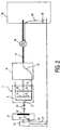
- Fig. 2 the sensor 1 is again. He is here indicated electrotechnically, wherein four sensor elements 11, 12, 13 and 14 are indicated, which form a bridge and the are coupled via terminals 15 with a downstream evaluation circuit 16.
- the electrically conductive layer 5 is indicated.
- the evaluation circuit 16 is via a wire connection 17 another evaluation 18 downstream, which is for example an ABS electronics can act.
- the sensor 1 is arranged opposite a rotatable wheel 21 of a vehicle.
- a wheel 21 of a vehicle there it may be, for example, a wheel that is non-rotatable with a wheel of the vehicle, on which this can move, is coupled.
- a structuring 22 is provided which, for example can in turn be magnetized or magnetized from a multipolar Layer and thus produces a speed-dependent modulated magnetic field, that measured by means of the sensor elements 11, 12, 13, 14 and further by means of the circuits 16 and 18 can be evaluated. From the modulation frequency of this Signals, the speed of the wheel 21 can be determined.
- Such systems become, for example used for ABS sensors.
- the wheel 21, is directly or at least capacitively connected to the vehicle 23 on which it is located is located, electrically coupled.
- Such radiated interference currents are looking for, for example, in that shown in FIG Arrangement in a vehicle, a path over which they can flow.
- This Path can be generated directly by electrical connection, but it can also be through capacitive coupling can be closed.
- connections 31 this path is indicated by connections 31. It arise here partially direct connections, such as between the transmitter 18, the electrical supply line 17, the evaluation circuit 16 and the sensor first
- a direct contact is not given, so that the Electricity over capacity flows. This can, for example, in the area between the transmitter 18 and reference potential via a capacitor 32 to be the case.
- the Space between the sensor 1 and the wheel 21 also has a capacity 33 formed over which the RF interference current can flow.
- the wheel 21 is either directly above a fixture 23 connected to the reference potential of the vehicle, at least forms but there is a capacity 34 over which the RF interference current can flow.
- the electrically conductive Layer 5 is not provided and the capacity 33 would not, as in the figure indicated between this electrically conductive layer 5 and the wheel 21, but between the sensor 1 and its sensor elements 11, 12, 13, 14 on the one hand and the On the other hand, train the wheel. This would cause the interference current directly through the sensor elements 11, 12, 13, 14 or whose supply lines flow and would the evaluation of their Disturb signals.
- the electrically conductive layer 5 is provided, which in turn produces a good capacitive coupling across the capacitor 33 with the wheel 21.
- These Capacitance 33 thus predominantly forms between the electrically conductive layer 5 and the wheel 21.
- the HF interference current flows predominantly over this capacitance 33 between the electrically conductive layer 5 and the wheel 21.
Landscapes
- Physics & Mathematics (AREA)
- General Physics & Mathematics (AREA)
- Transmission And Conversion Of Sensor Element Output (AREA)
- Hall/Mr Elements (AREA)
Description
dass die elektrisch leitfähige Schicht, welche aus einem metallischen Material besteht, in Dünnschichttechnik wenigstens auf einer Seite des Sensors mittels Schichtabscheidung auf einer Isolationsschicht erzeugt ist und etwa eine Schichtdicke von 0,2 bis 3 µm aufweist,
dass die elektrisch leitfähige Schicht außerhalb des Substrats, auf dem die Sensorelemente aufgebaut sind, elektrisch kontaktiert ist,
dass die elektrische Kontaktierung mittels nicht-dünnschichttechnischer Mittel vorgesehen ist
und dass mittels der elektrischen Kontaktierung eine Kopplung der elektrisch leitfähigen Schicht mit einem Bezugspotential erfolgt.
Claims (9)
- Anordnung zur Messung der Drehzahl eines drehbaren Rades (21) an oder in einem Fahrzeug (23) mit einem mittels Dünnschichttechnik erzeugten Sensor (1), welcher magnetoresistive Sensorelemente (11,12,13,14) aufweist und mittels welchem ein Magnetfeld gemessen wird, das mittels einer Strukturierung (22) des Rades (21) abhängig von dessen Drehzahl moduliert wird, dadurch gekennzeichnet, dass an dem Sensor (1) an der dem Rad (21) zugewandten Oberfläche eine elektrisch leitfähige Schicht (5) vorgesehen ist, welche eine ohne die Schicht (5) auftretende kapazitive Kopplung zwischen dem Rad (21) und den Sensorelementen (11,12,13,14) vermindert und welche ihrerseits kapazitiv mit dem Rad (21) gekoppelt ist,
dass die elektrisch leitfähige Schicht (5), welche aus einem metallischen Material besteht, in Dünnschichttechnik wenigstens auf der dem Rad (21) zugewandten Seite des Sensors (1) mittels Schichtabscheidung auf einer Isolationsschicht (4) erzeugt ist und etwa eine Schichtdicke von 0,2 bis 3 µm aufweist,
dass die elektrisch leitfähige Schicht (5) außerhalb des Substrats (3), auf dem die Sensorelemente (11,12,13,14) aufgebaut sind, elektrisch kontaktiert ist,
dass die elektrische Kontaktierung (10) mittels nicht-dünnschichttechnischer Mittel vorgesehen ist
und dass mittels der elektrischen Kontaktierung (10) eine Kopplung der elektrisch leitfähigen Schicht (5) mit einem Bezugspotential erfolgt. - Anordnung nach Anspruch 1, dadurch gekennzeichnet, daß das Rad (21) mit einem Fahrzeugrad, auf dem das Fahrzeug rollbar ist, drehgekoppelt ist und daß der Sensor (1) als Drehzahlsensor für ein Anti-Blockier-System des Fahrzeugs vorgesehen ist.
- Anordnung nach Anspruch 1, dadurch gekennzeichnet, daß die elektrische Kontaktierung (10) der elektrisch leitfähigen Schicht (5) mittels Bonden an dem Sensor (1) erfolgt.
- Anordnung nach Anspruch 1, dadurch gekennzeichnet, dass die elektrisch leitfähige Schicht (5) die Sensorelemente (11,12,13,14) wenigstens auf der dem Rad (21) zugewandten Seite des Sensors (1) vollständig abdeckt.
- Anordnung nach Anspruch 1 oder 4, dadurch gekennzeichnet, daß die Ausgangssignale der Sensorelemente (11,12,13,14) mittels einer Auswerteschaltung (16) ausgewertet werden und daß die elektrisch leitfähige Schicht (5) auch die Auswerteschaltung (16) wenigstens einseitig abdeckt.
- Anordnung nach Anspruch 1, dadurch gekennzeichnet, daß die elektrisch leitfähige Schicht (5) eine Kammstruktur aufweist.
- Anordnung nach Anspruch 1, dadurch gekennzeichnet, daß die Strukturierung (22) des Rades (21) als mehrpolige Magnetisierung oder als mehrpolig magnetisierte Schicht realisiert ist.
- Anordnung nach Anspruch 1, dadurch gekennzeichnet, daß ein Dauermagnet auf der dem Rad (21) abgewandten Seite des Sensors (1) vorgesehen ist.
- Anordnung nach Anspruch 1, dadurch gekennzeichnet, daß der Sensor (1) auf einer Trägerplatte (2) angeordnete und eine Doppel-Brücke bildende magnetoresistive Sensorelemente (11,12,13,14) aufweist.
Applications Claiming Priority (2)
| Application Number | Priority Date | Filing Date | Title |
|---|---|---|---|
| DE19902188 | 1999-01-21 | ||
| DE19902188A DE19902188A1 (de) | 1999-01-21 | 1999-01-21 | Anordnung zur Drehzahlmessung |
Publications (2)
| Publication Number | Publication Date |
|---|---|
| EP1022568A1 EP1022568A1 (de) | 2000-07-26 |
| EP1022568B1 true EP1022568B1 (de) | 2005-03-23 |
Family
ID=7894881
Family Applications (1)
| Application Number | Title | Priority Date | Filing Date |
|---|---|---|---|
| EP00200124A Expired - Lifetime EP1022568B1 (de) | 1999-01-21 | 2000-01-12 | Anordnung zur Drehzahlmessung |
Country Status (4)
| Country | Link |
|---|---|
| US (1) | US6505513B1 (de) |
| EP (1) | EP1022568B1 (de) |
| JP (1) | JP2000235039A (de) |
| DE (2) | DE19902188A1 (de) |
Families Citing this family (5)
| Publication number | Priority date | Publication date | Assignee | Title |
|---|---|---|---|---|
| DE20018538U1 (de) * | 2000-10-27 | 2002-03-07 | Mannesmann Vdo Ag | Sensormodul |
| US7603892B2 (en) * | 2006-06-02 | 2009-10-20 | Honeywell International Inc. | Cam and crank sensor with current limiting open collector output for conducted emissions improvement |
| EP2161974A1 (de) | 2008-09-09 | 2010-03-10 | Hegutechnik v. Gutwald KG | Bifunktionale EMV Beschichtung |
| US9121880B2 (en) * | 2011-11-04 | 2015-09-01 | Infineon Technologies Ag | Magnetic sensor device |
| US9201123B2 (en) | 2011-11-04 | 2015-12-01 | Infineon Technologies Ag | Magnetic sensor device and a method for fabricating the same |
Family Cites Families (11)
| Publication number | Priority date | Publication date | Assignee | Title |
|---|---|---|---|---|
| DE3426785A1 (de) * | 1984-07-20 | 1986-01-23 | Bosch Gmbh Robert | Magnetoresistiver sensor zur messung von magnetfeldaenderungen und verfahren zu seiner herstellung |
| US4802043A (en) * | 1985-03-25 | 1989-01-31 | Hitachi, Ltd. | Magneto-resistive head for protecting against output spike noises |
| US4830449A (en) * | 1987-09-17 | 1989-05-16 | Simmonds Precision Products, Inc. | Polarimetric fiber optic speed sensor |
| JPH0421916A (ja) * | 1990-05-16 | 1992-01-24 | Sony Corp | 磁気抵抗効果型薄膜ヘッド |
| US5798639A (en) * | 1994-03-04 | 1998-08-25 | Cts Corporation | Rotary position sensor with improved bearing tolerance |
| DE4407474C2 (de) * | 1994-03-07 | 2000-07-13 | Asm Automation Sensorik Messte | Drehwinkelsensor |
| US5761009A (en) * | 1995-06-07 | 1998-06-02 | International Business Machines Corporation | Having parastic shield for electrostatic discharge protection |
| JP3079528B2 (ja) * | 1996-02-28 | 2000-08-21 | 日本精機株式会社 | 回転検出装置 |
| DE19622462B4 (de) * | 1996-06-05 | 2004-12-09 | Robert Bosch Gmbh | Verfahren und Vorrichtung zur Fehlererkennung |
| DE19640695A1 (de) * | 1996-10-02 | 1998-04-09 | Bosch Gmbh Robert | Magnetoresistiver Sensor mit temperaturstabilem Nullpunkt |
| JP3423566B2 (ja) * | 1997-02-26 | 2003-07-07 | 三菱電機株式会社 | 磁気センサ |
-
1999
- 1999-01-21 DE DE19902188A patent/DE19902188A1/de not_active Withdrawn
-
2000
- 2000-01-12 EP EP00200124A patent/EP1022568B1/de not_active Expired - Lifetime
- 2000-01-12 DE DE50009823T patent/DE50009823D1/de not_active Expired - Lifetime
- 2000-01-18 JP JP2000009276A patent/JP2000235039A/ja active Pending
- 2000-01-18 US US09/483,918 patent/US6505513B1/en not_active Expired - Lifetime
Also Published As
| Publication number | Publication date |
|---|---|
| EP1022568A1 (de) | 2000-07-26 |
| US6505513B1 (en) | 2003-01-14 |
| JP2000235039A (ja) | 2000-08-29 |
| DE19902188A1 (de) | 2000-07-27 |
| DE50009823D1 (de) | 2005-04-28 |
Similar Documents
| Publication | Publication Date | Title |
|---|---|---|
| DE60037790T2 (de) | Magnetisches messsystem mit irreversibler charakteristik, sowie methode zur erzeugung, reparatur und verwendung eines solchen systems | |
| DE69738435T2 (de) | Magnetischer stromsensor | |
| DE69933440T2 (de) | Digitaler magnetischer signalkoppler | |
| DE102005047414B4 (de) | Magnetoresistives Sensormodul und Verfahren zum Herstellen desselben | |
| DE102006022336B4 (de) | Magnetfeldsensor und Sensoranordenung mit demselben | |
| DE112010000848B4 (de) | Schaltungen und Verfahren zum Erzeugen eines Selbsttests eines Magnetfeldsensors | |
| DE69518146T2 (de) | Magnetoresistive struktur mit einer legierungsschicht | |
| DE10028640A1 (de) | Wheatstonebrücke, beinhaltend Brückenelemente, bestehend aus einem Spin-Valve-System, sowie ein Verfahren zu deren Herstellung | |
| DE112009002077T5 (de) | Verfahren und Vorrichtungen für einen integrierten Schaltkreis mit integrierter Energiespeichervorrichtung | |
| EP2470920A1 (de) | Magnetfeldsensor | |
| DE102005022596A1 (de) | Anordnung zur eigensicheren Raddrehzahlerfassung | |
| DE102016111256B4 (de) | Magnetfeldgenerator, Magnetsensorsystem und Magnetsensor | |
| DE4317512A1 (de) | Vorrichtung zur berührungslosen Nullpunkt-, Positions- und Drehwinkelmessung | |
| EP1259832B1 (de) | Magnetfeldmessanordnung mittels einer brückenschaltung von spin-tunnel-elementen und herstellungsverfahren | |
| DE19843348A1 (de) | Magnetoresistives Sensorelement, insbesondere Winkelsensorelement | |
| WO2008040659A2 (de) | Verfahren zum betreiben eines magnetfeldsensors und zugehöriger magnetfeldsensor | |
| EP1567878A2 (de) | Magnetoresistives sensorelement und verfahren zur reduktion des winkelfehlers eines magnetoresistiven sensorelements | |
| DE212013000100U1 (de) | Vorrichtung zur Erfassung einer Winkellage | |
| DE102005047482A1 (de) | Magnetoresistives Sensormodul und Verfahren zum Herstellen desselben | |
| DE102021105498A1 (de) | Magnetfelderfassungsvorrichtung und stromerfassungsvorrichtung | |
| DE102020130287A1 (de) | Magnetfeld-erfassungsgerät und stromerfassungsgerät | |
| WO1986000986A1 (fr) | Dispositif sensible magnetoresistif pour mesurer des variations du champ magnetique et procede pour le fabriquer | |
| DE19949714A1 (de) | Magnetisch sensitives Bauteil, insbesondere Sensorelement, mit magnetoresistiven Schichtsystemen in Brückenschaltung | |
| DE102016111995A1 (de) | Magnetsensorbauelement und umdrehungszähler | |
| DE102020132914A1 (de) | Initialisierungsvorrichtung |
Legal Events
| Date | Code | Title | Description |
|---|---|---|---|
| PUAI | Public reference made under article 153(3) epc to a published international application that has entered the european phase |
Free format text: ORIGINAL CODE: 0009012 |
|
| AK | Designated contracting states |
Kind code of ref document: A1 Designated state(s): DE FR GB |
|
| AX | Request for extension of the european patent |
Free format text: AL;LT;LV;MK;RO;SI |
|
| AKX | Designation fees paid | ||
| 17P | Request for examination filed |
Effective date: 20010412 |
|
| RBV | Designated contracting states (corrected) |
Designated state(s): DE FR GB |
|
| RAP1 | Party data changed (applicant data changed or rights of an application transferred) |
Owner name: PHILIPS CORPORATE INTELLECTUAL PROPERTY GMBH Owner name: KONINKLIJKE PHILIPS ELECTRONICS N.V. |
|
| RAP1 | Party data changed (applicant data changed or rights of an application transferred) |
Owner name: KONINKLIJKE PHILIPS ELECTRONICS N.V. Owner name: PHILIPS INTELLECTUAL PROPERTY & STANDARDS GMBH |
|
| 17Q | First examination report despatched |
Effective date: 20040203 |
|
| GRAP | Despatch of communication of intention to grant a patent |
Free format text: ORIGINAL CODE: EPIDOSNIGR1 |
|
| GRAS | Grant fee paid |
Free format text: ORIGINAL CODE: EPIDOSNIGR3 |
|
| GRAA | (expected) grant |
Free format text: ORIGINAL CODE: 0009210 |
|
| AK | Designated contracting states |
Kind code of ref document: B1 Designated state(s): DE FR GB |
|
| REG | Reference to a national code |
Ref country code: GB Ref legal event code: FG4D Free format text: NOT ENGLISH |
|
| REF | Corresponds to: |
Ref document number: 50009823 Country of ref document: DE Date of ref document: 20050428 Kind code of ref document: P |
|
| GBT | Gb: translation of ep patent filed (gb section 77(6)(a)/1977) |
Effective date: 20050718 |
|
| PLBE | No opposition filed within time limit |
Free format text: ORIGINAL CODE: 0009261 |
|
| STAA | Information on the status of an ep patent application or granted ep patent |
Free format text: STATUS: NO OPPOSITION FILED WITHIN TIME LIMIT |
|
| ET | Fr: translation filed | ||
| 26N | No opposition filed |
Effective date: 20051227 |
|
| REG | Reference to a national code |
Ref country code: GB Ref legal event code: 732E |
|
| REG | Reference to a national code |
Ref country code: GB Ref legal event code: 732E |
|
| REG | Reference to a national code |
Ref country code: FR Ref legal event code: TP |
|
| REG | Reference to a national code |
Ref country code: FR Ref legal event code: GC |
|
| REG | Reference to a national code |
Ref country code: GB Ref legal event code: 732E Free format text: REGISTERED BETWEEN 20090618 AND 20090624 |
|
| REG | Reference to a national code |
Ref country code: FR Ref legal event code: GC |
|
| REG | Reference to a national code |
Ref country code: GB Ref legal event code: 732E Free format text: REGISTERED BETWEEN 20101007 AND 20101013 |
|
| REG | Reference to a national code |
Ref country code: FR Ref legal event code: GC |
|
| REG | Reference to a national code |
Ref country code: GB Ref legal event code: 732E Free format text: REGISTERED BETWEEN 20111013 AND 20111019 |
|
| REG | Reference to a national code |
Ref country code: FR Ref legal event code: AU Effective date: 20120126 |
|
| REG | Reference to a national code |
Ref country code: GB Ref legal event code: 732E Free format text: REGISTERED BETWEEN 20120315 AND 20120321 |
|
| REG | Reference to a national code |
Ref country code: GB Ref legal event code: 732E Free format text: REGISTERED BETWEEN 20120705 AND 20120711 |
|
| REG | Reference to a national code |
Ref country code: GB Ref legal event code: 732E Free format text: REGISTERED BETWEEN 20120927 AND 20121003 |
|
| REG | Reference to a national code |
Ref country code: FR Ref legal event code: AU Effective date: 20121009 |
|
| REG | Reference to a national code |
Ref country code: FR Ref legal event code: AU Effective date: 20130402 |
|
| REG | Reference to a national code |
Ref country code: GB Ref legal event code: 732E Free format text: REGISTERED BETWEEN 20130606 AND 20130612 |
|
| REG | Reference to a national code |
Ref country code: DE Ref legal event code: R084 Ref document number: 50009823 Country of ref document: DE |
|
| REG | Reference to a national code |
Ref country code: DE Ref legal event code: R084 Ref document number: 50009823 Country of ref document: DE Effective date: 20141015 |
|
| REG | Reference to a national code |
Ref country code: FR Ref legal event code: PLFP Year of fee payment: 17 |
|
| REG | Reference to a national code |
Ref country code: FR Ref legal event code: PLFP Year of fee payment: 18 |
|
| REG | Reference to a national code |
Ref country code: FR Ref legal event code: PLFP Year of fee payment: 19 |
|
| PGFP | Annual fee paid to national office [announced via postgrant information from national office to epo] |
Ref country code: FR Payment date: 20181220 Year of fee payment: 20 Ref country code: GB Payment date: 20181219 Year of fee payment: 20 |
|
| PGFP | Annual fee paid to national office [announced via postgrant information from national office to epo] |
Ref country code: DE Payment date: 20181218 Year of fee payment: 20 |
|
| REG | Reference to a national code |
Ref country code: DE Ref legal event code: R071 Ref document number: 50009823 Country of ref document: DE |
|
| REG | Reference to a national code |
Ref country code: GB Ref legal event code: PE20 Expiry date: 20200111 |
|
| PG25 | Lapsed in a contracting state [announced via postgrant information from national office to epo] |
Ref country code: GB Free format text: LAPSE BECAUSE OF EXPIRATION OF PROTECTION Effective date: 20200111 |