EP1022538B1 - Height gauge with air floatation handle - Google Patents
Height gauge with air floatation handle Download PDFInfo
- Publication number
- EP1022538B1 EP1022538B1 EP00101077A EP00101077A EP1022538B1 EP 1022538 B1 EP1022538 B1 EP 1022538B1 EP 00101077 A EP00101077 A EP 00101077A EP 00101077 A EP00101077 A EP 00101077A EP 1022538 B1 EP1022538 B1 EP 1022538B1
- Authority
- EP
- European Patent Office
- Prior art keywords
- base
- handle
- air
- platen
- column
- Prior art date
- Legal status (The legal status is an assumption and is not a legal conclusion. Google has not performed a legal analysis and makes no representation as to the accuracy of the status listed.)
- Expired - Lifetime
Links
Images




Classifications
-
- G—PHYSICS
- G01—MEASURING; TESTING
- G01B—MEASURING LENGTH, THICKNESS OR SIMILAR LINEAR DIMENSIONS; MEASURING ANGLES; MEASURING AREAS; MEASURING IRREGULARITIES OF SURFACES OR CONTOURS
- G01B5/00—Measuring arrangements characterised by the use of mechanical techniques
- G01B5/02—Measuring arrangements characterised by the use of mechanical techniques for measuring length, width or thickness
- G01B5/06—Measuring arrangements characterised by the use of mechanical techniques for measuring length, width or thickness for measuring thickness
- G01B5/061—Measuring arrangements characterised by the use of mechanical techniques for measuring length, width or thickness for measuring thickness height gauges
-
- Y—GENERAL TAGGING OF NEW TECHNOLOGICAL DEVELOPMENTS; GENERAL TAGGING OF CROSS-SECTIONAL TECHNOLOGIES SPANNING OVER SEVERAL SECTIONS OF THE IPC; TECHNICAL SUBJECTS COVERED BY FORMER USPC CROSS-REFERENCE ART COLLECTIONS [XRACs] AND DIGESTS
- Y10—TECHNICAL SUBJECTS COVERED BY FORMER USPC
- Y10S—TECHNICAL SUBJECTS COVERED BY FORMER USPC CROSS-REFERENCE ART COLLECTIONS [XRACs] AND DIGESTS
- Y10S33/00—Geometrical instruments
- Y10S33/02—Air
Definitions
- the present invention relates to a height gauge for measuring a dimension of a workpiece from a height position of a probe elevatable in up and down direction. More specifically, it relates to a height gauge capable of moving on a platen with an easy operation.
- a large height gauge is used for measuring a dimension of a relatively large workpiece, i.e., dimension such as height, level difference, hole and axis.
- a height gauge has a base movably disposed on a platen, a column provided to the base, a slider elevatable along the column and having a probe, and a displacement sensor for detecting a displacement amount in a height direction of the slider.
- such large height gauge having the air-floatation mechanism has a grip 3 provided on a position easy for a floatation switch 4 to be pressed at a backside of the column 2 as shown in Fig. 12.
- the grip 3 is grasped by one hand and the floatation switch 4 is pressed. Then, air is blown out from the base 1 to a platen 10 to float the base 1 relative to the platen 10. In this state, the base 1 is moved while being guided by the other hand.
- the floatation switch 4 is released. Then, the air from the base 1 to the platen 10 is shut so that the base 1 touches the platen 10, and the measurement process is conducted in this state.
- An object of the present invention is to solve the above conventional problem and to provide a height gauge capable of being moved with an easy posture while checking positional relation between the probe and the workpiece and capable of facilitating a switch operation thereof.
- the present invention is a height gauge having: a base movable on a platen; a column vertically provided on the base; a slider elevatable along the column and having a probe thereto; a displacement sensor for detecting a displacement amount of the slider in a height direction; an air-floatation mechanism for floating the base against the platen by blowing out air from the base to the platen, which is characterized in having a handle on a side of the column adjacent to a probe side thereof around the base or on a base around the side of the column adjacent to the probe side, the handle having an air-floatation control switch for controlling supply and cut-off of air to the air-floatation mechanism.
- the handle since the handle is provided on a side of the column adjacent to a probe side thereof around the base or on a base around the side of the column adjacent to the probe side, the base can be moved from the side adjacent to the probe side by grasping the handle. Accordingly, the handle can be grasped with an easy posture and the movement is possible while confirming whether the probe has reached around a target portion of the workpiece, thereby improving operability.
- a height from the platen to the handle can be established at any desired height without requiring special member for securing the height.
- thickness of the base has to be increased or a member for securing the height is required on the base for insuring the height from the platen to the handle.
- the handle is provided to the column, no special member is required and any desired height can be established from the platen to the handle.
- the air-floatation control switch for controlling supply and cut-off of the air to the air-floatation mechanism is provided to the handle, the air-floatation control switch can be operated while grasping the handle. Accordingly, the base can be moved and stopped on the platen with a single-hand operation.
- the handle may preferably have a repeat switch for repeatingly commanding measurement steps of a previous measurement item.
- the workpiece when a plurality of workpiece of the same sort is consecutively measured, the workpiece can be measured while grasping the handle with one hand and exchanging the workpiece with the other hand, thus improving measurement efficiency.
- the handle may preferably have a cancel switch for commanding cancellation of the measurement step currently in process.
- the measurement step currently in process can be cancelled while grasping the handle with one hand, thus improving measurement efficiency.
- the handle may preferably be rotatable around an axis parallel to the column and fixable at any desired rotary angle position.
- the handle can be rotated around an axis parallel to the column, the handle can be turned to an angle easy for operation in accordance with a posture of the workpiece and the worker.
- At least an end portion of the handle is inclinable in up and down direction and fixable at any desired inclination angle position.
- the handle can be operated at a status inclined at any inclined angle position. Further, when the end portion is inclined in up and down direction, the handle does not project in a horizontal direction, thus not impairing accommodatability and portability.
- the air-floatation mechanism may preferably be capable of switching status thereof between a status in which the base is completely floated against the platen with a predetermined gap therebetween by blowing air from the base to the platen and a semi-floating status in which the base touches the platen with a weight of the base and a weight applied to the base being reduced by blowing air from the base to the platen.
- the air-floatation-mechanism is capable of switching the status thereof between a status in which the base is completely floated against the platen with a predetermined gap therebetween by blowing air from the base to the platen and a semi-floating status in which the base touches the platen with a weight of the base and a weight applied to the base being reduced by blowing air from the base to the platen, the movement can be facilitated while maintaining highly accurate measurement by conducting measurement under the semi-floating status in, for instance, profiling measurement.
- Fig. 1 is a perspective view of a height gauge (measuring equipment) of the present embodiment.
- the height gauge according to the present embodiment includes a base 11 movably disposed on a platen 10, a column 12 vertically disposed on the base 11, a slider 14 elevatable in up and down direction along the column 12 and having a probe 13, a grip portion 15 provided to the base 11 opposite to the column 12, a display console 18 provided to an upside of the grip portion 15 and having a display 16 such as LCD and a key input portion 17 on a surface thereof, and an air-floatation mechanism 19 for blowing out air from the base 11 to the platen 10 to float the base 11 relative to the platen 10.
- the air-floatation mechanism 19 includes a plurality of air pad 19A provided to a lower side of the base 11 and having a number of air blowout hole, and a compressor for feeding air to the air pad 19A (though not shown, provided to a lower part of the grip portion 15).
- the air-floatation mechanism 19 can change rotational frequency of a motor for driving the compressor, thus being capable of switching status thereof between a status where the base 11 is completely floated with a predetermined gap against the platen 10 by blowing out the air from the base 11 to the platen 10, and a semi-floating status where the base 11 touches the platen 10 with a weight of the base 11 and a weight applied to the base 11 being reduced by blowing out an air from the base 11 to the platen 10.
- a handle 21 projects from a right side of the column 12 (i.e. a side adjacent to a side having the probe 13) adjacent to the base 11 (i.e. lower position) orthogonally with the column 12.
- the handle 21 is composed of a stationary member 23 fixed to a lower part of the right side of the column 12 and having a pivot axis 22 on an upper side thereof, a rotary ring 24 rotatable around the pivot axis 22, a rotary shaft 25 screwed to an outer circumference of the rotary ring 24 with an end being capable of abutting and separating relative to the pivot axis 22, and an inclining shaft 27 provided to an end of the rotary shaft 25 capable of being inclined in up and down direction through a bolt/nut 26.
- the handle 21 can rotate around the pivot axis 22 parallel to the column 12 and being fixed at any rotary angle position, and at least the inclining shaft 27 at an end is capable of being inclined in up and down direction and capable of being fixed at any inclination angle position.
- An air-floatation switch 31, a repeat switch 32 and a cancel switch 33 are provided to the rotary shaft 25 sequentially from the inclination shaft 27 side to a base thereof.
- the air-floatation switch 31 controls supply and cut-off of the air toward the air-floatation mechanism 19.
- the repeat switch 32 repeatingly commands a measurement process in a previous measurement item.
- the cancel switch 33 commands cancellation of the measurement process now in progress.
- Fig. 4 is a block diagram of a height gauge of the present invention.
- a controller 41 has a CPU 42 and a memory 43.
- An elevation driving means 44 for elevating the slider 14 in up and down direction, a displacement sensor 45 for detecting a height displacement of the slider 14 elevated by the elevation driving means 44 and a speaker 46 are connected to the CPU 42 as well as the key input portion 17, three switches 31, 32 and 33 provided to the handle 21, the display 16 and the air-floatation mechanism 19.
- the elevation driving means 44 includes a lifting motor 44A and a constant pressure mechanism 44B provided to an output shaft of the lifting motor 44A.
- the constant pressure mechanism 44B transmits the rotation of the lifting motor 44A to the slider 14 through a transmission of belt etc. to elevate the slider 14 and includes a mechanism for idly running when a load exceeding a predetermined value is applied to the slider 14.
- the displacement sensor 45 includes a scale having an optical grid provided along the column 12 and a sensor disposed on the slider 14 opposite to the scale, both the scale and the sensor cooperating to detect the height displacement amount of the slider 14 on the column 12 as an electric signal.
- Measurement process program for various measurement item is stored in the memory 43, and symbol and character data representing content of the measurement item, symbol and character data representing respective steps, operation guidance information and voice information indicating completion of respective steps are stored in accordance with the respective steps of the respective measurement process program. Further, measurement data and calculation result data obtained by operating the measurement data are stored in the memory 43.
- the handle 21 is grasped with one hand and the air-floatation control switch 31 is pressed by a thumb of the hand. Then, the base 11 floats relative to the platen 10 by the air-floatation mechanism 19 so that the base 11 is moved with the handle 21 being grasped to locate the probe 13 adjacent to a target portion of the workpiece while being floated, and the hand is released from the air-floatation control switch 31. Accordingly, since the air is cut off, the base 11 rests while touching the platen 10.
- Measurement of an inner dimension of a hole of a workpiece will be described below as an example.
- the probe 13 In measuring the inner dimension of a hole, the probe 13 is inserted into the hole and measurement initiation is commanded from the key input portion 17.
- the CPU 42 drives the elevation driving means 44 to lower the slider 14. Then, the probe 13 descends as shown in (1) of Fig. 5.
- H in Fig. 5 represents the hole of the workpiece.
- a screen shown in Fig. 6 is displayed on the display 16. Specifically, circle (hole) measurement item is indicated by a symbol 61 and character data 62, probe lowering step is indicated by a symbol 63 and character data 64 and operation guidance information 65 (information that profiling measurement can be started by pressing [ENTER] key) is displayed on a lower column.
- circle (hole) measurement item is indicated by a symbol 61 and character data 62
- probe lowering step is indicated by a symbol 63 and character data 64
- operation guidance information 65 information that profiling measurement can be started by pressing [ENTER] key
- Fig. 7 is displayed on the display 16. Specifically, circle (hole) measurement item is indicated by a symbol 71 and character data 72, profiling measurement step is indicated by a symbol 73 and character data 74 and operation guidance information 75 (information that profiling measurement can be terminated by pressing [ENTER] key) is displayed on a lower column.
- circle (hole) measurement item is indicated by a symbol 71 and character data 72
- profiling measurement step is indicated by a symbol 73 and character data 74
- operation guidance information 75 (information that profiling measurement can be terminated by pressing [ENTER] key) is displayed on a lower column.
- the worker conducts the profiling measurement in view of the indication. More specifically, the worker moves the base 11 of the height gauge to move the probe 13 in a diameter direction of the hole H of the workpiece. Specifically, the probe 13 is moved as shown in (2) of Fig. 5. Then, a Z coordinate value when the probe 13 is located to a lowermost point of the hole H is fetched and a profiling completion sound is outputted after movement of a predetermined distance from the position to finish the profiling measurement step. Incidentally, since the air-floatation mechanism 19 has been switched into a semi-floating status, movement thereof is easy without deteriorating measurement accuracy.
- the CPU42 drives the elevation driving means 44 to raise the slider 14. Then, the probe 13 is raised as shown in (3) of Fig. 5.
- the display 16 shows a screen shown in Fig. 8. Specifically, circle (hole) measurement item is indicated by a symbol 81 and character data 82, probe raising step is indicated by a symbol 83 and character data 84 and operation guidance information 85 (information that profiling measurement can be initiated by pressing [ENTER] key) is displayed on a lower column.
- circle (hole) measurement item is indicated by a symbol 81 and character data 82
- probe raising step is indicated by a symbol 83 and character data 84
- operation guidance information 85 information that profiling measurement can be initiated by pressing [ENTER] key
- the display 16 shows a screen shown in Fig. 9. Specifically, circle (hole) measurement item is indicated by a symbol 91 and character data 92, profiling measurement step is indicated by a symbol 93 and character data 94 and operation guidance information 95 (information that profiling measurement can be initiated by pressing [ENTER] key) is displayed on a lower column.
- circle (hole) measurement item is indicated by a symbol 91 and character data 92
- profiling measurement step is indicated by a symbol 93 and character data 94
- operation guidance information 95 information that profiling measurement can be initiated by pressing [ENTER] key
- the worker conducts the profiling measurement in view of the indication. More specifically, the worker moves the base 11 of the height gauge to move the probe 13 in a diameter direction of the hole H of the workpiece. Specifically, the probe 13 is moved as shown in (4) of Fig. 5. Then, a Z coordinate value when the probe 13 is located to a lowermost point of the hole H is fetched and a profiling completion sound is outputted after movement of a predetermined distance from the position to finish the profiling measurement step. Incidentally, since the air-floatation mechanism 19 has also been switched into a semi-floating status, movement thereof is easy without deteriorating measurement accuracy.
- the display 16 shows a screen shown in Fig. 10. Specifically, circle (hole) measurement item is indicated by a symbol 101 and character data 102, central coordinate value Z and diameter D of the hole obtained by the measurement item is indicated, and operation guidance information 105 (information that profiling measurement can be initiated by pressing [ENTER] key) is displayed on a lower column.
- circle (hole) measurement item is indicated by a symbol 101 and character data 102
- central coordinate value Z and diameter D of the hole obtained by the measurement item is indicated
- operation guidance information 105 information that profiling measurement can be initiated by pressing [ENTER] key
- the inner diameter of the hole H can be measured according to the above respective steps.
- height difference h between the two holes H1 and H2 may be registered in advance, and a "wait indication may be displayed on the display 16 when the measurement of the hole H1 is terminated and a message to the effect that the probe 13 is pulled out from the hole H1 of the workpiece may be displayed, thus instructing the next work to the worker.
- the "wait indication" may be displayed on the display 16 and a message to the effect that the probe 13 is inserted to the hole H2 of the workpiece may be displayed, thereby instructing the next work to the worker.
- the handle 21 since the handle 21 is provided to the lower side position of the column 12, the handle 21 can be grasped with an easy posture while checking whether the probe 13 has reached adjacent to the target portion of the workpiece, thus improving operability thereof during movement.
- any special member for securing a height from the platen 10 to the handle 21 is necessary for establishing desired height. For instance, when the handle 21 is provided to the base 11, thickness of the base 11 has to be increased or an additional member on the base 11 for securing height is necessary. However, since the handle 21 is provided to the column 12, any special member is necessary and desired height from the platen 10 to the handle 21 can be established.
- the handle 21 is provided with the air-floatation control switch 31 for controlling supply and cut-off of the air to the air-floatation mechanism 19, the repeat switch 32 for repeatingly commanding the measurement process and the cancel switch 33 sequentially aligned from a grip side, the switches 31, 32 and 33 can be manipulated while grasping the handle 21. Accordingly, the base 11 can be moved and stopped, and consecutive measurement and cancel operation are possible with a single-hand operation, thereby improving measurement efficiency.
- the handle 21 includes the rotary shaft 25 rotatable around the pivot axis 22 parallel to the column 12 and fixable at a desired rotary angle position, and the inclining shaft 27 provided at an end of the rotary shaft 25 inclinable in up and down direction, the rotary shaft 25 can be rotated around the pivot axis 22 to change an angle of the handle 21 for improving operability and the inclining shaft 27 can be inclined in up and down direction to prevent from being projected to a horizontal direction, thus not being an obstacle for accommodation and portability.
- the status of the air-floatation mechanism 19 can be switched between a status where the base 11 is completely floated against the platen 10 with a predetermined gap therebetween by blowing air from the base 11 to the platen 10 and the semi-floating status where the base 11 touches the platen 10 while reducing the weight of the base 11 and the weight applied to the base 11 by blowing air from the base 11 to the platen 10, the movement can be facilitated during, for instance, profiling measurement by measuring under the semi-floating status with high-accuracy being maintained.
- the handle 21 is provided for the movement, the movement is possible with the handle 21 being grasped at an easy posture while confirming that the probe 13 touches the target portion of the workpiece, though heavy as compared to completely floated status. In other words, operability during the profiling measurement can be improved.
- the handle 21 is projected at the lower right side of the column 12 in the aforesaid embodiment, the handle 21 may be provided to a lower left side, or selectively to either one of the right and left sides. Further, the handle 21 may be projected to both sides of the column 21 in advance.
- the member to which the handle 21 is attached is not limited to the column 12 but may be provided on the base 11 around a side adjacent to the probe 13 side of the column 12. However, when the handle 21 is provided to the column 12, no special member for securing the height from the platen 10 to the handle 21 is not required, so that desired height setting is possible.
- the handle 21 in the aforesaid embodiment includes the rotary shaft 25 rotatable around the pivot axis 22 parallel to the column 12 and fixable at a desired rotary angle position, and the inclining shaft 27 provided at an end of the rotary shaft 25 inclinable in up and down direction, other arrangement is possible.
- the handle 21 may be rotatable in front, back, up and down direction and fixable at any desired angle position with a ball joint etc.
- the handle 21 may be constructed of a shaft member and a plurality of shaft member separably connected in an axial direction for adjusting length thereof.
Landscapes
- Physics & Mathematics (AREA)
- General Physics & Mathematics (AREA)
- A Measuring Device Byusing Mechanical Method (AREA)
- Length-Measuring Instruments Using Mechanical Means (AREA)
- Length Measuring Devices With Unspecified Measuring Means (AREA)
Description
- The present invention relates to a height gauge for measuring a dimension of a workpiece from a height position of a probe elevatable in up and down direction. More specifically, it relates to a height gauge capable of moving on a platen with an easy operation.
- A large height gauge is used for measuring a dimension of a relatively large workpiece, i.e., dimension such as height, level difference, hole and axis.
- Generally, a height gauge has a base movably disposed on a platen, a column provided to the base, a slider elevatable along the column and having a probe, and a displacement sensor for detecting a displacement amount in a height direction of the slider.
- Since a large height gauge is heavy, an air-floatation mechanism in which base blows air onto the platen for floating the base relative to the platen is sometimes provided for facilitating movement thereof.
- Conventionally, such large height gauge having the air-floatation mechanism has a
grip 3 provided on a position easy for afloatation switch 4 to be pressed at a backside of thecolumn 2 as shown in Fig. 12. - In operation, the
grip 3 is grasped by one hand and thefloatation switch 4 is pressed. Then, air is blown out from thebase 1 to aplaten 10 to float thebase 1 relative to theplaten 10. In this state, thebase 1 is moved while being guided by the other hand. When theprobe 5 is located adjacent to a target portion of the workpiece, thefloatation switch 4 is released. Then, the air from thebase 1 to theplaten 10 is shut so that thebase 1 touches theplaten 10, and the measurement process is conducted in this state. - In the conventional measurement work, since the worker has to move the
base 1 while grasping thegrip 3 opposite to theprobe 5 with thecolumn 2 therebetween, it was difficult for the worker to check whether theprobe 5 has reached to a position around the target portion of the workpiece, which can result in collision of theprobe 5 against the workpiece. - On the other hand, when the worker stands on the
probe 5 side for moving thebase 1 while checking the status of theprobe 5, the worker has to hold thegrip 3 by extending the arm to a backside of thecolumn 2, in other words, has to operate in an unnatural posture, and thefloatation switch 4 is difficult to be operated. Especially, above work is extremely difficult in a so-called profiling measurement where the height gauge is moved while touching theprobe 5 to the workpiece. - An object of the present invention is to solve the above conventional problem and to provide a height gauge capable of being moved with an easy posture while checking positional relation between the probe and the workpiece and capable of facilitating a switch operation thereof.
- The present invention is a height gauge having: a base movable on a platen; a column vertically provided on the base; a slider elevatable along the column and having a probe thereto; a displacement sensor for detecting a displacement amount of the slider in a height direction; an air-floatation mechanism for floating the base against the platen by blowing out air from the base to the platen, which is characterized in having a handle on a side of the column adjacent to a probe side thereof around the base or on a base around the side of the column adjacent to the probe side, the handle having an air-floatation control switch for controlling supply and cut-off of air to the air-floatation mechanism.
- According to the present invention, since the handle is provided on a side of the column adjacent to a probe side thereof around the base or on a base around the side of the column adjacent to the probe side, the base can be moved from the side adjacent to the probe side by grasping the handle. Accordingly, the handle can be grasped with an easy posture and the movement is possible while confirming whether the probe has reached around a target portion of the workpiece, thereby improving operability.
- Especially, since the handle is provided to the column, a height from the platen to the handle can be established at any desired height without requiring special member for securing the height. For example, when the handle is provided to the base, thickness of the base has to be increased or a member for securing the height is required on the base for insuring the height from the platen to the handle. However, since the handle is provided to the column, no special member is required and any desired height can be established from the platen to the handle.
- Further, since the air-floatation control switch for controlling supply and cut-off of the air to the air-floatation mechanism is provided to the handle, the air-floatation control switch can be operated while grasping the handle. Accordingly, the base can be moved and stopped on the platen with a single-hand operation.
- In the present invention, the handle may preferably have a repeat switch for repeatingly commanding measurement steps of a previous measurement item.
- According to the above arrangement, when a plurality of workpiece of the same sort is consecutively measured, the workpiece can be measured while grasping the handle with one hand and exchanging the workpiece with the other hand, thus improving measurement efficiency.
- In the present invention, the handle may preferably have a cancel switch for commanding cancellation of the measurement step currently in process.
- Accordingly, the measurement step currently in process can be cancelled while grasping the handle with one hand, thus improving measurement efficiency.
- In the present invention, the handle may preferably be rotatable around an axis parallel to the column and fixable at any desired rotary angle position.
- Accordingly, since the handle can be rotated around an axis parallel to the column, the handle can be turned to an angle easy for operation in accordance with a posture of the workpiece and the worker.
- In the present invention, it is preferable that at least an end portion of the handle is inclinable in up and down direction and fixable at any desired inclination angle position.
- Accordingly, since at least an end portion of the handle can be inclined in up and down direction, the handle can be operated at a status inclined at any inclined angle position. Further, when the end portion is inclined in up and down direction, the handle does not project in a horizontal direction, thus not impairing accommodatability and portability.
- In the present invention, the air-floatation mechanism may preferably be capable of switching status thereof between a status in which the base is completely floated against the platen with a predetermined gap therebetween by blowing air from the base to the platen and a semi-floating status in which the base touches the platen with a weight of the base and a weight applied to the base being reduced by blowing air from the base to the platen.
- According to the above arrangement, since the air-floatation-mechanism is capable of switching the status thereof between a status in which the base is completely floated against the platen with a predetermined gap therebetween by blowing air from the base to the platen and a semi-floating status in which the base touches the platen with a weight of the base and a weight applied to the base being reduced by blowing air from the base to the platen, the movement can be facilitated while maintaining highly accurate measurement by conducting measurement under the semi-floating status in, for instance, profiling measurement.
-
- Fig. 1 is a perspective view showing an embodiment of a height gauge according to the present invention;
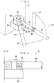
- Fig. 2 is an enlarged perspective view showing handle portion of the aforesaid embodiment;
- Fig. 3 is a cross section of the handle portion of Fig. 2;
- Fig. 4 is a block diagram of the aforesaid embodiment;
- Fig. 5 is an illustration of a process for measuring inner diameter of a hole in the aforesaid embodiment;
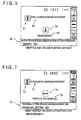
- Fig. 6 is an illustration showing a probe lowering step screen in measuring inner diameter of a hole;
- Fig. 7 is an illustration showing a profiling measurement step screen in measuring inner diameter of a hole;
- Fig. 8 is an illustration showing a probe raising step screen in measuring inner diameter of a hole;
- Fig. 9 is an illustration showing a profiling measurement step screen in measuring inner diameter of a hole;
- Fig. 10 is an illustration showing a measurement result screen in measuring inner diameter of a hole;
- Fig. 11 is an illustration showing consecutive measurement step of an inner diameter of a plurality of hole; and
- Fig. 12 is a perspective view showing measurement work of a conventional height gauge.
-
- An embodiment of the present invention will be described below with reference to attached drawings.
- Fig. 1 is a perspective view of a height gauge (measuring equipment) of the present embodiment. As shown in the figure, the height gauge according to the present embodiment includes a base 11 movably disposed on a
platen 10, acolumn 12 vertically disposed on the base 11, aslider 14 elevatable in up and down direction along thecolumn 12 and having aprobe 13, agrip portion 15 provided to the base 11 opposite to thecolumn 12, adisplay console 18 provided to an upside of thegrip portion 15 and having adisplay 16 such as LCD and akey input portion 17 on a surface thereof, and an air-floatation mechanism 19 for blowing out air from the base 11 to theplaten 10 to float the base 11 relative to theplaten 10. - The air-
floatation mechanism 19 includes a plurality ofair pad 19A provided to a lower side of the base 11 and having a number of air blowout hole, and a compressor for feeding air to theair pad 19A (though not shown, provided to a lower part of the grip portion 15). - The air-
floatation mechanism 19 can change rotational frequency of a motor for driving the compressor, thus being capable of switching status thereof between a status where the base 11 is completely floated with a predetermined gap against theplaten 10 by blowing out the air from the base 11 to theplaten 10, and a semi-floating status where the base 11 touches theplaten 10 with a weight of the base 11 and a weight applied to the base 11 being reduced by blowing out an air from the base 11 to theplaten 10. - A
handle 21 projects from a right side of the column 12 (i.e. a side adjacent to a side having the probe 13) adjacent to the base 11 (i.e. lower position) orthogonally with thecolumn 12. - As shown in Fig. 2 and Fig. 3, the
handle 21 is composed of astationary member 23 fixed to a lower part of the right side of thecolumn 12 and having apivot axis 22 on an upper side thereof, arotary ring 24 rotatable around thepivot axis 22, arotary shaft 25 screwed to an outer circumference of therotary ring 24 with an end being capable of abutting and separating relative to thepivot axis 22, and aninclining shaft 27 provided to an end of therotary shaft 25 capable of being inclined in up and down direction through a bolt/nut 26. Accordingly, thehandle 21 can rotate around thepivot axis 22 parallel to thecolumn 12 and being fixed at any rotary angle position, and at least theinclining shaft 27 at an end is capable of being inclined in up and down direction and capable of being fixed at any inclination angle position. - An air-
floatation switch 31, arepeat switch 32 and acancel switch 33 are provided to therotary shaft 25 sequentially from theinclination shaft 27 side to a base thereof. - The air-floatation switch 31 controls supply and cut-off of the air toward the air-
floatation mechanism 19. Therepeat switch 32 repeatingly commands a measurement process in a previous measurement item. Thecancel switch 33 commands cancellation of the measurement process now in progress. - Fig. 4 is a block diagram of a height gauge of the present invention. In the figure, a
controller 41 has aCPU 42 and amemory 43. - An elevation driving means 44 for elevating the
slider 14 in up and down direction, adisplacement sensor 45 for detecting a height displacement of theslider 14 elevated by the elevation driving means 44 and aspeaker 46 are connected to theCPU 42 as well as thekey input portion 17, threeswitches handle 21, thedisplay 16 and the air-floatation mechanism 19. - The elevation driving means 44 includes a lifting
motor 44A and aconstant pressure mechanism 44B provided to an output shaft of the liftingmotor 44A. Theconstant pressure mechanism 44B transmits the rotation of the liftingmotor 44A to theslider 14 through a transmission of belt etc. to elevate theslider 14 and includes a mechanism for idly running when a load exceeding a predetermined value is applied to theslider 14. - The
displacement sensor 45 includes a scale having an optical grid provided along thecolumn 12 and a sensor disposed on theslider 14 opposite to the scale, both the scale and the sensor cooperating to detect the height displacement amount of theslider 14 on thecolumn 12 as an electric signal. - Measurement process program for various measurement item is stored in the
memory 43, and symbol and character data representing content of the measurement item, symbol and character data representing respective steps, operation guidance information and voice information indicating completion of respective steps are stored in accordance with the respective steps of the respective measurement process program. Further, measurement data and calculation result data obtained by operating the measurement data are stored in thememory 43. - Next, a function of the present embodiment will be described below.
- In initiating measurement, the
handle 21 is grasped with one hand and the air-floatation control switch 31 is pressed by a thumb of the hand. Then, the base 11 floats relative to theplaten 10 by the air-floatation mechanism 19 so that the base 11 is moved with thehandle 21 being grasped to locate theprobe 13 adjacent to a target portion of the workpiece while being floated, and the hand is released from the air-floatation control switch 31. Accordingly, since the air is cut off, the base 11 rests while touching theplaten 10. - Measurement of an inner dimension of a hole of a workpiece will be described below as an example.
- In measuring the inner dimension of a hole, the
probe 13 is inserted into the hole and measurement initiation is commanded from thekey input portion 17. TheCPU 42 drives the elevation driving means 44 to lower theslider 14. Then, theprobe 13 descends as shown in (1) of Fig. 5. Incidentally, H in Fig. 5 represents the hole of the workpiece. - At this time, a screen shown in Fig. 6 is displayed on the
display 16. Specifically, circle (hole) measurement item is indicated by asymbol 61 andcharacter data 62, probe lowering step is indicated by asymbol 63 andcharacter data 64 and operation guidance information 65 (information that profiling measurement can be started by pressing [ENTER] key) is displayed on a lower column. - Subsequently, when the
probe 13 detects contact with a lower wall of the hole H (see (1) of Fig. 5), a contact completion sound is outputted, thus finishing the probe lowering step. - Next, after terminating the probe lowering step, the screen of Fig. 7 is displayed on the
display 16. Specifically, circle (hole) measurement item is indicated by asymbol 71 andcharacter data 72, profiling measurement step is indicated by asymbol 73 andcharacter data 74 and operation guidance information 75 (information that profiling measurement can be terminated by pressing [ENTER] key) is displayed on a lower column. - The worker conducts the profiling measurement in view of the indication. More specifically, the worker moves the base 11 of the height gauge to move the
probe 13 in a diameter direction of the hole H of the workpiece. Specifically, theprobe 13 is moved as shown in (2) of Fig. 5. Then, a Z coordinate value when theprobe 13 is located to a lowermost point of the hole H is fetched and a profiling completion sound is outputted after movement of a predetermined distance from the position to finish the profiling measurement step. Incidentally, since the air-floatation mechanism 19 has been switched into a semi-floating status, movement thereof is easy without deteriorating measurement accuracy. - Subsequently, when the profiling measurement step is finished, the CPU42 drives the elevation driving means 44 to raise the
slider 14. Then, theprobe 13 is raised as shown in (3) of Fig. 5. - During the step, the
display 16 shows a screen shown in Fig. 8. Specifically, circle (hole) measurement item is indicated by asymbol 81 andcharacter data 82, probe raising step is indicated by a symbol 83 andcharacter data 84 and operation guidance information 85 (information that profiling measurement can be initiated by pressing [ENTER] key) is displayed on a lower column. - Subsequently, when the
probe 13 detects contact with an upper wall of the hole H (see (3) of Fig. 5), a contact completion sound is outputted, thus finishing the probe raising step. - Next, when the probe raising step is terminated, the
display 16 shows a screen shown in Fig. 9. Specifically, circle (hole) measurement item is indicated by asymbol 91 andcharacter data 92, profiling measurement step is indicated by asymbol 93 andcharacter data 94 and operation guidance information 95 (information that profiling measurement can be initiated by pressing [ENTER] key) is displayed on a lower column. - The worker conducts the profiling measurement in view of the indication. More specifically, the worker moves the base 11 of the height gauge to move the
probe 13 in a diameter direction of the hole H of the workpiece. Specifically, theprobe 13 is moved as shown in (4) of Fig. 5. Then, a Z coordinate value when theprobe 13 is located to a lowermost point of the hole H is fetched and a profiling completion sound is outputted after movement of a predetermined distance from the position to finish the profiling measurement step. Incidentally, since the air-floatation mechanism 19 has also been switched into a semi-floating status, movement thereof is easy without deteriorating measurement accuracy. - Next, when the profiling measurement step is terminated, the
display 16 shows a screen shown in Fig. 10. Specifically, circle (hole) measurement item is indicated by asymbol 101 andcharacter data 102, central coordinate value Z and diameter D of the hole obtained by the measurement item is indicated, and operation guidance information 105 (information that profiling measurement can be initiated by pressing [ENTER] key) is displayed on a lower column. - The inner diameter of the hole H can be measured according to the above respective steps. However, as shown in Fig. 11, in order to consecutively measure two holes H1 and H2, height difference h between the two holes H1 and H2 may be registered in advance, and a "wait indication may be displayed on the
display 16 when the measurement of the hole H1 is terminated and a message to the effect that theprobe 13 is pulled out from the hole H1 of the workpiece may be displayed, thus instructing the next work to the worker. - Subsequently, after automatically raising the
probe 13 by the previously registered difference h after a predetermined time period, the "wait indication" may be displayed on thedisplay 16 and a message to the effect that theprobe 13 is inserted to the hole H2 of the workpiece may be displayed, thereby instructing the next work to the worker. - Accordingly, consecutive measurement of the plurality of holes H1 and H2 can be conducted while giving instructions to the worker.
- According to the present embodiment, since the
handle 21 is provided to the lower side position of thecolumn 12, thehandle 21 can be grasped with an easy posture while checking whether theprobe 13 has reached adjacent to the target portion of the workpiece, thus improving operability thereof during movement. - Since the
handle 21 is provided to thecolumn 12, any special member for securing a height from theplaten 10 to thehandle 21 is necessary for establishing desired height. For instance, when thehandle 21 is provided to the base 11, thickness of the base 11 has to be increased or an additional member on the base 11 for securing height is necessary. However, since thehandle 21 is provided to thecolumn 12, any special member is necessary and desired height from theplaten 10 to thehandle 21 can be established. - Since the
handle 21 is provided with the air-floatation control switch 31 for controlling supply and cut-off of the air to the air-floatation mechanism 19, therepeat switch 32 for repeatingly commanding the measurement process and the cancelswitch 33 sequentially aligned from a grip side, theswitches handle 21. Accordingly, the base 11 can be moved and stopped, and consecutive measurement and cancel operation are possible with a single-hand operation, thereby improving measurement efficiency. - Since the
handle 21 includes therotary shaft 25 rotatable around thepivot axis 22 parallel to thecolumn 12 and fixable at a desired rotary angle position, and the incliningshaft 27 provided at an end of therotary shaft 25 inclinable in up and down direction, therotary shaft 25 can be rotated around thepivot axis 22 to change an angle of thehandle 21 for improving operability and the incliningshaft 27 can be inclined in up and down direction to prevent from being projected to a horizontal direction, thus not being an obstacle for accommodation and portability. - Further, since the status of the air-
floatation mechanism 19 can be switched between a status where the base 11 is completely floated against theplaten 10 with a predetermined gap therebetween by blowing air from the base 11 to theplaten 10 and the semi-floating status where the base 11 touches theplaten 10 while reducing the weight of the base 11 and the weight applied to the base 11 by blowing air from the base 11 to theplaten 10, the movement can be facilitated during, for instance, profiling measurement by measuring under the semi-floating status with high-accuracy being maintained. - Further, since the
handle 21 is provided for the movement, the movement is possible with thehandle 21 being grasped at an easy posture while confirming that theprobe 13 touches the target portion of the workpiece, though heavy as compared to completely floated status. In other words, operability during the profiling measurement can be improved. - Incidentally, though the
handle 21 is projected at the lower right side of thecolumn 12 in the aforesaid embodiment, thehandle 21 may be provided to a lower left side, or selectively to either one of the right and left sides. Further, thehandle 21 may be projected to both sides of thecolumn 21 in advance. - The member to which the
handle 21 is attached is not limited to thecolumn 12 but may be provided on the base 11 around a side adjacent to theprobe 13 side of thecolumn 12. However, when thehandle 21 is provided to thecolumn 12, no special member for securing the height from theplaten 10 to thehandle 21 is not required, so that desired height setting is possible. - Further, though the
handle 21 in the aforesaid embodiment includes therotary shaft 25 rotatable around thepivot axis 22 parallel to thecolumn 12 and fixable at a desired rotary angle position, and the incliningshaft 27 provided at an end of therotary shaft 25 inclinable in up and down direction, other arrangement is possible. - For instance, the
handle 21 may be rotatable in front, back, up and down direction and fixable at any desired angle position with a ball joint etc. Or, alternatively, thehandle 21 may be constructed of a shaft member and a plurality of shaft member separably connected in an axial direction for adjusting length thereof.
Claims (6)
- A height gauge comprising: a base movable on a platen;a column vertically provided on the base;a slider elevatable along the column and having a probe thereto;a displacement sensor for detecting a displacement amount of the slider in a height direction;an air-floatation mechanism for floating the base against the platen by blowing out air from the base to the platen; anda handle on a side of the column adjacent to a probe side thereof around the base or on a base around the side of the column adjacent to the probe side, the handle having an air-floatation control switch for controlling supply and cut-off of air to the air-floatation mechanism.
- The height gauge according to Claim 1, the handle further comprising a repeat switch for repeatingly commanding measurement steps of a previous measurement item.
- The height gauge according to Claim 1 or 2, the handle further comprising a cancel switch for commanding cancellation of the measurement step currently in process.
- The height gauge according to any one of Claims 1 to 3, wherein the handle is rotatable around an axis parallel to the column and fixable at any desired rotary angle position.
- The height gauge according to Claim 4, wherein at least an end portion of the handle is inclinable in up and down direction and fixable at any desired inclination angle position.
- The height gauge according to any one of Claims 1 to 5, wherein the air-floatation mechanism is capable of switching status thereof between a status in which the base is completely floated against the platen with a predetermined gap therebetween by blowing air from the base to the platen and a semi-floating status in which the base touches the platen with a weight of the base and a weight applied to the base being reduced by blowing air from the base to the platen.
Applications Claiming Priority (2)
| Application Number | Priority Date | Filing Date | Title |
|---|---|---|---|
| JP1194099 | 1999-01-20 | ||
| JP01194099A JP4009379B2 (en) | 1999-01-20 | 1999-01-20 | Height gauge |
Publications (3)
| Publication Number | Publication Date |
|---|---|
| EP1022538A2 EP1022538A2 (en) | 2000-07-26 |
| EP1022538A3 EP1022538A3 (en) | 2001-02-14 |
| EP1022538B1 true EP1022538B1 (en) | 2002-07-03 |
Family
ID=11791657
Family Applications (1)
| Application Number | Title | Priority Date | Filing Date |
|---|---|---|---|
| EP00101077A Expired - Lifetime EP1022538B1 (en) | 1999-01-20 | 2000-01-20 | Height gauge with air floatation handle |
Country Status (5)
| Country | Link |
|---|---|
| US (1) | US6357134B1 (en) |
| EP (1) | EP1022538B1 (en) |
| JP (1) | JP4009379B2 (en) |
| CN (2) | CN1155804C (en) |
| DE (1) | DE60000241T2 (en) |
Families Citing this family (26)
| Publication number | Priority date | Publication date | Assignee | Title |
|---|---|---|---|---|
| JP4009379B2 (en) * | 1999-01-20 | 2007-11-14 | 株式会社ミツトヨ | Height gauge |
| US6401352B1 (en) * | 1999-10-01 | 2002-06-11 | Mitutoyo Corporation | Linear measuring machine |
| EP1241436B1 (en) * | 2001-03-14 | 2014-11-19 | Tesa Sa | Coordinate measuring machine and method for introducing a command to change the measurement mode in this machine |
| US6655038B1 (en) * | 2001-09-04 | 2003-12-02 | Howard W. Grivna | Work station set-up gauge with remote readout |
| DE102006029290B4 (en) * | 2006-06-23 | 2013-12-24 | Andreas Reichhardt | Electromechanical sensing device for distance detection |
| KR100786524B1 (en) | 2006-07-19 | 2007-12-17 | 엘지전자 주식회사 | Vessel height measuring device and method and liquid dispenser using same |
| CN101709942B (en) * | 2009-12-11 | 2011-09-21 | 奇瑞汽车股份有限公司 | Multifunctional height gauge |
| CN103162672B (en) * | 2011-12-15 | 2015-06-10 | 鸿富锦精密工业(武汉)有限公司 | Measuring apparatus |
| CN102706300B (en) * | 2012-06-11 | 2014-10-22 | 卓越(苏州)自动化设备有限公司 | Height detecting device |
| US9903701B2 (en) * | 2014-05-14 | 2018-02-27 | Faro Technologies, Inc. | Articulated arm coordinate measurement machine having a rotary switch |
| US9921046B2 (en) | 2014-05-14 | 2018-03-20 | Faro Technologies, Inc. | Metrology device and method of servicing |
| US9829305B2 (en) | 2014-05-14 | 2017-11-28 | Faro Technologies, Inc. | Metrology device and method of changing operating system |
| US9803969B2 (en) | 2014-05-14 | 2017-10-31 | Faro Technologies, Inc. | Metrology device and method of communicating with portable devices |
| US9746308B2 (en) | 2014-05-14 | 2017-08-29 | Faro Technologies, Inc. | Metrology device and method of performing an inspection |
| CN104764383A (en) * | 2015-03-20 | 2015-07-08 | 奇瑞汽车股份有限公司 | Height measuring tool for automobile pedal face |
| CN105547226B (en) * | 2015-12-23 | 2018-06-05 | 博众精工科技股份有限公司 | It is a kind of apart from testing agency |
| CN105758352B (en) * | 2016-04-21 | 2019-11-05 | 博众精工科技股份有限公司 | A kind of measurement component |
| US10274308B2 (en) | 2017-04-18 | 2019-04-30 | United Technologies Corporation | Precision optical height gauge |
| FR3077347B1 (en) * | 2018-01-30 | 2020-02-28 | Airbus Operations | DEVICE AND METHOD FOR CONTROLLING SCREW AND NUT ASSEMBLIES IN AN AIRCRAFT |
| JP7071891B2 (en) * | 2018-07-17 | 2022-05-19 | 株式会社ミツトヨ | Height gauge |
| JP7261560B2 (en) * | 2018-10-31 | 2023-04-20 | 株式会社ミツトヨ | Surface texture measuring method and surface texture measuring device |
| JP7252839B2 (en) * | 2019-06-21 | 2023-04-05 | 株式会社ミツトヨ | height gauge |
| JP7267875B2 (en) * | 2019-08-29 | 2023-05-02 | 株式会社ミツトヨ | 1D measuring machine |
| JP7658756B2 (en) * | 2021-02-26 | 2025-04-08 | 株式会社ミツトヨ | One-dimensional measuring machine and its control program |
| JP2022131934A (en) * | 2021-02-26 | 2022-09-07 | 株式会社ミツトヨ | 1D measuring machine and control program for 1D measuring machine |
| JP2024037476A (en) * | 2022-09-07 | 2024-03-19 | 株式会社ミツトヨ | One-dimensional measuring machine and one-dimensional measuring machine control program |
Family Cites Families (7)
| Publication number | Priority date | Publication date | Assignee | Title |
|---|---|---|---|---|
| US3895356A (en) * | 1973-10-10 | 1975-07-15 | Kraus Instr Inc | Automatic digital height gauge |
| US4129949A (en) * | 1976-04-05 | 1978-12-19 | Brown & Sharpe Manufacturing Company | Height gage |
| GB2042732B (en) | 1979-02-07 | 1983-05-05 | Eley & Warren Precision Engs C | Height measuring device |
| JPS6123766Y2 (en) | 1980-10-24 | 1986-07-16 | ||
| GB2110371B (en) * | 1981-08-10 | 1985-01-30 | Mitutoyo Mfg Co Ltd | Height gauge |
| US4679326A (en) * | 1984-11-21 | 1987-07-14 | Mitutoyo Mfg. Co., Ltd. | Height gauge |
| JP4009379B2 (en) * | 1999-01-20 | 2007-11-14 | 株式会社ミツトヨ | Height gauge |
-
1999
- 1999-01-20 JP JP01194099A patent/JP4009379B2/en not_active Expired - Fee Related
-
2000
- 2000-01-18 US US09/484,224 patent/US6357134B1/en not_active Expired - Lifetime
- 2000-01-19 CN CNB001016210A patent/CN1155804C/en not_active Expired - Fee Related
- 2000-01-19 CN CNB2004100351606A patent/CN1324300C/en not_active Expired - Lifetime
- 2000-01-20 DE DE60000241T patent/DE60000241T2/en not_active Expired - Lifetime
- 2000-01-20 EP EP00101077A patent/EP1022538B1/en not_active Expired - Lifetime
Also Published As
| Publication number | Publication date |
|---|---|
| CN1324300C (en) | 2007-07-04 |
| EP1022538A3 (en) | 2001-02-14 |
| DE60000241T2 (en) | 2002-10-24 |
| DE60000241D1 (en) | 2002-08-08 |
| EP1022538A2 (en) | 2000-07-26 |
| US6357134B1 (en) | 2002-03-19 |
| JP2000213905A (en) | 2000-08-04 |
| CN1540284A (en) | 2004-10-27 |
| JP4009379B2 (en) | 2007-11-14 |
| CN1261659A (en) | 2000-08-02 |
| CN1155804C (en) | 2004-06-30 |
Similar Documents
| Publication | Publication Date | Title |
|---|---|---|
| US6357134B1 (en) | Height gauge | |
| US6446351B1 (en) | Linear measuring machine | |
| JP3629461B2 (en) | How to enter commands to switch dimension measurement columns and their measurement modes | |
| US10605583B2 (en) | Drive control method of drive stage device | |
| CN111121597B (en) | Surface texture measuring method and surface texture measuring device | |
| JP3482362B2 (en) | Surface texture measuring device, inclination adjusting device for surface texture measuring device, and method of adjusting posture of measurement object in surface texture measuring device | |
| JPH0419461Y2 (en) | ||
| JP2007198791A (en) | Surface texture measuring machine | |
| JP2569390B2 (en) | Roundness measuring machine | |
| JP2000213928A (en) | Circle measuring device, and limit value detector | |
| JP3434189B2 (en) | Material testing machine | |
| JP3696431B2 (en) | One-dimensional measuring machine | |
| JP2827097B2 (en) | Teach position teaching method of robot welding gun | |
| JP7227527B2 (en) | Coordinate measuring machine, measuring method, and measuring program | |
| JPH06270059A (en) | Grinding reference plane position detecting device for grinding robot | |
| JP2002221414A (en) | One-dimensional measuring device | |
| JP3019987B2 (en) | Automatic dimension measuring device | |
| JPH0346862Y2 (en) | ||
| JPH08101031A (en) | Method and device for driving probe of coordinate measuring machine | |
| JP7071891B2 (en) | Height gauge | |
| US20240269763A1 (en) | Device for measuring wear amount of welding tip, control device, robot system, method, and computer program | |
| JP2603167Y2 (en) | Positioning device for sizing device | |
| JPH06270060A (en) | Grinding reference plane position detecting device for grinding robot | |
| JPH06300559A (en) | Aligning method and device for measurement object in roundness measurement instrument | |
| JP2002228435A (en) | Measuring method with tolerance collating function |
Legal Events
| Date | Code | Title | Description |
|---|---|---|---|
| PUAI | Public reference made under article 153(3) epc to a published international application that has entered the european phase |
Free format text: ORIGINAL CODE: 0009012 |
|
| AK | Designated contracting states |
Kind code of ref document: A2 Designated state(s): DE FR GB IT |
|
| AX | Request for extension of the european patent |
Free format text: AL;LT;LV;MK;RO;SI |
|
| PUAL | Search report despatched |
Free format text: ORIGINAL CODE: 0009013 |
|
| AK | Designated contracting states |
Kind code of ref document: A3 Designated state(s): AT BE CH CY DE DK ES FI FR GB GR IE IT LI LU MC NL PT SE |
|
| AX | Request for extension of the european patent |
Free format text: AL;LT;LV;MK;RO;SI |
|
| 17P | Request for examination filed |
Effective date: 20010319 |
|
| GRAG | Despatch of communication of intention to grant |
Free format text: ORIGINAL CODE: EPIDOS AGRA |
|
| 17Q | First examination report despatched |
Effective date: 20010705 |
|
| AKX | Designation fees paid |
Free format text: DE FR GB IT |
|
| GRAG | Despatch of communication of intention to grant |
Free format text: ORIGINAL CODE: EPIDOS AGRA |
|
| GRAH | Despatch of communication of intention to grant a patent |
Free format text: ORIGINAL CODE: EPIDOS IGRA |
|
| GRAH | Despatch of communication of intention to grant a patent |
Free format text: ORIGINAL CODE: EPIDOS IGRA |
|
| GRAA | (expected) grant |
Free format text: ORIGINAL CODE: 0009210 |
|
| AK | Designated contracting states |
Kind code of ref document: B1 Designated state(s): DE FR GB IT |
|
| REF | Corresponds to: |
Ref document number: 60000241 Country of ref document: DE Date of ref document: 20020808 |
|
| RIN2 | Information on inventor provided after grant (corrected) |
Free format text: HAMA, NOBUYUKI, C/O MITUTOYO CORPORATION * TOIDA, YOICHI, C/O MITUTOYO CORPORATION * ZHANG, YUWU, C/O MITUTOYO CORPORATION |
|
| ET | Fr: translation filed | ||
| PLBE | No opposition filed within time limit |
Free format text: ORIGINAL CODE: 0009261 |
|
| STAA | Information on the status of an ep patent application or granted ep patent |
Free format text: STATUS: NO OPPOSITION FILED WITHIN TIME LIMIT |
|
| 26N | No opposition filed |
Effective date: 20030404 |
|
| REG | Reference to a national code |
Ref country code: FR Ref legal event code: PLFP Year of fee payment: 17 |
|
| REG | Reference to a national code |
Ref country code: FR Ref legal event code: PLFP Year of fee payment: 18 |
|
| REG | Reference to a national code |
Ref country code: FR Ref legal event code: PLFP Year of fee payment: 19 |
|
| PGFP | Annual fee paid to national office [announced via postgrant information from national office to epo] |
Ref country code: IT Payment date: 20190124 Year of fee payment: 20 Ref country code: FR Payment date: 20190123 Year of fee payment: 20 Ref country code: GB Payment date: 20190121 Year of fee payment: 20 Ref country code: DE Payment date: 20190123 Year of fee payment: 20 |
|
| REG | Reference to a national code |
Ref country code: DE Ref legal event code: R071 Ref document number: 60000241 Country of ref document: DE |
|
| REG | Reference to a national code |
Ref country code: GB Ref legal event code: PE20 Expiry date: 20200119 |
|
| PG25 | Lapsed in a contracting state [announced via postgrant information from national office to epo] |
Ref country code: GB Free format text: LAPSE BECAUSE OF EXPIRATION OF PROTECTION Effective date: 20200119 |