EP1022081A2 - Cutting device, processing equipment, and cutting method - Google Patents
Cutting device, processing equipment, and cutting method Download PDFInfo
- Publication number
- EP1022081A2 EP1022081A2 EP00100266A EP00100266A EP1022081A2 EP 1022081 A2 EP1022081 A2 EP 1022081A2 EP 00100266 A EP00100266 A EP 00100266A EP 00100266 A EP00100266 A EP 00100266A EP 1022081 A2 EP1022081 A2 EP 1022081A2
- Authority
- EP
- European Patent Office
- Prior art keywords
- impacting body
- cutting
- cutting device
- processed
- impact
- Prior art date
- Legal status (The legal status is an assumption and is not a legal conclusion. Google has not performed a legal analysis and makes no representation as to the accuracy of the status listed.)
- Withdrawn
Links
Images



Classifications
-
- B—PERFORMING OPERATIONS; TRANSPORTING
- B26—HAND CUTTING TOOLS; CUTTING; SEVERING
- B26D—CUTTING; DETAILS COMMON TO MACHINES FOR PERFORATING, PUNCHING, CUTTING-OUT, STAMPING-OUT OR SEVERING
- B26D3/00—Cutting work characterised by the nature of the cut made; Apparatus therefor
-
- C—CHEMISTRY; METALLURGY
- C03—GLASS; MINERAL OR SLAG WOOL
- C03B—MANUFACTURE, SHAPING, OR SUPPLEMENTARY PROCESSES
- C03B33/00—Severing cooled glass
- C03B33/10—Glass-cutting tools, e.g. scoring tools
- C03B33/105—Details of cutting or scoring means, e.g. tips
- C03B33/107—Wheel design, e.g. materials, construction, shape
-
- B—PERFORMING OPERATIONS; TRANSPORTING
- B02—CRUSHING, PULVERISING, OR DISINTEGRATING; PREPARATORY TREATMENT OF GRAIN FOR MILLING
- B02C—CRUSHING, PULVERISING, OR DISINTEGRATING IN GENERAL; MILLING GRAIN
- B02C13/00—Disintegrating by mills having rotary beater elements ; Hammer mills
- B02C13/26—Details
- B02C13/28—Shape or construction of beater elements
-
- B—PERFORMING OPERATIONS; TRANSPORTING
- B02—CRUSHING, PULVERISING, OR DISINTEGRATING; PREPARATORY TREATMENT OF GRAIN FOR MILLING
- B02C—CRUSHING, PULVERISING, OR DISINTEGRATING IN GENERAL; MILLING GRAIN
- B02C18/00—Disintegrating by knives or other cutting or tearing members which chop material into fragments
- B02C18/06—Disintegrating by knives or other cutting or tearing members which chop material into fragments with rotating knives
- B02C18/16—Details
- B02C18/18—Knives; Mountings thereof
-
- B—PERFORMING OPERATIONS; TRANSPORTING
- B28—WORKING CEMENT, CLAY, OR STONE
- B28D—WORKING STONE OR STONE-LIKE MATERIALS
- B28D1/00—Working stone or stone-like materials, e.g. brick, concrete or glass, not provided for elsewhere; Machines, devices, tools therefor
- B28D1/18—Working stone or stone-like materials, e.g. brick, concrete or glass, not provided for elsewhere; Machines, devices, tools therefor by milling, e.g. channelling by means of milling tools
- B28D1/181—Working stone or stone-like materials, e.g. brick, concrete or glass, not provided for elsewhere; Machines, devices, tools therefor by milling, e.g. channelling by means of milling tools using cutters loosely mounted on a turning tool support
-
- B—PERFORMING OPERATIONS; TRANSPORTING
- B28—WORKING CEMENT, CLAY, OR STONE
- B28D—WORKING STONE OR STONE-LIKE MATERIALS
- B28D1/00—Working stone or stone-like materials, e.g. brick, concrete or glass, not provided for elsewhere; Machines, devices, tools therefor
- B28D1/18—Working stone or stone-like materials, e.g. brick, concrete or glass, not provided for elsewhere; Machines, devices, tools therefor by milling, e.g. channelling by means of milling tools
- B28D1/186—Tools therefor, e.g. having exchangeable cutter bits
-
- C—CHEMISTRY; METALLURGY
- C03—GLASS; MINERAL OR SLAG WOOL
- C03B—MANUFACTURE, SHAPING, OR SUPPLEMENTARY PROCESSES
- C03B33/00—Severing cooled glass
- C03B33/06—Cutting or splitting glass tubes, rods, or hollow products
-
- B—PERFORMING OPERATIONS; TRANSPORTING
- B02—CRUSHING, PULVERISING, OR DISINTEGRATING; PREPARATORY TREATMENT OF GRAIN FOR MILLING
- B02C—CRUSHING, PULVERISING, OR DISINTEGRATING IN GENERAL; MILLING GRAIN
- B02C13/00—Disintegrating by mills having rotary beater elements ; Hammer mills
- B02C13/26—Details
- B02C13/28—Shape or construction of beater elements
- B02C2013/2808—Shape or construction of beater elements the beater elements are attached to disks mounted on a shaft
-
- Y—GENERAL TAGGING OF NEW TECHNOLOGICAL DEVELOPMENTS; GENERAL TAGGING OF CROSS-SECTIONAL TECHNOLOGIES SPANNING OVER SEVERAL SECTIONS OF THE IPC; TECHNICAL SUBJECTS COVERED BY FORMER USPC CROSS-REFERENCE ART COLLECTIONS [XRACs] AND DIGESTS
- Y10—TECHNICAL SUBJECTS COVERED BY FORMER USPC
- Y10T—TECHNICAL SUBJECTS COVERED BY FORMER US CLASSIFICATION
- Y10T83/00—Cutting
- Y10T83/768—Rotatable disc tool pair or tool and carrier
- Y10T83/7684—With means to support work relative to tool[s]
- Y10T83/7688—Plural tool elements successively actuated at same station
Definitions
- the present invention relates to a cutting device that can cut an object formed of a single member, such as glass, ceramics, resin, metal, or the like, or a composite member thereof continuously using one kind of cutting tool. More particularly, the present invention relates to a cutting device that cuts an object while smashing the very surface area of the object by allowing an impacting body formed of a hard solid body to impact on the object at a high speed with a high frequency, and to a cutting method using the same.
- CRT glass a cathode-ray tube
- methods used for cutting and disassembling glass used in a cathode-ray tube (CRT) for the purpose of its recycling include a method of utilizing the thermal shock obtained by winding a heater wire around the CRT and energizing the heater wire to heat the CRT, a cutting method of using a diamond wheel cutter that is rotated at a high speed, a gas fusion cutting method (a method of melting and cutting glass using a gas), or the like.
- sheet steel pieces (cold rolled steel plate sheets and strips cut to length or the like) forming bodies of automobiles and case bodies or other components of various household electric appliances are cut by a band-shaped cutter (a band saw machine) or a disc-shaped cutter (a metal slitting saw), which is provided with a high hardness saw blade, by a grinder cutting method using a grinding tool in which abrasive grains are formed in a disc shape or in a cylindrical shape, or by a gas fusion cutting method using an acetylene gas or the like.
- a band-shaped cutter a band saw machine
- a disc-shaped cutter a metal slitting saw
- resin-molded articles are cut by a band saw machine, a metal slitting saw, an end mill, or the like.
- the present invention puts a theory to practical use in a cutting device.
- the theory is a plastic wave theory in which when a high-speed tensile force is applied at least at a critical impact velocity, a fracture occurs immediately at the part where the force has been applied, or a theory in which when a high-speed compressive force is applied at least at a critical impact velocity, the ductility is deteriorated rapidly and thus the part where the force has been applied is broken even by a small distortion (a phenomenon similar to the embrittlement).
- a cutting device replaces a conventional tool provided with a blade, and in the cutting device an impacting body formed of a hard solid body such as metal is allowed to impact on an object to be cut (hereinafter referred to as "an object to be processed” or "a work") at a very high speed with a high frequency to generate a plastic wave by the impact energy, thus breaking and removing the part subjected to the impact instantaneously.
- an object to be processed an object to be processed
- a work an impacting body formed of a hard solid body such as metal
- the present invention provides a cutting device based on the following principle: when an impacting body that executes a high speed circular motion impacts on a work at least at the critical impact velocity of the work and then rebounds, the surface of the work in a highly limited area including the part subjected to the impact by the impacting body and its vicinity is smashed (broken) instantaneously into a minute granular state or minute fragments by a high speed compression that occurs together with impact, a high speed tension due to friction, high speed shearing, or the like.
- the impacting body is required to impact on a work at least at the critical impact velocity of the work.
- the impact velocity is set to be at least about 139 m/second (about 500 km/hour), more preferably at least about 340 m/second (about 1224 km/hour).
- the above-mentioned impact velocities correspond to rotational speeds of at least 26,500 rpm and of at least 65,130 rpm, respectively.
- the critical impact velocity varies depending on the kind of a work.
- the critical impact velocities of aluminum, soft steel, stainless steel, and titanium are about 49.7 m/second, 30.0 m/second, 152.3 m/second, and 61.8 m/second, respectively. Therefore, the impact velocity of the impacting body can be changed according to the kind of a work. It is preferred to set the impact velocity of the impacting body to be at least twice, further preferably at least three times, and particularly preferably at least four times as high as the critical impact velocity of the work, because this enables stable cutting.
- the impacting body has a through hole and is maintained rotatably by a spindle provided perpendicularly on the rotor with a predetermined fitting gap being provided between the impacting body and the spindle.
- a fitting gap By providing the fitting gap, the displacement of the impacting body that occurs right after the impacting body has impacted on a work can be absorbed.
- the fitting gap between the spindle for supporting the impacting body and the through hole of the impacting body is set to be at least 2 mm, more preferably about 5 to 10 mm. It is necessary to set the fitting gap to be larger corresponding to the increase in impact velocity of the impacting body.
- the fitting gap according to the present invention is far beyond the gap value according to the Japanese Industrial Standard (JIS), which generally defines the fitting state between an axis and a bearing, and is two to three orders of magnitude larger than the gap value.
- JIS Japanese Industrial Standard
- the processing principle of the present invention is different from a conventional processing principle by utilizing impact.
- a cutting blade of a cutting tool is allowed to collide with a work at a low speed (a maximum of about 10 m/second) and the work is deformed in a sequence from elastic deformation to breakage through plastic deformation, thus breaking the surface of the work in a relatively large area.
- the impacting body of the present invention is not provided with a sharp cutting blade as in the conventional cutting tool.
- the cutting according to the present invention is characterized as follows.
- the cutting device of the present invention has a simple configuration and can achieve the increase in life span and the great improvement in reliability.
- the cutting device of the present invention is extremely useful as a smashing or cutting device that is a part of recycling equipment.
- the present invention can automate scrapping and cutting processes of household electric appliances, automobiles, or the like for the purpose of disposal. According to the present invention, it is not necessary to change the type of cutting tool, processing conditions, or a cutting device according to the kind of an object to be processed or members included in the object.
- the present invention contributes to the improvement in reliability the increase in life span of the cutting device and in recycling ratio, the environmental protection, and the efficient use of natural resources.
- a first aspect of the present invention provides a cutting device characterized in that an impacting body is mounted rotatably to a spindle that is provided perpendicularly on a principal plane of a rotor, and the rotor is rotated at a high speed to allow the impacting body to impact on an object to be processed (a work) at least at the critical impact velocity of the object.
- This cutting device reduces the abrasion of a cutting blade by the impact cutting utilizing a centrifugal force, thus achieving the increase in life span and the improvement in reliability of the cutting device.
- the cutting device has no preference for the kind of the object to be processed and enables high speed smashing or high speed cutting.
- a second aspect provides a cutting device characterized in that a spindle is provided between a pair of rotors whose principal planes oppose each other, an impacting body is mounted to the spindle rotatably, and the pair of rotors are rotated at a high speed to allow the impacting body to impact on an object to be processed (a work) at least at the critical impact velocity of the object.
- This cutting device reduces the abrasion of a cutting blade by the impact cutting utilizing a centrifugal force, thus achieving the increase in life span and the improvement in reliability of the cutting device.
- the cutting device has no preference for the kind of the object to be processed and enables high speed smashing or high speed cutting.
- a third aspect provides a cutting device characterized in that a plurality of cutting units are prepared, each of which is assembled by providing a spindle between a pair of rotors whose principal planes oppose each other and mounting an impacting body to the spindle rotatably, and are mounted to the same main shaft at predetermined intervals, and the main shaft is rotated at a high speed to allow each impacting body to impact on an object to be processed (a work) at least at the critical impact velocity of the object.
- This cutting device can process a large surface at a time, thus improving the cutting and processing efficiency.
- a fourth aspect provides a cutting device characterized in that a plurality of cutting units are prepared, each of which is assembled by providing a spindle between a pair of rotors whose principal planes oppose each other and mounting an impacting body to the spindle rotatably, and are mounted to two axes arranged in parallel, and the two axes are rotated at a high speed in different directions respectively so as to entangle an object to be processed (a work) to allow each impacting body to impact on the object at least at the critical impact velocity of the object.
- This cutting device has no preference for the material and the kind of the object to be processed and can smash or cut an object at a high speed.
- a fifth aspect provides a cutting device characterized in that a plurality of cutting units are prepared, each of which is assembled by providing a spindle between a pair of rotors whose principal planes oppose each other and mounting an impacting body to the spindle rotatably, and are mounted to two axes arranged in parallel so that each of the two axes is provided with a plurality of cutting units at predetermined intervals, and the two axes are rotated at a high speed in different directions respectively so as to entangle an object to be processed (a work) to allow each impacting body to impact on the object at least at the critical impact velocity of the object.
- This cutting device has no preference for the material and the kind of the object to be processed and can smash or cut an object minutely at a high speed.
- a sixth aspect provides processing equipment characterized by mounting a cutting device according to any of the first to third inventions on an arm of a robot with a multiaxis control function. This processing equipment enables thee-dimensional processing (processing of a curved surface).
- a seventh aspect is characterized in that the processing equipment of the sixth invention is provided with a control system that detects at least one of an intrinsic oscillatory wave form and an intrinsic oscillation frequency that are generated by the impact of the impacting body on the object to be processed and that controls at least one of the impact velocity and impact direction of the impacting body and the moving speed of the cutting device.
- the processing equipment enables a constant processing speed or an optimum processing speed for a particular work to be obtained.
- An eighth aspect is characterized in that in each cutting device of the first to fifth aspects, the impacting body impacts on the object to be processed at a speed of at least about 139 m/second (about 500 km/hour), preferably with a frequency of at least about 150 times/second.
- a cutting device has no preference for the material and the kind of the object to be processed and can cut an object at a high speed.
- a ninth aspect is characterized in that in each cutting device of the first to fifth aspects the impacting body impacts on the object to be processed at a speed of at least about 340 m/second (about 1224 km/hour), preferably with a frequency of at least about 150 times/second.
- Such a cutting device has no preference for the material and the kind of the object to be processed and can cut an object at a high speed.
- a tenth aspect is characterized in that in each cutting device of the first to fifth aspects, the impacting body impacts on the object to be processed at a speed of at least twice as high as the critical impact velocity of the object.
- Such a cutting device has no preference for the material and the kind of the object to be processed and can cut an object at a high speed.
- FIGS. 1 to 11 Embodiments of the cutting devices according to the present invention will be described with reference to FIGS. 1 to 11 as follows.
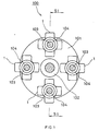
- FIG. 1 is a sectional front view of a cutting device according to a first embodiment of the present invention (a sectional view taken along line S2 ⁇ S2 in FIG. 2).
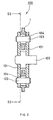
- FIG. 2 is a sectional side view, which is taken along line S1 ⁇ S1 in the cutting device shown in FIG. 1.
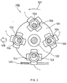
- FIG. 3 is a sectional front view of the cutting device shown in FIG. 1 in a state where the cutting device is cutting a work.
- FIG. 4 is a front view of an impacting body constituting the cutting device shown in FIG. 1.
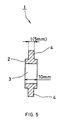
- FIG. 5 is a sectional view taken along line S3 ⁇ S3 in the impacting body shown in FIG. 4.
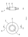
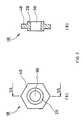
- FIG. 6, FIG. 7, and FIG. 8 show other examples of the impacting body constituting a cutting device.
- a cutting device 100 has the following configuration.
- Spindles 103 are provided between a pair of discs (rotors) 101, 101 whose principal planes oppose each other.
- Impacting bodies 1 are mounted rotatably to the spindles 103, respectively.
- the pair of discs 101, 101 is rotated about a main shaft 102 at a high speed to allow the impacting bodies 1 (hard solid bodies) to impact on a work 105 at least at the critical impact velocity of the work 105.
- a variation of about ⁇ 10% is allowable due to the variation in power supply voltage or other reasons.
- the impact velocity of the impacting bodies 1 against the work 105 naturally corresponds to the rotational speed of the pair of discs 101.
- the present embodiment employs a rotational speed in a high rotational speed range of 10,000 to 60,000 rpm as the rotational speed of the pair of discs 101.
- the high rotational speed range enables, for example, the impact force of the impacting bodies 1 to be increased and the life span to be lengthened by an air-cooling effect and work hardening.
- each impacting body 1 with a planar shape of cruciform each of which has four rectangular projections 4 on the peripheral surface of a cylindrical body 2 provided with a through hole 3 are spaced equally between the principal planes of the discs 101.
- the rectangular projections 4 correspond to cutting blades in a conventional tool and impact on the work 105.
- each impacting body 1 is positioned so that a part (each rectangular projection, i.e. each cutting blade 4) of its periphery is positioned beyond the periphery of the discs 101.
- a predetermined fitting gap 104 is provided between each spindle 103 and the through hole 3 of each impacting body 1 (the fitting gap is set to be about 7 mm in a specific example described later).
- the outer shape of the impacting bodies 1 may be designed freely.
- the outer shape may be a polygon with a plurality of corners (for example, a regular triangle, a regular square, a rectangle, a regular pentagon, or a regular hexagon), a disc shape, an approximate bow shape, or the like.
- FIG. 6, FIG. 7, and FIG. 8 show examples of impacting bodies with a disk shape, a regular hexagonal shape, and an approximate bow shape sequentially.
- FIG. 6 shows a disc impacting body 1A
- FIG. 6A is its front view
- FIG. 6B is its sectional view.
- the disc impacting body 1A has a shape such as one obtained by inserting a cylindrical body 2A with a through hole 3A into the center portion of a ring cutting blade 4A with a predetermined thickness.
- FIG. 7 shows a regular-hexagonal impacting body 1B
- FIG. 7A is its front view
- FIG. 7B is its sectional view.
- the regular-hexagonal impacting body 1B has a shape such as one obtained by inserting a cylindrical body 2B with a through hole 3B into the center portion of a cutting blade 4B having a regular-hexagonal outer shape and a predetermined thickness.
- FIG. 8 shows an impacting body 1C with an approximate bow shape (a "bow and arrow" type bow shape), and FIG. 8A is its front view and FIG. 8B is its side view.
- the impacting body 1C with an approximate bow shape shown in FIG. 8 has a floating portion 5C with an approximate bow shape that is formed of an approximate circular-arc portion and a chord extending between the approximate ends of the circular-arc.
- a cylindrical body 2C having a through hole 3C in its center is formed integrally on one end of the floating portion 5C.
- a cutting blade 4C is formed at the other end of the floating portion 5C.
- the impacting body 1C is mounted to a spindle 103 on rotors with the cutting blade 4C facing forward in the rotational direction.
- the through hole 3C of the impacting body 1C has an elliptical planar shape and is different from the respective though holes 3, 3A, and 3B, each of which has a circular planar shape, in the impacting body 1 shown in FIGS. 4 and 5, the impacting body 1A shown in FIG. 6, and the impacting body 1B shown in FIG. 7, which have rotationally symmetrical shapes.
- the planar shape of the through hole 3C is a circular-arc elliptical shape that is formed by two circular arcs with different radiuses whose centers are the center of gravity of the impacting body 1C and semicircles at their both ends in the circumferential direction.
- the through hole 3C By forming the through hole 3C to be a circular-arc elliptical hole with the two circular arcs whose centers are the center of gravity of the impacting body 1C, the displacement of the impacting body 1C when the impacting body 1C rebounds after impacting on a work can be absorbed excellently, thus improving the cutting performance.
- the rotors 101 may have an arbitrary shape such as a regular polygon. However, it naturally is necessary that the rotors be balanced during rotation.
- each disc 101 had a diameter of 100 mm and a plate thickness of 5 mm.
- the material used for the discs 101 was carbon steel for machine structural use.
- Each spindle 103 had a diameter of 10 mm and its material was carbon steel for machine structural use or carbon tool steel (JIS code: SK2).
- JIS code: SK2 carbon tool steel
- the distance L between top parts of two cutting blades 4 was about 40 mm
- a through hole 3 had a diameter of 17 mm
- each cutting blade 4 had a width w of about 15 mm and a thickness t of about 5 mm.
- the material used for the impacting body 1 was any one selected from carbon steel for machine structural use (S45C), carbon tool steel (SK2), high speed tool steel (SKH2), Ni-Cr steel (SNC631), Ni-Cr-Mo steel (SNCM420), Cr-Mo steel (SCM430), chromium steel (SCr430), manganese steel for machine structural use (SMn433), and the like.
- the disc 101 was rotated at 30,000 rpm in the direction indicated by an arrow 107.
- the impact velocity of the impacting bodies 1 against the work (cold rolled steel plate sheet and strip cut to length with a thickness of 0.8 mm) 105 was set to be about 157 m/second (565 km/hour) and the moving speed for cutting to be 50 mm/second.
- the cutting direction was the direction indicated by an arrow 108.
- the centrifugal force causes a high-speed compressive force accompanied with impacts in a limited area in the work 105 including the surface of the work 105 subjected to the impact (hereinafter referred to as an "impact surface") by the cutting blades 4 of the impacting bodies 1 and the vicinity of the impact surface.
- an impact surface the surface of the work 105 subjected to the impact
- the top layer of the impact surface of the work 105 is smashed at a high speed instantaneously. Cut scraps are in a minute granular state. It has been confirmed by a test that the work 105 can be cut even when no sharp cutting blade is provided.
- a glass included in a CRT also was cut and processed under the above-mentioned processing conditions. It also was confirmed by a test that plastic contained in a resin circuit board for circuit use, a resin-molded article, or the like was processed under the following conditions: the rotational speed of the discs 101 was 10,000 rpm, the number of impacts by the impacting bodies 1 was 40,000 times/minute (four impacting bodies were mounted between the rotors), and the moving speed for cutting was 50 mm/second.
- the impact velocity of the impacting bodies 1 is not limited to the above-mentioned specific example and can be set freely depending on the kind of a work, cutting conditions, or the like as long as the impact velocity is at least the critical impact velocity of the work.
- the number of impacts by the impacting bodies 1 per unit time also can be changed depending on the kind of a work, cutting conditions, or the like.
- members other than metallic members also can be used freely as long as they are hard solid bodies.
- the number of impacting bodies used may be only one or at least two. In the case of providing a plurality of impacting bodies, it is preferred to provide them at equal angles with respect to the rotational center of the rotors, since this results in equal impact intervals to enable stable cutting. In the case of using only one impacting body, a balancer (a weight) is provided to secure the rotational balance.
- the rotor may be driven to be rotated at a high speed using a general spindle motor or the like.
- the impacting bodies 1 of the present invention are not provided with sharp cutting blades as in a conventional cutting tool.
- the cutting principle of the present invention goes beyond a conventional practical sense and enables even brittle members such as metal, resin, glass, ceramics, or the like to be cut without using sharp cutting blades by providing the impacting bodies 1 with a far higher speed than that in a conventional cutting tool.
- FIG. 9 shows a sectional view of a cutting device 600 according to a second embodiment of the present invention.
- the cutting device 600 is assembled by mounting a number of units to one axis. Therefore, the cutting mechanism, cutting and processing conditions, and the like are set to be the same as in the first embodiment.
- numeral 600 indicates a cutting device, numeral 601 discs (rotors), numeral 602 a main shaft, numeral 603 spindles, numeral 604 fitting gaps, numerals 605 and 606 spacers, and numeral 610 a cutting unit.
- the cutting device 600 shown in FIG. 9 is characterized as follows.
- a plurality of cutting units 610 are prepared, each of which is assembled by providing the spindles 603 between a pair of rotors 601, 601 whose principal surfaces oppose each other via the spacer 605 and mounting impacting bodies 1 to the spindles 603 rotatably.
- the cutting units 610 are mounted to the same main shaft 602 at predetermined intervals via the spacers 606.
- the main shaft 602 is rotated at a high speed to allow the impacting bodies 1 to impact on an object to be processed (a work) at least at the critical impact velocity of the work.
- the number and the arrangement pitch of the cutting units 610 to be arranged, the number of the impacting bodies 1 to be mounted between the rotors 601, the impact velocity of the impacting bodies 1, or the like may be set freely depending on the work.
- a cantilever bearing structure With respect to the support for the main shaft 602, a cantilever bearing structure, a double-end support bearing structure, or the like may be employed freely.
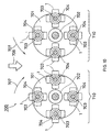
- FIG. 10 shows a sectional front view of a cutting device 700 according to a third embodiment of the present invention.
- the cutting device 700 is obtained by positioning cutting devices according to the first embodiment at a predetermined interval so that their rotational main shafts are arranged in parallel. Therefore, the cutting mechanism, the cutting and processing conditions, and the like are the same as in the first embodiment.
- FIG. 10 shows an example of such a cutting device and is characterized as follows.
- a plurality of cutting units 710 are prepared, each of which is assembled by providing spindles 703 between a pair of rotors 701 whose principal surfaces oppose each other and mounting impacting bodies 1 to the spindles 703 rotatably.
- the cutting units 710 are mounted to two main shafts 702 arranged in parallel.
- the two main shafts 702 are rotated at a high speed in the different directions as indicated by arrows 707 so as to entangle an object to be processed (a work), thus allowing the respective impacting bodies 1 to impact on the work at least at the critical impact velocity of the work.
- numeral 704 indicates a fitting gap between a though hole of an impacting body 1 and a spindle 703
- numeral 708 denotes the direction in which the work is fed.
- the number and the arrangement pitch of the cutting units 710 to be arranged, the number of the impacting bodies 1 to be mounted between the rotors 701, the impact velocity of the impacting bodies 1, or the like may be set freely depending on the work.
- a cantilever bearing structure, a double-end support bearing structure, or the like may be employed freely.
- a number of cutting units 710 may be mounted to one main shaft and may be spaced at predetermined intervals (not shown in the figure).
- a plurality of cutting units are prepared, each of which is assembled by providing spindles between a pair of rotors whose principal surfaces oppose each other and mounting impacting bodies 1 to the spindles rotatably.
- the plurality of cutting units are mounted at predetermined intervals to two main shafts arranged in parallel so that each of the two main shafts is provided with a plurality of cutting units.
- the two main shafts are rotated at a high speed in different directions so as to entangle an object to be processed (a work), thus allowing each impacting body to impact on the work at least at the critical impact velocity of the work.
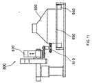
- FIG. 11 shows the side view of cutting and processing equipment according to a fourth embodiment of the present invention.
- the cutting and processing equipment has the configuration in which the cutting device of the first embodiment is mounted to the arm of a robot controlled with five axes (X axis, Y axis, Z axis, angle ⁇ 1, and angle ⁇ 2) (not shown in the figure).
- numeral 800 indicates the cutting and processing equipment
- numeral 810 the cutting device described in the first embodiment
- numeral 820 a commercially available robot controlled with five axes
- numeral 830 an object to be processed (a work, for example, a resin-molded cabinet of electronic equipment or the like)
- numeral 840 a roller conveyor for carrying a carrier pallet
- numeral 850 a carrier pallet on which the work is loaded.
- the cutting device 810 mounted to the arm of the robot 820 is rotated and driven.
- the periphery of the cabinet 830 is cut and processed in a predetermined manner by the five-axes control function (not shown in the figure).
- the impact velocity of the impacting bodies is set to be at least the critical impact velocity of the work 830.
- the above-mentioned equipment may be provided with a following control system (not shown in the figure).
- the control system detects at least one of an intrinsic oscillatory wave form and an intrinsic oscillation frequency that are caused by the impact of the impacting bodies against the work 830 and controls at least one of the impact velocity and impact direction of the impacting bodies and the moving speed of the cutting device 810.
- the work 830 is formed of a plurality of members with different physical properties, even when the material of the work 830 is unknown, or even when the internal structure of the work 830 that cannot be seen from the outside is unknown, optimum cutting conditions can be set automatically, thus achieving the automation of the cutting work.
- the conveyor system may be a belt conveyor or a chain conveyor.
- the cutting device of the second embodiment may be driven by a robot.
Landscapes
- Engineering & Computer Science (AREA)
- Chemical & Material Sciences (AREA)
- Mechanical Engineering (AREA)
- Food Science & Technology (AREA)
- Materials Engineering (AREA)
- Organic Chemistry (AREA)
- Mining & Mineral Resources (AREA)
- Life Sciences & Earth Sciences (AREA)
- Forests & Forestry (AREA)
- Crushing And Pulverization Processes (AREA)
- Processing Of Stones Or Stones Resemblance Materials (AREA)
Abstract
Description
Claims (16)
- A cutting device, comprising:a rotor with a principal plane;a spindle provided on the principal plane; andat least one impacting body mounted on the spindle rotatably,
wherein the impacting body is mounted so that a predetermined fitting gap is provided between the impacting body and the spindle and a part of periphery of the impacting body can be positioned beyond a periphery of the rotor, andthe rotor is rotated at a high speed to allow the impacting body to impact on an object to be processed at least at a critical impact velocity. - A cutting device, comprising:a pair of rotors positioned so that their principal planes oppose each other;a spindle provided between the pair of rotors; andat least one impacting body mounted on the spindle rotatably,
wherein the impacting body is mounted so that a predetermined fitting gap is provided between the impacting body and the spindle and a part of periphery of the impacting body can be positioned beyond peripheries of the rotors, andthe rotors are rotated at a high speed to allow the impacting body to impact on an object to be processed at least at a critical impact velocity. - A cutting device, comprising:a plurality of cutting units, each of which comprises a pair of rotors positioned so that their principal planes oppose each other, a spindle provided between the pair of rotors, and at least one impacting body mounted to the spindle rotatably; anda main shaft to which the plurality of cutting units are mounted at predetermined intervals,
wherein the impacting body is mounted so that a predetermined fitting gap is provided between the impacting body and the spindle and a part of periphery of the impacting body can be positioned beyond peripheries of the rotors, andthe main shaft is rotated at a high speed to allow each impacting body to impact on an object to be processed at least at a critical impact velocity. - A cutting device, comprising:a plurality of cutting units, each of which comprises a pair of rotors positioned so that their principal planes oppose each other, a spindle provided between the pair of rotors, and at least one impacting body mounted to the spindle rotatably; andtwo axes arranged in parallel to which the plurality of cutting units are mounted,
wherein the impacting body is mounted so that a predetermined fitting gap is provided between the impacting body and the spindle and a part of periphery of the impacting body can be positioned beyond peripheries of the rotors, andthe two axes are rotated at a high speed in different directions to allow each impacting body to impact on an object to be processed at least at a critical impact velocity. - A cutting device, comprising:a plurality of cutting units, each of which comprises a pair of rotors positioned so that their principal planes oppose each other, a spindle provided between the pair of rotors, and at least one impacting body mounted to the spindle rotatably; andtwo axes arranged in parallel to which the plurality of cutting units are mounted at predetermined intervals with each of the two axes being provided with a plurality of cutting units,
wherein the impacting body is mounted so that a predetermined fitting gap is provided between the impacting body and the spindle and a part of periphery of the impacting body can be positioned beyond peripheries of the rotors, andthe two axes are rotated at a high speed in different directions to allow each impacting body to impact on an object to be processed at least at a critical impact velocity. - The cutting device according to any of claims 1 to 5, wherein a plurality of the impacting bodies are spaced at equal angles with respect to a rotational center of the rotor.
- The cutting device according to any of claims 1 to 5, wherein the fitting gap between the spindle and the impacting body is at least 2 mm.
- The cutting device according to any of claims 1 to 5, wherein the fitting gap between the spindle and the impacting body is about 5 to 10 mm.
- The cutting device according to any of claims 1 to 5, wherein an outer shape of the impacting body is any one of a polygon with a plurality of corners, a cruciform with a plurality of corners, a disc shape, and an approximate bow shape.
- The cutting device according to any of claims 1 to 5, wherein the impacting body is allowed to impact on the object to be processed at a speed of at least about 139 m/second.
- The cutting device according to any of claims 1 to 5, wherein the impacting body is allowed to impact on the object to be processed at a speed of at least about 340 m/second.
- The cutting device according to any of claims 1 to 5, wherein the impacting body is allowed to impact on the object to be processed at a speed at least twice as high as the critical impact velocity of the object to be processed.
- The cutting device according to any of claims 1 to 5, wherein the cutting device cuts the object to be processed by allowing the impacting body to impact on a surface of the object to be processed to smash the surface.
- Processing equipment, wherein the cutting device according to any of claims 1 to 3 is mounted to an arm of a robot with a multiaxis control function.
- The processing equipment according to claim 14, comprising a control system that detects at least one of an intrinsic oscillatory wave form and an intrinsic oscillation frequency that are generated by an impact of the impacting body on the object to be processed and controls at least one of an impact velocity and impact direction of the impacting body and a moving speed of the cutting device.
- A cutting method of cutting an object to be processed using the cutting device according to any of claims 1 to 5 by allowing the impacting body to impact on the object to be processed at least at the critical impact velocity of the object to be processed.
Applications Claiming Priority (2)
| Application Number | Priority Date | Filing Date | Title |
|---|---|---|---|
| JP1280599 | 1999-01-21 | ||
| JP1280599 | 1999-01-21 |
Publications (2)
| Publication Number | Publication Date |
|---|---|
| EP1022081A2 true EP1022081A2 (en) | 2000-07-26 |
| EP1022081A3 EP1022081A3 (en) | 2003-04-23 |
Family
ID=11815619
Family Applications (1)
| Application Number | Title | Priority Date | Filing Date |
|---|---|---|---|
| EP20000100266 Withdrawn EP1022081A3 (en) | 1999-01-21 | 2000-01-19 | Cutting device, processing equipment, and cutting method |
Country Status (6)
| Country | Link |
|---|---|
| US (2) | US6598813B1 (en) |
| EP (1) | EP1022081A3 (en) |
| JP (1) | JP3523552B2 (en) |
| KR (1) | KR100403408B1 (en) |
| CN (1) | CN1213831C (en) |
| TW (1) | TW430574B (en) |
Cited By (3)
| Publication number | Priority date | Publication date | Assignee | Title |
|---|---|---|---|---|
| EP1300226A1 (en) * | 2001-10-03 | 2003-04-09 | Air-tec AG | Milling cutter wheel for floor milling machines |
| EP1316759A4 (en) * | 2000-08-30 | 2009-04-15 | Panasonic Corp | METHOD FOR DISMANTLING AN AIR CONDITIONER |
| CN115401727A (en) * | 2022-10-06 | 2022-11-29 | 海口坚嫒五金有限责任公司 | Rubber production and processing technology |
Families Citing this family (18)
| Publication number | Priority date | Publication date | Assignee | Title |
|---|---|---|---|---|
| JP2001347416A (en) * | 2000-06-06 | 2001-12-18 | Matsushita Electric Ind Co Ltd | Cutting device and cutting method |
| JP2002031458A (en) * | 2000-07-14 | 2002-01-31 | Matsushita Electric Ind Co Ltd | Refrigerator dismantling method, compression device, and refrigerator dismantling device |
| JP2002144344A (en) * | 2000-11-16 | 2002-05-21 | Matsushita Electric Ind Co Ltd | Method for recovering foamed resin and foaming gas, and method for dismantling refrigerator |
| JP3936268B2 (en) | 2002-09-19 | 2007-06-27 | 株式会社松井製作所 | Shredder |
| FR2863464B1 (en) * | 2003-12-11 | 2006-08-11 | Christian Louis Couronne | SCULTURE FURNITURE METAL / GLASS |
| GB2426757B (en) * | 2005-06-03 | 2008-02-27 | Crt Heaven Ltd | Apparatus and method for cutting a cathode ray tube |
| US20070182238A1 (en) * | 2006-01-17 | 2007-08-09 | Manning Mark C | Cutter for a pavement router |
| US8091455B2 (en) | 2008-01-30 | 2012-01-10 | Cummins Filtration Ip, Inc. | Apparatus, system, and method for cutting tubes |
| RU2446014C2 (en) * | 2010-05-28 | 2012-03-27 | ООО "Кода Инфо" | Universal mill |
| JP2014073463A (en) * | 2012-10-04 | 2014-04-24 | Miken:Kk | Hammer crusher |
| JP6601044B2 (en) * | 2015-07-31 | 2019-11-06 | セイコーエプソン株式会社 | Cutting detection device, printing device, and cutting detection method |
| CN105583031A (en) * | 2015-10-08 | 2016-05-18 | 镇江裕久智能装备股份有限公司 | Crusher used for aluminum scrap recycling |
| CN108160678A (en) * | 2017-12-31 | 2018-06-15 | 天津市元九科技有限责任公司 | Tubular glass instrument batch-processed devices |
| CN113079641B (en) * | 2021-02-23 | 2022-08-19 | 深圳帝显高端制造方案解决有限公司 | Production system and working method of PCB substrate of annular lamp |
| CN113415985B (en) * | 2021-07-26 | 2023-01-06 | 深圳核力新能源科技有限公司 | A cutting device that is used for solar energy industry to be used for solar panel glass |
| CN113578461A (en) * | 2021-09-01 | 2021-11-02 | 宁波回珑再生资源科技股份有限公司 | Hammer type metal crusher |
| CN114195374B (en) * | 2021-11-16 | 2024-04-23 | 兆虹精密(北京)科技有限公司 | Cutting device for ultrathin glass |
| CN114434662B (en) * | 2021-12-22 | 2025-03-04 | 中铁四局集团有限公司 | Centrifugal swing arm railway box girder anchor hole chiseling machine |
Family Cites Families (17)
| Publication number | Priority date | Publication date | Assignee | Title |
|---|---|---|---|---|
| US1557444A (en) * | 1925-07-06 | 1925-10-13 | American Pulverizer | Pulverizing machine |
| US1893030A (en) * | 1929-10-31 | 1933-01-03 | Charles B Kingsley | Crusher for glass and the like |
| US1821482A (en) * | 1930-06-18 | 1931-09-01 | Charles F Schutte | Hammer mill |
| US2045690A (en) * | 1932-03-15 | 1936-06-30 | Jeffrey Mfg Co | Reducing machine |
| US2244577A (en) * | 1939-10-20 | 1941-06-03 | Allen B Schreiber | Mill hammer |
| GB1306673A (en) | 1969-02-27 | 1973-02-14 | Errut Prod Ltd | Machine for treating surfaces |
| US4725097A (en) | 1985-03-06 | 1988-02-16 | Bartell Industries Limited | Inclined cutter for surface cleaning head |
| US5678773A (en) * | 1991-12-02 | 1997-10-21 | Hitachi, Ltd. | Waste processing method and apparatus therefor |
| JPH05337391A (en) | 1992-06-10 | 1993-12-21 | Kubota Corp | Garbage treatment device |
| JP2692509B2 (en) | 1992-08-25 | 1997-12-17 | 株式会社栗本鐵工所 | Impact crusher |
| JPH0721739A (en) | 1993-07-01 | 1995-01-24 | Matsushita Electric Ind Co Ltd | Disc recording / reproducing device |
| US5443216A (en) * | 1994-09-12 | 1995-08-22 | Lajoie; Donald L. | Hammer mill |
| US5562257A (en) * | 1996-01-26 | 1996-10-08 | Magnatech Engineering Incorporated | Double rotor hammermill |
| JP3530305B2 (en) | 1996-04-17 | 2004-05-24 | 新明和工業株式会社 | Machine plate crusher for game machine |
| DE19754371C1 (en) * | 1996-08-27 | 1998-11-26 | Nikolaus Wendel | Milling machine for masonry |
| US6203113B1 (en) | 1997-12-09 | 2001-03-20 | Nick Wendel | Cutting drum with percussive bits |
| JP3994567B2 (en) | 1999-02-05 | 2007-10-24 | 松下電器産業株式会社 | Method and apparatus for removing components from circuit boards |
-
2000
- 2000-01-17 JP JP2000008089A patent/JP3523552B2/en not_active Expired - Fee Related
- 2000-01-18 TW TW089100681A patent/TW430574B/en not_active IP Right Cessation
- 2000-01-18 US US09/484,664 patent/US6598813B1/en not_active Expired - Fee Related
- 2000-01-19 EP EP20000100266 patent/EP1022081A3/en not_active Withdrawn
- 2000-01-21 KR KR10-2000-0002877A patent/KR100403408B1/en not_active Expired - Fee Related
- 2000-01-21 CN CNB00101661XA patent/CN1213831C/en not_active Expired - Fee Related
-
2003
- 2003-04-07 US US10/409,432 patent/US20030167890A1/en not_active Abandoned
Cited By (3)
| Publication number | Priority date | Publication date | Assignee | Title |
|---|---|---|---|---|
| EP1316759A4 (en) * | 2000-08-30 | 2009-04-15 | Panasonic Corp | METHOD FOR DISMANTLING AN AIR CONDITIONER |
| EP1300226A1 (en) * | 2001-10-03 | 2003-04-09 | Air-tec AG | Milling cutter wheel for floor milling machines |
| CN115401727A (en) * | 2022-10-06 | 2022-11-29 | 海口坚嫒五金有限责任公司 | Rubber production and processing technology |
Also Published As
| Publication number | Publication date |
|---|---|
| KR20000053574A (en) | 2000-08-25 |
| JP2000271926A (en) | 2000-10-03 |
| JP3523552B2 (en) | 2004-04-26 |
| US6598813B1 (en) | 2003-07-29 |
| US20030167890A1 (en) | 2003-09-11 |
| TW430574B (en) | 2001-04-21 |
| CN1213831C (en) | 2005-08-10 |
| CN1261566A (en) | 2000-08-02 |
| KR100403408B1 (en) | 2003-10-30 |
| EP1022081A3 (en) | 2003-04-23 |
Similar Documents
| Publication | Publication Date | Title |
|---|---|---|
| US6598813B1 (en) | Cutting device, processing equipment, and cutting method | |
| US6938318B2 (en) | Method for collecting a foam resin from a housing of a refrigerator | |
| US6836947B2 (en) | Method of dismantling air conditioner | |
| US6944926B2 (en) | Method for disassembling refrigerator, compressing device, and device for disassembling the same | |
| US20030131707A1 (en) | Cutting device and cutting method | |
| JP4310840B2 (en) | Crushing device and crushing method | |
| CN110103362B (en) | Movable cutter assembly and crushing device | |
| US20070266833A1 (en) | Method and Mechanism for Increasing Critical Speed in Rotating Disks and Reducing Kerf at High Speeds in Saw Blades | |
| JP2004098222A (en) | Cutting device, processing device, and cutting method | |
| JP4415423B2 (en) | Electronic device dismantling device and dismantling device | |
| EP1405702A1 (en) | Cutting device and cutting method | |
| AU778480B2 (en) | Roll-type crusher | |
| JP3994567B2 (en) | Method and apparatus for removing components from circuit boards | |
| CN210308594U (en) | Move sword subassembly and breaker | |
| Ojolo et al. | Development of a high speed abrasive cutting machine | |
| JPH10373A (en) | Crushing rotary blade | |
| JPS6365963A (en) | Cutting treater | |
| CN105233929A (en) | Special shredder for destroying waste invoices | |
| Lopatukhin et al. | Analysis of the diamond sawing process | |
| JP2000157884A (en) | Crusher for plastics | |
| JPH0672252B2 (en) | How to insert a circular saw | |
| JPH0453654B2 (en) |
Legal Events
| Date | Code | Title | Description |
|---|---|---|---|
| PUAI | Public reference made under article 153(3) epc to a published international application that has entered the european phase |
Free format text: ORIGINAL CODE: 0009012 |
|
| AK | Designated contracting states |
Kind code of ref document: A2 Designated state(s): DE FR GB |
|
| AX | Request for extension of the european patent |
Free format text: AL;LT;LV;MK;RO;SI |
|
| PUAL | Search report despatched |
Free format text: ORIGINAL CODE: 0009013 |
|
| AK | Designated contracting states |
Designated state(s): DE FR GB |
|
| AX | Request for extension of the european patent |
Extension state: AL LT LV MK RO SI |
|
| RIC1 | Information provided on ipc code assigned before grant |
Ipc: 7B 28D 1/18 B Ipc: 7B 26D 7/08 B Ipc: 7B 23D 57/00 A |
|
| 17P | Request for examination filed |
Effective date: 20030813 |
|
| AKX | Designation fees paid |
Designated state(s): DE FR GB |
|
| 17Q | First examination report despatched |
Effective date: 20031203 |
|
| STAA | Information on the status of an ep patent application or granted ep patent |
Free format text: STATUS: THE APPLICATION IS DEEMED TO BE WITHDRAWN |
|
| 18D | Application deemed to be withdrawn |
Effective date: 20050405 |