EP1021269B1 - Arrangement with transfer of measured values - Google Patents
Arrangement with transfer of measured values Download PDFInfo
- Publication number
- EP1021269B1 EP1021269B1 EP98943165A EP98943165A EP1021269B1 EP 1021269 B1 EP1021269 B1 EP 1021269B1 EP 98943165 A EP98943165 A EP 98943165A EP 98943165 A EP98943165 A EP 98943165A EP 1021269 B1 EP1021269 B1 EP 1021269B1
- Authority
- EP
- European Patent Office
- Prior art keywords
- voltage
- measurement
- winding
- welding
- power
- Prior art date
- Legal status (The legal status is an assumption and is not a legal conclusion. Google has not performed a legal analysis and makes no representation as to the accuracy of the status listed.)
- Expired - Lifetime
Links
Images
Classifications
-
- B—PERFORMING OPERATIONS; TRANSPORTING
- B23—MACHINE TOOLS; METAL-WORKING NOT OTHERWISE PROVIDED FOR
- B23K—SOLDERING OR UNSOLDERING; WELDING; CLADDING OR PLATING BY SOLDERING OR WELDING; CUTTING BY APPLYING HEAT LOCALLY, e.g. FLAME CUTTING; WORKING BY LASER BEAM
- B23K9/00—Arc welding or cutting
- B23K9/06—Arrangements or circuits for starting the arc, e.g. by generating ignition voltage, or for stabilising the arc
- B23K9/067—Starting the arc
- B23K9/0672—Starting the arc without direct contact between electrodes
- B23K9/0673—Ionisation of the arc gap by means of pulsed or high-frequency voltages
Definitions
- the present invention relates to an arrangement for material transport and/or energy transport by means of electric arc. Measured values are transferred with suppression of disturbances from the HF device without appreciable damping of the HF voltage to the electrode.
- the fed-back measured value is often used to regulate the welding process in order to obtain an even droplet transfer with minimum weld splatter.
- the aim of the feed-back is in most cases to prevent dipping of the electrode in the molten pool, which would lead both to a destroyed electrode tip and to inadmissible inclusions of electrode material in the weld deposit.
- a special case is mechanized TIG welding when joining pipes or welding pipes into end plates, where the arc length and thus the height of the welding electrode above the workpiece are regulated as a function of the arc voltage.
- This height control is used, for example, to bridge variable roundness of the pipes or to adapt the height in multiple pass welding, when the weld seam laid during the preceding pass is contacted.
- the aim can also be to register welding data for the purpose of monitoring quality.
- a high-frequency device In order to create reliable arc ignitions when the quality and/or productivity requirements are high, a high-frequency device (HF device) is often used which superposes high-frequency high voltage on the open-circuit voltage fed from the current source to the welding electrode. An HF spark ionizes the protective gas between electrode and workpiece and the arc can be established. The HF device is then switched off normally, and the arc is maintained thereafter with ordinary welding voltage. When welding with alternating current, it may also happen that HF is not only used at the outset, but is also used in order to keep the arc burning at the zero passages of the welding voltage.
- a transformer is often used to connect the HF voltage to the welding cable.
- a characteristic feature is that the secondary winding of the transformer is dimensioned to withstand the total welding current. This transformer transfer can be done for reasons relating to personal safety.
- the HF device in question permits connection without transformer, there is often an inductor with or without core connected between current source and HF device in order to prevent the HF voltage from entering the power part of the current source.
- the voltage drop across the cables is considerable if the voltage measurement takes place at the welding current source connections. For this reason, the measurement advantageously takes place in direct proximity to the electrode, and a separate measurement line leads the voltage value back to the current source. Since the return line from workpiece to current source can often be dimensioned for minimum voltage drop, while the welding cable must be dimensioned smaller on account of requirements relating inter alia to ease of handling for the welder, or automatic welding torch manipulator, the measurement in these cases can take place relative to the return cable socket of the current source, and thus a single measurement line is sufficient.
- a second problem at the high frequency is the difficulty involved in maintaining sufficient impedance with respect to the rest of the equipment so that the HF voltage is not damped en route from HF device to welding electrode.
- a further problem is that the high HF voltage breaks down the insulation upon long-term exposure unless use is made of large insulating distances and high-quality insulation material.
- the above-mentioned filter must be made extremely robust. High-quality components, large insulating distances, requirements in respect of casting in order to avoid corona effects, etc., lead to large physical dimensions and high costs.
- the filter In order to avoid capacitive damping of the HF voltage, the filter has to be placed near the electrode. The dimensions mean that the measurement line often has to be laid physically separate from the welding cable, which further adversely affects the HF voltage, as the damping via the capacitance to earth increases when these are laid on a floor, for example.
- the object of the invention is to make available an arrangement which affords a solution to the above problems without having the disadvantages inherent to the prior art.
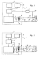
- this object is achieved by the fact that the filter in Fig. 1 is replaced by an extra winding on the existing transformer or inductor and that this winding, hereinafter called the measurement winding, on the control part side is decoupled with a capacitor according to Fig. 2 or Fig. 3.
- the measurement winding consists of a thin cable with good insulation, which is wound together with the winding which carries the welding current.
- the measurement winding must in principle have the same number of turns as this weld winding and must have the same direction of winding.
- the principle is that equally high HF voltage is induced in the measurement winding as in the welding winding.
- the two windings are decoupled as shown in Figs 2 and 3 with capacitors at the end towards the control and/or measurement part or the power part, respectively, of the current source, so that the HF voltage is negligible there. Since the direction of winding is common, the potential difference between measurement line and welding line is low, and the lines can be coupled together at, for example, the same point in the welding head without the HF voltage between electrode and workpiece being damped to any great extent.
- Measurement line and welding cable can advantageously be laid in the same outer sheath, which provides a robust and flexible cabling.
- Typical equipment for mechanized TIG welding for example of pipe joints, will be taken to illustrate the invention.
- Such equipment comprises a current source 1, a welding cable 11, a welding torch 13 with electrode 14, and a return cable 12 from the workpiece 15.
- the current source comprises a power part 6, a control part 5, a manoeuvring unit 4, a motor drive 3 for positioning the welding head, on the one hand, along the seam, and, on the other hand, vertically and sometimes also laterally, an HF device 2, a transformer 88 for galvanic isolation and step-up transformation of the voltage from the HF device, and a capacitor 7 for HF decoupling.
- the HF device 2 is activated for a short time while the power part is emitting open-circuit voltage to the welding torch.
- the protective gas which is being fed through the welding torch has been ionized by HF spark between electrode and workpiece, current begins to flow from the power unit 6 through the power winding 8; 98, welding cable 11, electrode 14, arc, workpiece 15 and return cable 12.
- the voltage across the arc is now of the order of 8 - 15 V.
- arc voltage Since the arc voltage is dependent on the arc length, this is used as a control parameter when the control part 5 is controlling the motor drive 3 for vertical holding of the torch head.
- a typical feature of TIG welding is that the current is pulsed, and thus the voltage drop varies particularly across the welding cable 11. For this reason, among others, it is very important to measure the arc voltage near the electrode 14.
- a separate measurement line 10 is therefore arranged running from torch 13 to control part 5.
- the problem of protecting the control part from the HF voltage has previously been solved using a filter 9. The difficulties in constructing the latter so that it damps the HF voltage sufficiently in relation to the control part without at the same time loading and thus damping the HF voltage at the electrode, and the problems of withstanding the high voltage over the long term, have already been touched upon.
- a far more elegant, more efficient and more economical solution is to introduce a measurement winding 16 which, upon manufacture of the HF transformer 88, is co-wound with the secondary coil 8 of the latter. The same voltage is induced at 16 and 8, and in this way the HF voltage at the electrode is not loaded by the measurement line 10.
- Capacitive loading between measurement cable and earth can now also be avoided by means of the measurement cable being laid in immediate proximity to the welding cable 11, which of course has the same potential as the measurement cable, except for a few volts of voltage drop on account of the welding current. In this way, the extra load which the measurement cable represented for the HF voltage at the welding torch has been largely eliminated.
- Capacitor 17 decouples any residual voltage from the HF voltage at the control part input.
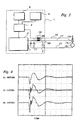
- FIG. 3 A second embodiment is shown in Fig. 3, where the HF device itself generates sufficient voltage and is galvanically isolated from the mains voltage. No transformer is needed here, but an inductor 99 is required for protecting the power part 6. A measurement winding 16 is co-wound in the same way with the inductor winding 98.
- Fig. 4 shows examples of voltage/time diagrams for the HF voltage. showers of the pulses shown occur at a repetition frequency of 50 - 600 Hz as long as the HF device is activated.
- the invention provides an elegant way of connecting a measurement cable and at the same time of protecting the measuring equipment from damaging high voltage, without adversely affecting the spark.
Landscapes
- Engineering & Computer Science (AREA)
- Physics & Mathematics (AREA)
- Plasma & Fusion (AREA)
- Mechanical Engineering (AREA)
- Arc Welding Control (AREA)
- Arc Welding In General (AREA)
- Investigating Or Analysing Materials By The Use Of Chemical Reactions (AREA)
- Investigating Or Analysing Materials By Optical Means (AREA)
- Spectrometry And Color Measurement (AREA)
Abstract
Description
Claims (9)
- Apparatus for material transfer and/or energy transfer by means of electric arc between tool (13) and receiver (15), comprising a power part (6), a control and/or measurement part (5), an HF device (2) which generates high-frequency high voltage, a first component (7) with low impedance with respect to high-frequency high voltage, a process cable (11) for energy transport to the tool, an inductive element arranged between the process cable and the power part with power winding (8; 98), a measurement line (10) and, arranged between the latter and the control and/or measurement part, a disturbance-suppressing element (16), characterized in that the disturbance-suppressing element comprises a measurement winding (16), arranged so that the voltage induced therein and in the power winding (8; 98) has the same polarity in relation to the tool.
- Apparatus according to Claim 1, characterized in that the disturbance-suppressing element also comprises a second component (17) with low impedance with respect to high-frequency high voltage, which component damps any residual voltage from the HF voltage, and in that the power winding (8; 98) and the measurement winding (16) have essentially the same number of turns.
- Apparatus according to Claim 1 or 2, characterized in that the measurement line (10) and process cable (11) are laid in immediate proximity to each other.
- Apparatus according to any of the preceding claims, characterized in that the power winding and measurement winding are co-wound.
- Apparatus according to any of the preceding claims, characterized in that the HF device is coupled-in intermittently and during this transfers to the process cable (11) showers of pulses with voltage between 1 and 30 kV and frequencies of between 0.1 and 10 MHz.
- Apparatus according to any of the preceding claims, characterized in that the signal in the measurement line (10) has a frequency of less than 10 kHz.
- Apparatus according to any of the preceding claims, characterized in that material transported by the arc is metallic.
- Apparatus according to any of the preceding claims, characterized in that the receiver (15) is made of metal.
- Apparatus according to any of the preceding claims, characterized in that the power part (6) constitutes a current source for direct current.
Applications Claiming Priority (3)
| Application Number | Priority Date | Filing Date | Title |
|---|---|---|---|
| SE9703282 | 1997-09-10 | ||
| SE9703282A SE518120C2 (en) | 1997-09-10 | 1997-09-10 | Device with measured value transfer |
| PCT/SE1998/001614 WO1999012691A1 (en) | 1997-09-10 | 1998-09-10 | Arrangement with transfer of measured values |
Publications (2)
| Publication Number | Publication Date |
|---|---|
| EP1021269A1 EP1021269A1 (en) | 2000-07-26 |
| EP1021269B1 true EP1021269B1 (en) | 2003-04-09 |
Family
ID=20408216
Family Applications (1)
| Application Number | Title | Priority Date | Filing Date |
|---|---|---|---|
| EP98943165A Expired - Lifetime EP1021269B1 (en) | 1997-09-10 | 1998-09-10 | Arrangement with transfer of measured values |
Country Status (7)
| Country | Link |
|---|---|
| US (1) | US6316745B1 (en) |
| EP (1) | EP1021269B1 (en) |
| AT (1) | ATE236755T1 (en) |
| DE (1) | DE69813268T2 (en) |
| DK (1) | DK1021269T3 (en) |
| SE (1) | SE518120C2 (en) |
| WO (1) | WO1999012691A1 (en) |
Cited By (2)
| Publication number | Priority date | Publication date | Assignee | Title |
|---|---|---|---|---|
| EP4052830A1 (en) | 2021-03-01 | 2022-09-07 | Fronius International GmbH | Decoupling device for hf voltage on a data line |
| EP4169649A1 (en) | 2021-10-19 | 2023-04-26 | FRONIUS INTERNATIONAL GmbH | Method and device for implementation of a welding process |
Families Citing this family (1)
| Publication number | Priority date | Publication date | Assignee | Title |
|---|---|---|---|---|
| EP3623095A1 (en) * | 2018-09-17 | 2020-03-18 | FRONIUS INTERNATIONAL GmbH | Welding device and method for welding with self-adjusting welding wire feed speed |
Family Cites Families (4)
| Publication number | Priority date | Publication date | Assignee | Title |
|---|---|---|---|---|
| BE500615A (en) * | 1950-01-17 | |||
| US2784349A (en) * | 1951-12-28 | 1957-03-05 | Air Reduction | Electric arc welding |
| GB1425831A (en) * | 1972-01-31 | 1976-02-18 | Austin M A | Electric arc welding |
| US4350868A (en) * | 1975-07-14 | 1982-09-21 | Matsushita Electric Industrial Co., Ltd. | Follow-up control apparatus for controlling the movement of a welding weaving device |
-
1997
- 1997-09-10 SE SE9703282A patent/SE518120C2/en not_active IP Right Cessation
-
1998
- 1998-09-10 AT AT98943165T patent/ATE236755T1/en active
- 1998-09-10 EP EP98943165A patent/EP1021269B1/en not_active Expired - Lifetime
- 1998-09-10 US US09/508,315 patent/US6316745B1/en not_active Expired - Lifetime
- 1998-09-10 DE DE69813268T patent/DE69813268T2/en not_active Expired - Lifetime
- 1998-09-10 WO PCT/SE1998/001614 patent/WO1999012691A1/en not_active Ceased
- 1998-09-10 DK DK98943165T patent/DK1021269T3/en active
Cited By (4)
| Publication number | Priority date | Publication date | Assignee | Title |
|---|---|---|---|---|
| EP4052830A1 (en) | 2021-03-01 | 2022-09-07 | Fronius International GmbH | Decoupling device for hf voltage on a data line |
| WO2022184613A1 (en) | 2021-03-01 | 2022-09-09 | Fronius International Gmbh | Welding assembly comprising a welding device and a welding component connected to the welding device |
| EP4169649A1 (en) | 2021-10-19 | 2023-04-26 | FRONIUS INTERNATIONAL GmbH | Method and device for implementation of a welding process |
| WO2023066857A1 (en) | 2021-10-19 | 2023-04-27 | Fronius International Gmbh | Device and method for carrying out a welding process |
Also Published As
| Publication number | Publication date |
|---|---|
| SE9703282D0 (en) | 1997-09-10 |
| SE9703282L (en) | 1999-03-11 |
| WO1999012691A1 (en) | 1999-03-18 |
| EP1021269A1 (en) | 2000-07-26 |
| SE518120C2 (en) | 2002-08-27 |
| DE69813268D1 (en) | 2003-05-15 |
| ATE236755T1 (en) | 2003-04-15 |
| DE69813268T2 (en) | 2004-01-29 |
| DK1021269T3 (en) | 2003-07-28 |
| US6316745B1 (en) | 2001-11-13 |
Similar Documents
| Publication | Publication Date | Title |
|---|---|---|
| US5455573A (en) | Inductive coupler for well tools | |
| EP1016484A1 (en) | Method and device for welding egnition for arc welding apparatus | |
| US4943699A (en) | System for supplying power | |
| US4918285A (en) | System for supplying power | |
| EP1021269B1 (en) | Arrangement with transfer of measured values | |
| EP0251423A2 (en) | Improvements relating to welding | |
| Makhlin et al. | Analysis and procedure of calculation of series connection electronic devices for contactless arc excitation | |
| EP0862499B1 (en) | System for treating gases or fluids with pulsed corona discharges | |
| KR100264307B1 (en) | A method and apparatus for starting the arc | |
| CA2137594A1 (en) | Welding apparatus for studs of annular cross-section | |
| CA2461810C (en) | Method and apparatus for welding with high frequency protection | |
| US7288741B2 (en) | Arc welder | |
| CN113165097B (en) | Submerged arc welding systems and submerged arc welding torches for resistively preheating the electrode wire | |
| US20070251933A1 (en) | Welding system toroidal spark gap method and system | |
| EP2237917A2 (en) | Electric welding of aluminium or aluminium alloy | |
| KR200170059Y1 (en) | Welding cable assembly | |
| US3117215A (en) | Alternating current contant potential welding apparatus | |
| CN116887939B (en) | Welding assembly having a welding device and a welding component connected to the welding device | |
| US20240316676A1 (en) | Device and method for carrying out a welding process | |
| JPH0750055Y2 (en) | Arc ignition device | |
| KR20060069230A (en) | Welding system using multiple arcs | |
| JPS6225070B2 (en) | ||
| JP2540375Y2 (en) | TIG arc welding machine | |
| JPH04135073A (en) | Tig arc welding machine | |
| KR19980060062U (en) | Welding cable assembly |
Legal Events
| Date | Code | Title | Description |
|---|---|---|---|
| PUAI | Public reference made under article 153(3) epc to a published international application that has entered the european phase |
Free format text: ORIGINAL CODE: 0009012 |
|
| 17P | Request for examination filed |
Effective date: 20000406 |
|
| AK | Designated contracting states |
Kind code of ref document: A1 Designated state(s): AT DE DK FI FR GB IT |
|
| GRAH | Despatch of communication of intention to grant a patent |
Free format text: ORIGINAL CODE: EPIDOS IGRA |
|
| RIN1 | Information on inventor provided before grant (corrected) |
Inventor name: KARLSSON, ROLF |
|
| GRAH | Despatch of communication of intention to grant a patent |
Free format text: ORIGINAL CODE: EPIDOS IGRA |
|
| GRAA | (expected) grant |
Free format text: ORIGINAL CODE: 0009210 |
|
| AK | Designated contracting states |
Designated state(s): AT DE DK FI FR GB IT |
|
| REG | Reference to a national code |
Ref country code: GB Ref legal event code: FG4D |
|
| REG | Reference to a national code |
Ref country code: DK Ref legal event code: T3 |
|
| PGFP | Annual fee paid to national office [announced via postgrant information from national office to epo] |
Ref country code: FI Payment date: 20030930 Year of fee payment: 6 |
|
| ET | Fr: translation filed | ||
| PLBE | No opposition filed within time limit |
Free format text: ORIGINAL CODE: 0009261 |
|
| STAA | Information on the status of an ep patent application or granted ep patent |
Free format text: STATUS: NO OPPOSITION FILED WITHIN TIME LIMIT |
|
| 26N | No opposition filed |
Effective date: 20040112 |
|
| PG25 | Lapsed in a contracting state [announced via postgrant information from national office to epo] |
Ref country code: FI Free format text: LAPSE BECAUSE OF NON-PAYMENT OF DUE FEES Effective date: 20040910 |
|
| PGFP | Annual fee paid to national office [announced via postgrant information from national office to epo] |
Ref country code: DK Payment date: 20100913 Year of fee payment: 13 |
|
| REG | Reference to a national code |
Ref country code: DK Ref legal event code: EBP |
|
| PG25 | Lapsed in a contracting state [announced via postgrant information from national office to epo] |
Ref country code: DK Free format text: LAPSE BECAUSE OF NON-PAYMENT OF DUE FEES Effective date: 20110930 |
|
| REG | Reference to a national code |
Ref country code: FR Ref legal event code: PLFP Year of fee payment: 18 |
|
| REG | Reference to a national code |
Ref country code: FR Ref legal event code: PLFP Year of fee payment: 19 |
|
| REG | Reference to a national code |
Ref country code: FR Ref legal event code: PLFP Year of fee payment: 20 |
|
| PGFP | Annual fee paid to national office [announced via postgrant information from national office to epo] |
Ref country code: IT Payment date: 20170925 Year of fee payment: 20 Ref country code: FR Payment date: 20170925 Year of fee payment: 20 Ref country code: GB Payment date: 20170927 Year of fee payment: 20 |
|
| PGFP | Annual fee paid to national office [announced via postgrant information from national office to epo] |
Ref country code: AT Payment date: 20170821 Year of fee payment: 20 |
|
| PGFP | Annual fee paid to national office [announced via postgrant information from national office to epo] |
Ref country code: DE Payment date: 20170927 Year of fee payment: 20 |
|
| REG | Reference to a national code |
Ref country code: DE Ref legal event code: R071 Ref document number: 69813268 Country of ref document: DE |
|
| REG | Reference to a national code |
Ref country code: GB Ref legal event code: PE20 Expiry date: 20180909 |
|
| REG | Reference to a national code |
Ref country code: AT Ref legal event code: MK07 Ref document number: 236755 Country of ref document: AT Kind code of ref document: T Effective date: 20180910 |
|
| PG25 | Lapsed in a contracting state [announced via postgrant information from national office to epo] |
Ref country code: GB Free format text: LAPSE BECAUSE OF EXPIRATION OF PROTECTION Effective date: 20180909 |
|
| P01 | Opt-out of the competence of the unified patent court (upc) registered |
Effective date: 20230522 |